Northern Lights GEM Series User manual

www.northern-lights.com
Corporate Headquarters
4420 14th Avenue NW
Seattle, WA 98107
Tel: (206) 789-3880
Fax: (206) 782-5455
Southeastern U.S.A.
1419 W Newport Center Dr
Deereld Beach, FL 33442
Tel: (954) 421-1717
Fax: (954) 421-1712
Alaska Branch Ofce
1200 West International
Airport Road
Anchorage, AK 99519
Tel: (907) 562-2222
Fax: (907) 563-1921
East Coast Branch
15 Aegean Dr.
Suite 4
Methuen MA 01844
Tel: (978) 475-7400
Fax: (978) 475-7745
Gulf Branch
19 Veterans Memorial Blvd.
Kenner, LA 70062
Tel: (504) 360-2180
Toll Free: (800) 843-6140
M843W3
GEM Series Sound Enclosure
Assembly Instructions
M843NW3 GEM SOUND ENCLOSURE ASSEMBLY INSTRUCTIONS
COVER IMAGE

L815 - 10/18

Specications:
Enclosure (Installed on Generator Base):
Length (OA)...........................................................38.8 in (986 mm)
Width.....................................................................22.6 in (574 mm)
Height....................................................................25.8 in (655 mm)
Assembled Weight:
43 lbs (19.5 kg) shield only
787 lbs (357 kg) with generator set
1
M843NW3
GEM SERIES SOUND ENCLOSURE
ITEM DESCRIPTION NLI P/N QTY NOTES
1 JUNCTION BLOCK OFF PLATE ASSEMBLY 06-73111 1
2 REAR PANEL ASSEMBLY 06-73102 1 Includes 06-73108
3 M8 FLAT WASHER 15-11000 4 Loose, bagged
4 M8 LOCK WASHER 15-00705 4 Loose, bagged
5 M8 HEX HEAD CAPSCREW 12-00776 4 Loose, bagged
6 1/4” NPT BRASS PIPE NIPPLE 21-00201 2 Loose, bagged
7 1/4” NPT BRASS PIPE CAP 21-72241 2 Loose, bagged
8 SOUND FOAM, SNORKEL RECEIVER SEAL 55-73174 1 Loose, bagged
9 BOTTOM SIDE VALENCE ASSEMBLY 06-73104 2
10 FRONT BOTTOM VALENCE ASSEMBLY 06-73108 1
11 NON-SERVICE SIDE PANEL ASSEMBLY 06-73107 1
12 SERVICE SIDE PANEL AFT ASSEMBLY 06-73106 1
13 FRONT PANEL ASSEMBLY 06-73101 1
14 SEAL BAR ASSEMBLY 06-73110 1
15 TOP PANEL ASSEMBLY 00-73103 1
16 SERVICE SIDE PANEL, FWD ASSEMBLY 00-73105 1
17 GROMMET 1-1/8” ID X 1-7/8” OD 00-70083 2 Loose, bagged

2
Prior to assembly, inspect all components for damage. Report any damage to the shipping
company. Check the packing list in the back of this manual to be sure all parts are included.
Select a mounting location in accordance with the guidelines in the IM1000 Installation Manual.
The generator set must typically be mounted on a rigid, at surface above a strong structure,
such as the vessel’s stringers, to minimize vibration transference to the hull.
Note that the generator set is designed for single side service. When viewed from the rear, the
right hand side is the service side and should be exposed for easy maintenance access.
Install the generator set in the vessel as near to a level attitude as possible. Ensure that the
enclosure’s left hand side and rear are at the recommended distances (6 inch recommended,
4 inch minimum.) from the vessel’s bulkheads.
AVOID POSITIONING THE ENCLOSURE INTO CORNERS WITH OVERHEAD BLOCKED TO
REDUCE CHANCE OF INTAKE/EXHAUST AIR RECIRCULATION OUTSIDE THE SHIELD.
A
Note: The Generator set features a single point lifting eye. However, the generator may still possess
original factory lifting points, which need to be loosened and rotated down, until they are below the
highest point of the engine. Be sure to retighten those bolts before moving on.
PRIOR TO SOUND SHIELD ASSEMBLY, START WITH ITEM #1 SHOWN IN THE
FOLLOWING ILLUSTRATIONS.

3

4
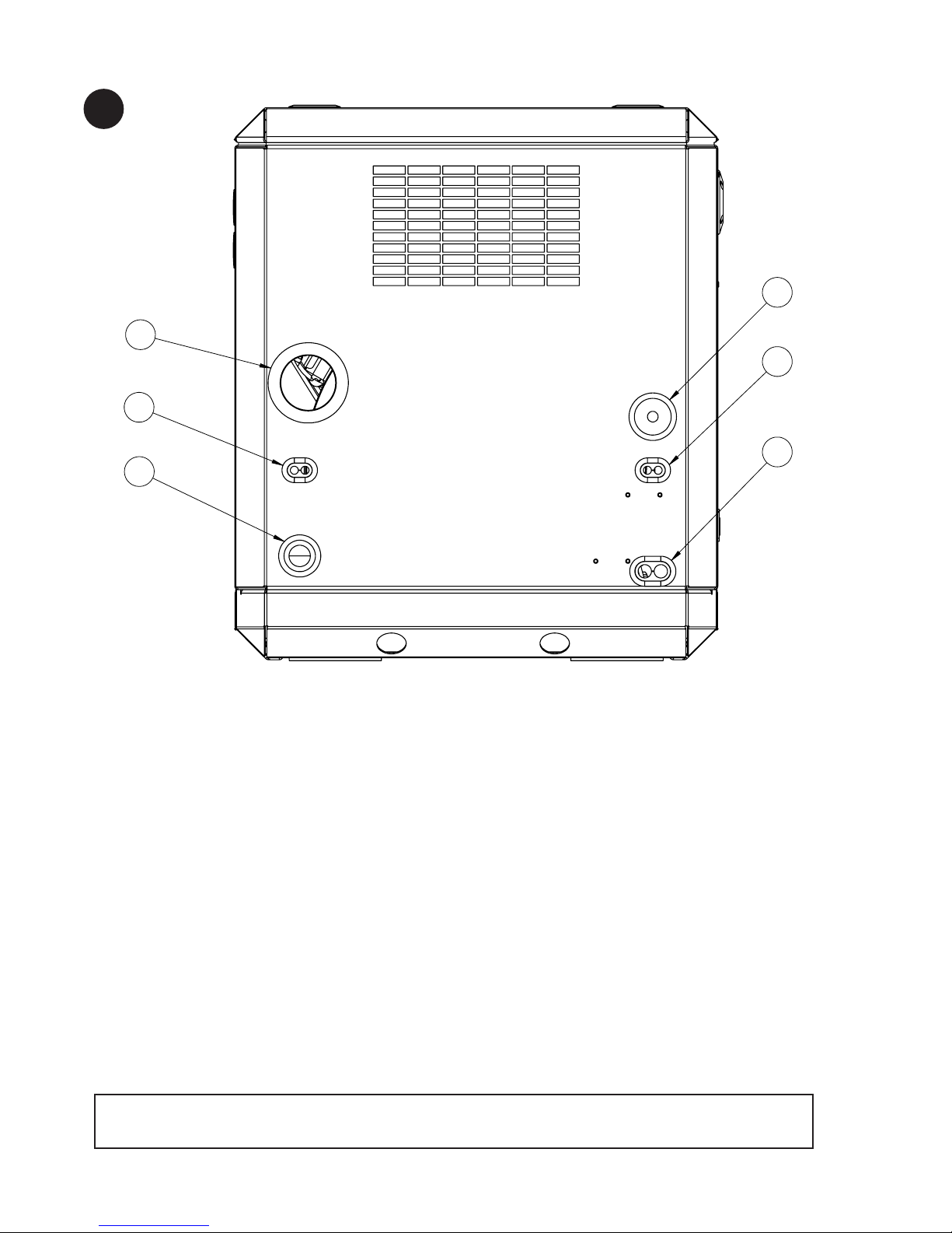
You may encounter some resistance as the
rear panel comes into contact with the air intake
snorkel hose. Note that the rear panel has a
small hole in the vicinity of the intake snorkel.
Guide this hose so that it is inserted in the panel
hole, ensure that the hose does not go too far
into the rear panel, blocking the hose end.
(Generally this hose will install without
adjustment at the retaining clamp.)
Note: The Generator set features a single point lifting eye. However, the generator may still possess
original factory lifting points, which need to be loosened and rotated down, until they are below the
highest point of the engine. Be sure to retighten those bolts before moving on.
B

5
C

6
D

7
E

8
F

9
G

10
H

11
I

12
Install connections for exhaust, AC power leads, DC Control panel leads, battery and water
through holes in the rear panel as shown above and described below:
a. Connect the genset 2” OD exhaust outlet to the exhaust system of the vessel.
b. Connect the sea water pump to the vessel’s water inlet. Push a 3/4” hose from the vessel’s
sea water strainer through the lower hole at the bottom left of the rear panel to the sea water
pump inlet tting.
c. Connect the vessel’s fuel lines using Coast Guard approved rubber fuel hoses to the fuel
manifold inside the sound shield. The outer tting is 5/16” 37T JIC fuel suction, and the tting
is 1/4” 37T JIC fuel return.
d. Connect the DC control harness to the engine harness plug. Pass the harness and plug
through the hole at the mid-section of the right side of the rear panel.
e. Connect the battery leads to the generator set passing the two leads through the second hole
above the bottom left side of the rear panel.
f. Connect the AC output leads from the generator to the vessel’s power distribution panel. Pass
the two leads through the middle hole on the right side of the rear panel.
J
Note: This unit features new, non-displaceable penetration grommeting for the AC, DC, and battery
cables. Therefore, the t will be snug.
A
E
B
D
F
C
J
PAGE 12

13
IF YOU HAVE CHOSEN TO INSTALL A SIPHON BREAK:
Note the pre-installed penetration point in the upper left corner of the non-service side panel.
Reference the plumbing diagram in the mounting and exhaust sections of the IM1000 installation
manual.
Remove the white plastic hole plugs by pushing them out from the inside and replace with the
two rubber grommets (item 17) provided.
a. Disconnect the hose from the seawater pump output and from the rubber elbow on the
expansion tank. Install two lengths of 3/4” hose. The hoses must be of adequate length to
allow mounting of a siphon break, a minimum of 12 inches above the vessel’s loaded water
line.
b. Pass the seawater pump output hose through the top hole in the panel. The hose from the
expansion tank must go through the bottom hole in the panel.
c. For more information, see the “Exhaust” section of IM1000 Installation Manual.
K
CAUTION: GENERATOR SETS WITH WET EXHAUST THAT ARE INSTALLED NEAR OR BELOW
THE VESSEL’S WATER LINE MUST USE A SIPHON BREAK TO PREVENT BACKFLOW OR WATER
INTO THE ENGINE. THIS BACKFLOW CAN RUIN AN ENGINE AND POSSIBLY SINK THE VESSEL.
NON SERVICE SIDE PANEL
OUT FROM VENTED LOOP
IN FROM VENTED LOOP
PAGE 13

M843NW3 SOUND SHIELD PACKING LIST
L815 10/18
ITEM DESCRIPTION NLI P/N QTY PACKED
1 JUNCTION BLOCK OFF PLATE ASSEMBLY 06-78110 1 p
2 REAR PANEL ASSEMBLY, Includes 06-73108 06-73102 1 p
9 BOTTOM SIDE VALENCE ASSEMBLY 06-73104 2 p
10 FRONT BOTTOM VALENCE ASSEMBLY 06-73108 1 p
11 NON-SERVICE SIDE PANEL ASSEMBLY 06-73107 1 p
12 SERVICE SIDE PANEL AFT ASSEMBLY 06-73106 1 p
13 FRONT PANEL ASSEMBLY 06-73101 1 p
14 SEAL BAR ASSEMBLY 06-73110 1 p
15 TOP PANEL ASSEMBLY 00-73103 1 p
16 SERVICE SIDE PANEL, FWD ASSEMBLY 00-78105 1 p
HARDWARE BAG:
3 M8 FLAT WASHER 15-11000 4 Loose p
4 M8 LOCK WASHER 15-00705 4 Loose p
5 M8 HEX HEAD CAPSCREW 12-00776 4 Loose p
6 1/4” NPT BRASS PIPE NIPPLE 21-00201 2 Loose p
7 1/4” NPT BRASS PIPE CAP 21-72241 2 Loose p
8 SOUND FOAM, SNORKEL RECEIVER SEAL 55-78174 1 Loose p
17 GROMMET, 1-1/8” ID x 1-7/8” OD 00-70083 2 Loose p
Packed By: ________________________________ Date: ___________________________
Other manuals for GEM Series
3
This manual suits for next models
1
Table of contents
Other Northern Lights Enclosure manuals
Popular Enclosure manuals by other brands

Blaupunkt
Blaupunkt Blaubox owner's manual

Phanteks
Phanteks Eclipse Series Quick installation guide

Diablotek
Diablotek CPA-808 Specifications

PCB Piezotronics
PCB Piezotronics IMI SENSORS PCB-691A50/04 Installation and operating manual

Supermicro
Supermicro SC846B JBOD user manual

Ubiquiti
Ubiquiti IsoBeam ISO-BEAM-16 quick start guide

DEC
DEC BA400 Series installation manual

Netstor
Netstor TurboBox Xtreme Quick installation guide

SINGULARITY COMPUTERS
SINGULARITY COMPUTERS SPECTRE INTEGRA-M Assembly manual

hager
hager Quadro Plus User instructions

Icy Box
Icy Box IB-373U3 user manual

Dell
Dell PowerVault MD3200 Series Getting started guide