Northern Telecom CONFERENCE 2000 Guide
I
~
nu,thc,n
--"
talacum
PRACTICE 512-6261-200
P0594715
Issued: 83 02 04
Standard
"CONFERENCE 2000" TELECONFERENCE TERMINAL
QTAF-TYPES
DESCRIPTION, INSTALLATION, OPERATION,
MAINTENANCE, AND CONNECTIONS
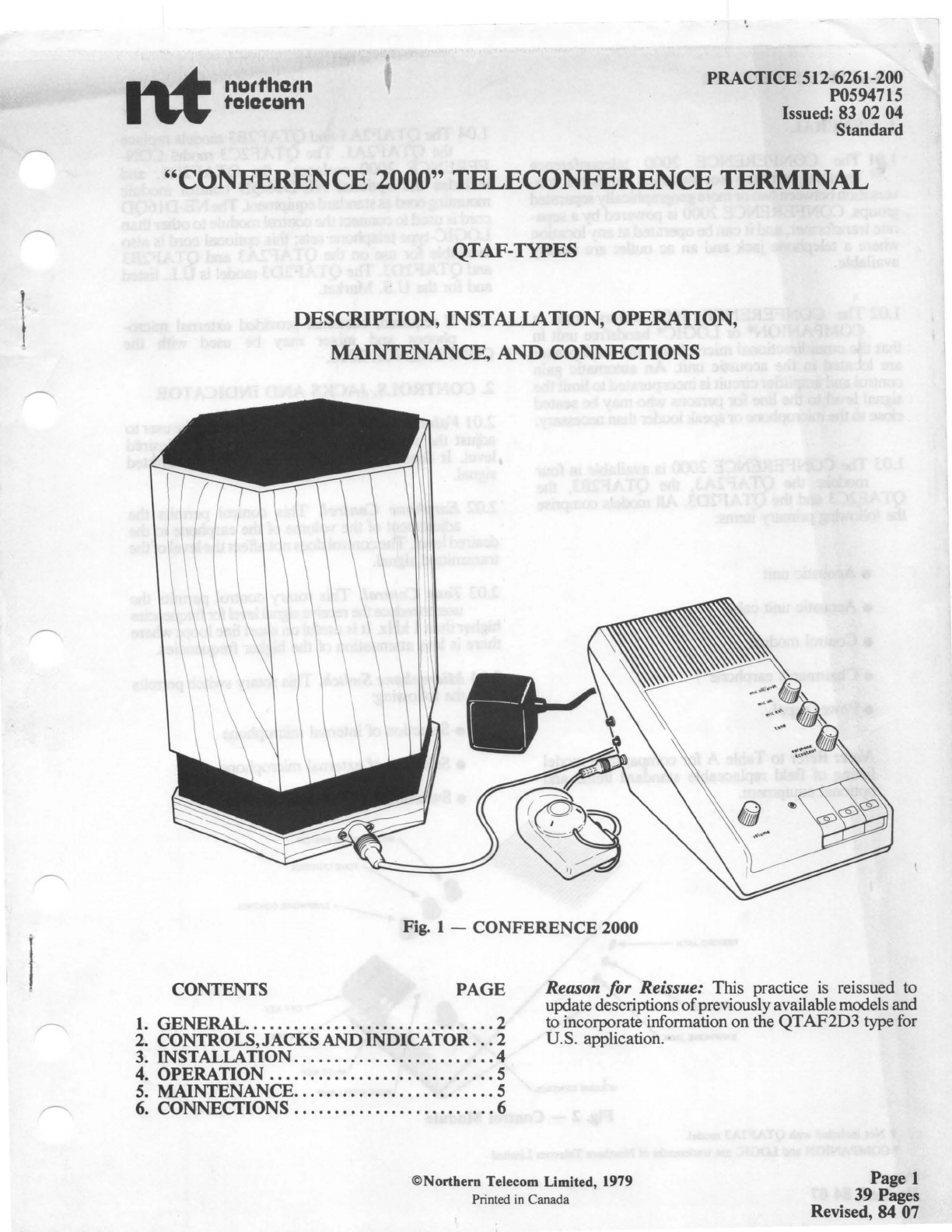
Fig. 1 -
CONFERENCE
2000
CONTENTS
PAGE
1.
GENERAL
..
...
..............
. . .
....
.
....
2
2.
CONTROLS,JACKSANDINDICATOR
.
..
2
Reason for Reissue: This practice
is
reissued to
update descriptions
of
previouslyavailable models and
to incorporate information on the
QT
AF2D3
type for
U.S. application.
3.
INSTALLATION
..................•......
4
4.
OPERATION
............................
5
5. MAINTENANCE
.........................
5
6. CONNECTIONS
.........................
6
©Northern Telecom Limited, 1979
Printed in Canada Page 1
39 Pages
Revised, 84 07
PRACTICE 512-6261-200
1.
GENERAL
1.01 The
CONFERENCE
2000
teleconference
terminal permits voice-switched handsfree con-
versationbetweentwo
or
more geographicallyseparated
groups.
CONFERENCE
2000 is powered
by
a sepa-
rate transfonner, and it
can
be operated
at
anylocation
where a telephone
jack
and an ac outlet are readily
available.
1.02 The
CONFERENCE
2000
differs from a
COMPANION*
or
LOGIC*
handsfree unit in
that the omnidirectional microphone and loudspeaker
are located in the acoustic
unit
An automatic gain
control and amplifier circuitis incorporatedtolimitthe
signal level to the line for persons who may be seated
close tothe microphone
or
speak louder than necessary.
1.03 The
CONFERENCE
2000
is available in four
models: the Q_TAF2A3, the
QTAF2B3,
the
QTAF2C3
and the
QTAF2D3.
All models comprise
the following primary items:
• Acoustic unit
• Acoustic unit cable
• Control module
• Chairman's earphone t
• Power supply.
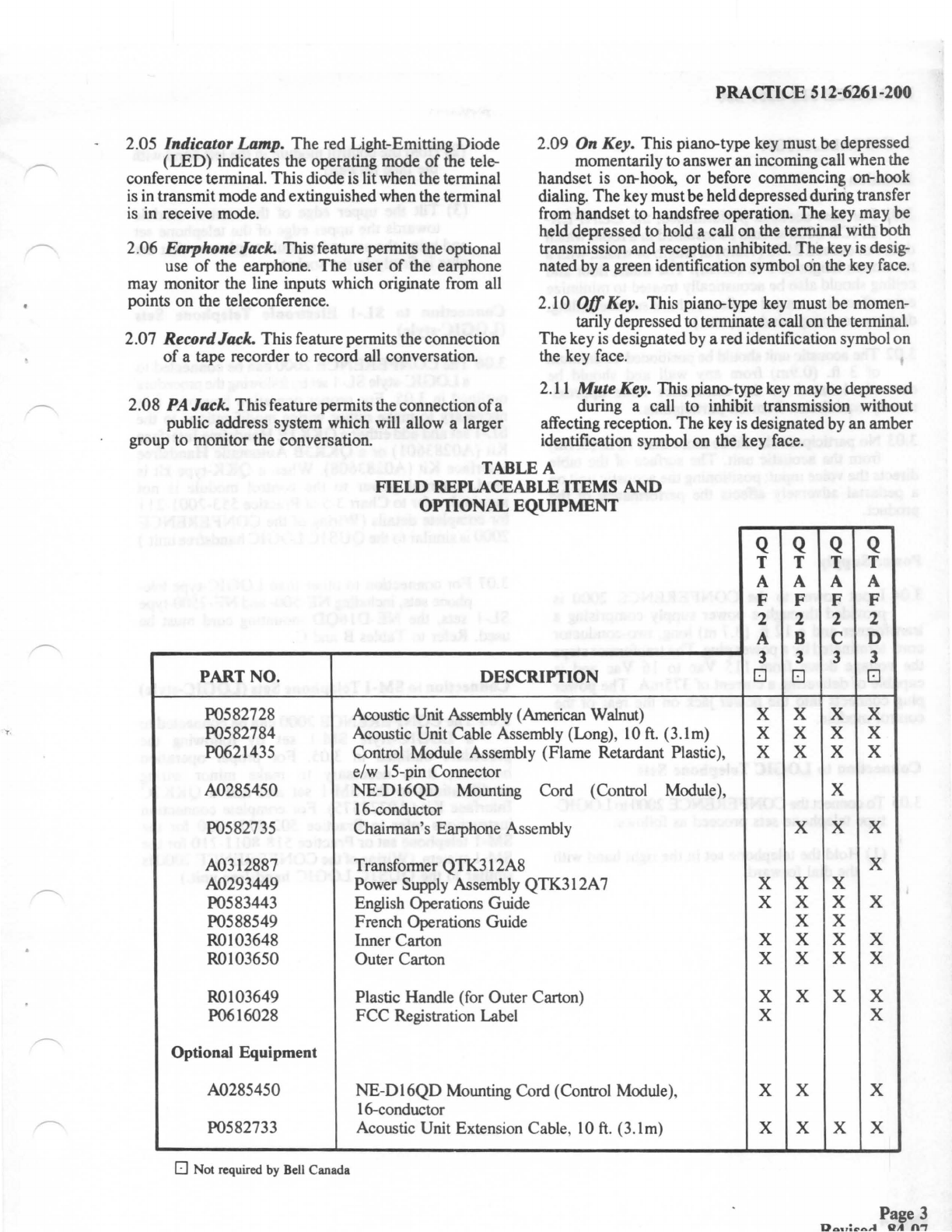
Note: Refer to Table A for comparative model
listing
of
field replaceable standard items and
optional equipment
,
..
~-~-
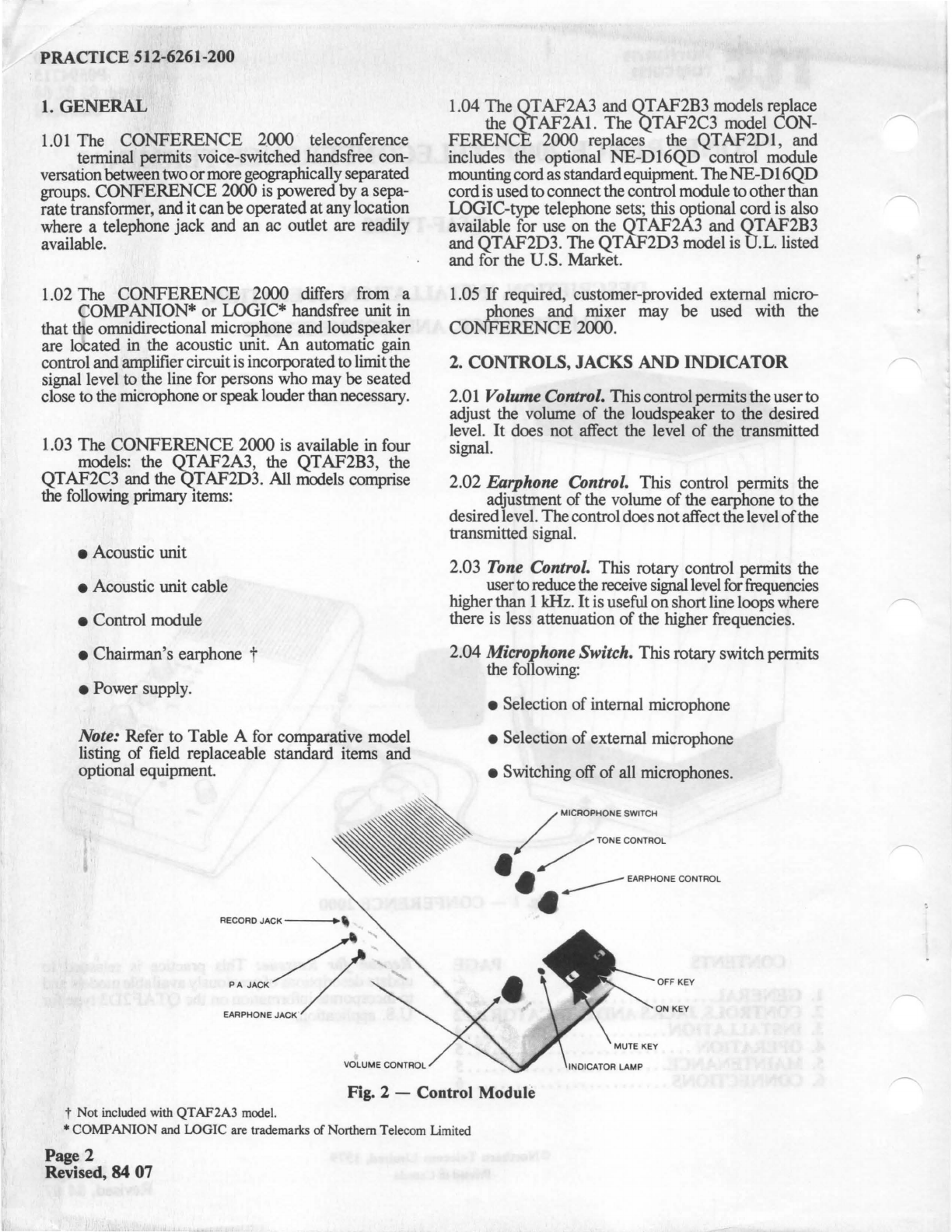
EARPHONE JACK
VOLUME CONTROL
1.04 The
OTAF2A3
and
QTAF2B3
models replace
the
OT
AF2Al.
The
QT
AF2C3
model
CON-
FERENCE
2000 replaces the
QTAF2D1,
and
includes the optional
NE-D16QD
control module
mountingcordas standardequipmentThe
NE-D
16QD
cordis usedto connectthe control module tootherthan
LOGIC-type telephone sets; this optional cord is also
available for use on the
QT
AF2A3
and
OT
AF2B3
and
QTAF2D3.
The
QTAF2D3
model is 0.L. listed
and for the U.S. Market.
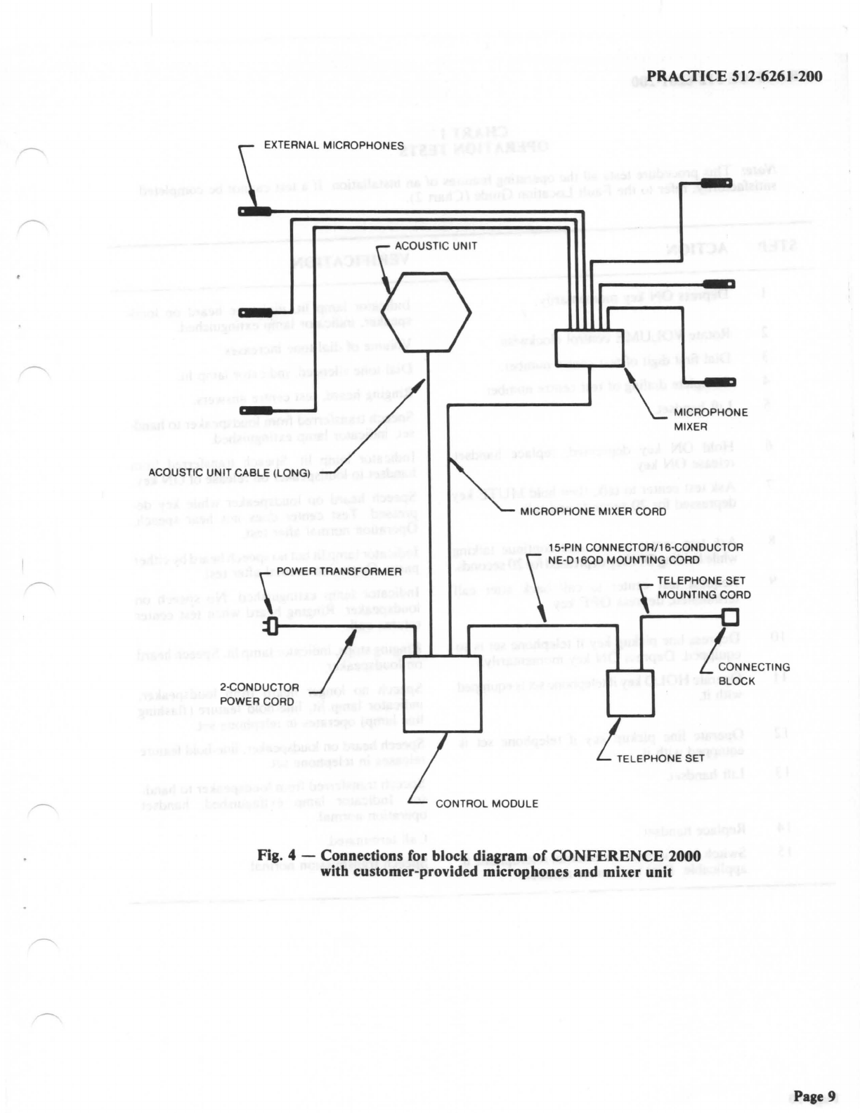
1.05 If required, customer-provided external micro-
phones and mixer may
be
used with the
CONFERENCE
2000.
2. CONTROLS, JACKS
AND
INDICATOR
2.01 Volume Control. Thiscontrol permitstheuserto
adjust the volume
of
the loudspeaker to the desired
level. It does not affect the level
of
the transmitted
signal.
2.02 Earphone Control. This control permits the
adjustment
of
the volume
of
the earphone to the
desiredlevel. Thecontrol does
not
affectthelevel
of
the
transmitted signal.
2.03 Tone Control. This rotary control permits the
usertoreduce the receive signal level
for
frequencies
higherthan 1kHz.
It
is useful
on
shortline loops where
there is less attenuation
of
the higher frequencies.
2.04 Microphone Switch. This rotary switch permits
the following:
• Selection
of
internal microphone
• Selection
of
external microphone
• Switching off
of
all microphones.
/
MICROPHONE SWITCH
/ TONE CONTROL
• •
-----
EARPHONE CONTROL
• OFF KEY
ON KEY
Fig. 2 -Control Module
t Not included with QTAF2A3 model.
•COMPANION
and LOGIC are trademarks ofNorthern Telecom Limited
Page 2
Revised,
84
07
~-
2.05 Indicator Lamp.
The
red Light-Emitting
Diode
(LED)
indicates the operating mode
of
the tele-
conference terminal.
This
diode is litwhen the terminal
is
in transmitmode and extinguished when the terminal
is in receive mode.
2.
06
Earphone Jack. This feature permits theoptional
use
of
the earphone.
The
user
of
the earphone
may
monitor the line inputs which originate from all
points
on
the teleconference.
2.
07
RecordJack. This feature permits the connection
of
a tape recorder to record all conversation.
2.08
PA
Jack. Thisfeature permits the connection
ofa
public address system which will allow a larger
group to monitor the conversation.
PRACTICE 512-6261-200
2.09 On Key. This piano-type key must be depressed
momentarily to answer an incomingcall when the
handset is on-hook, or before commencing on-hook
dialing.
The
key mustbe held depressedduririg transfer
from handset to handsfree operation.
The
key
may
be
held depressed to hold a call on the terminal with both
transmission and reception inhibited
The
key is desig-
nated by a green identification symbol o·n the key face.
2.
10
Off
Key. This piano-type key must be momen-
tarily depressed to terminate a call onthe terminal.
The
key is designatedby a red identification symbol
on
the key face.
2.11 Mute Key. This piano-type key may
be
depressed
during a call
to
inhibit transmission without
affecting reception.
The
key is designated by
an
amber
identification symbol
on
the key face.
TABLE
A
PART
NO.
P0582728
P0582784
P0621435
A0285450
P0582735
A0312887
A0293449
P0583443
P0588549
R0103648
R0103650
R0103649
P0616028
Optional
Equipment
A0285450
P0582733
D Not required by Bell Canada
FIELD
REPLACEABLE
ITEMS
AND
OPTIONAL
EQUIPMENT
DESCRIPTION
Acoustic Unit Assembly (American Walnut)
Acoustic Unit Cable Assembly (Long),
10
ft
. (3.
lm)
Control Module Assembly (Flame Retardant Plastic),
e/w 15-pin Connector
NE-D16QD
Mounting Cord (Control Module),
16-conductor
Chairman's Earphone Assembly
Transformer QTK.3 l 2A8
Power Supply Assembly QTK.3 l 2A7
English Operations Guide
French Operations Guide
Inner Carton
Outer Carton
Plastic Handle (for Outer Carton)
FCC
Registration Label
NE-D16QD
Mounting Cord (Control Module),
16-conductor
Acoustic Unit Extension Cable,
10
ft.
(3.
lm)
Q
T
A
F
2
A
3
□
X
X
X
X
X
X
X
X
X
X
X
Q Q Q
T T T
A A A
F F F
2 2 2
B C D
3 3 3
□
□
X X X
X X X
X X X
X
X X X
X
X X
X X X
X X
X X X
X X X
X X X
X
X X
X X X
Page
3
D.au:ra,1
QA
n"T
PRACTICE
512-6261-200
3.
INSTALLATION
Location
3.01
For
best acoustic performance, the
CONFER-
ENCE
2000 should be installed
in
a room which
does notexceed
25
ft.
(7
.6m)
in
length orwidth, with a
maximum height of 9
ft.
(2.7m). The walls, floor and
ceiling should also be acoustically treated to minimize
echo effect (i.e., carpeton floor, a hard surface ceiling,
drapery covering windows, etc.).
3.02 The acoustic unit should be positioned a minimum
of 3
ft.
(0.9m) from any wall and should be
centrally located on the conference table approxi-
mately equidistant
from
all participants.
3.03
No
participant should be more than 10
ft.
(3.lm)
from the acoustic unit. The surface of the table
directs the voice input; positioning the acoustic uniton
a pedestal adversely affects the performance
of
the
product.
Power Supply
3.04 Input power to the
CONFERENCE
2000
is
provided through a power supply comprising a
transformer and a 12
ft.
(3.7 m) long, twerconductor
cord terminatedbya powerplug. The tranformer steps
the voltage down from 115 Vac to
16
Vac and is
capable ofdelivering a current of 375mA. The power
plug connects into the power jack on the rear
of
the
control module.
Connection to LOGIC Telephone Sets
3.05 Toconnect
the
CONFERENCE2000 to LOGIC-
type telephone sets proceed as follows:
(1) Hold the telephone set in the right hand with
the dial forward.
Page 4
Reissued,
84
07
(2) Hold the control module in the left hand with
the face forward.
(3) Tilt the upper edge of the control module
towards the upper edge
of
the telephone set
and bring the set and module togther so that the
plug
is
firmly in the socket.
Connection
to
SL-1 Electronic Telephone Sets
(LOGIC-style)
3.06 The
CONFERENCE
2000 can be connected to
a LOGIC-style SL-1 setby
following
the
procedure
outlined in 3.05.
For
proper operation however, it is
necessary to make minor wiring modifications to the
SL-1 set and add either a Q
KK
1E Handsfreelnterface
Kit (A0283601) or a QKK3B Automatic Handsfree
Interface Kit (A0283608). When a QKK-type kit
is
used, external power to the control module
is
not
required; refer to Chart
3-5
ofPractice 553-2001-211
for complete details (Wiring
of
the
CONFERENCE
2000
is
similarto the
QUSlC
LOGIC
handsfree unit.)
3.07
For
connection to other than LOGIC-type tele-
phone sets, including NE-500- and NE-2500-type
SL-1 sets, the
NE-D16QD
mounting cord must be
used. Refer to Tables B and C.
Connection
to
SM-1 Telephone Sets (LOGIC-style)
3.08 The
CONFERENCE
2000 canbe connected to
a LOGIC-style SM-1 set by following the
procedure outlined in 3.05.
For
proper operation
however, it
is
necessary to make minor wiring
modifications to the SM-1 set and add a QKK2C
Interface Kit (A0272575).
For
complete connection
instructions refer to Practice 502-8771-200 for the
SM-1 telephone setor Practice 518-8011-210 for the
SM-1 system. (Wiringofthe
CONFERENCE
2000
is
similar to the
QUSlC
LOGIC handsfree unit.)
External Microphones
3.09 When the background noise level
is
so
high
that
the called party may have difficulty hearing,
external microphones located in closerproximity tothe
participant may improve the transmission quality.
When more than one external microphone (customer-
provided)
is
essential, a standard microphone mixer
(customer-provided)
is
required.
Notes: Customer-provided microphones should
meet the following specifications:
• Dynamic
• 10,000 ohm impedance
• 1/4 in. (6.4mm) plug.
Although 600-ohm, electret-type lapel micro-
phones perform well, the battery requirement
(3- to 6-houroperational use) may lead
to
frequent
battery replacement.
3.10 The microphone mixer should be centrally
located, adjacent to the acoustic unit. This ensures
that the external microphones are positioned approxi-
mately equidistant from the acoustic unit.
Note: Commercially available active mixers
(equipped with self-contained amplification cir-
cuits) can be connected to the
CONFERENCE
2000 mixer jack located at the back
of
the control
unit. When external microphones are
in
use, the
microphone switch on the front
of
the control unit
must be set
to
the mic ext position.
3.
11
When the microphone mixer cable is not long
enough to provide a central location for the
acoustic unit, an add-on extensioncord
will
be required.
PRACTICE 512-6261-200
3.12 On completion
of
the
CONFERENCE
2000
installation, the operation testsdescribed
in
Chart 1
must be performed
4. OPERATION
4.01
For
best operation, the following distance and
speech guidelines should be observed:
• Conference participants should
be
seated not
closer than 3
ft
(0.9m) or further than
IO
ft
(3
.1
m)
from the acoustic
unit
• Speech should be
at
normal conversation level.
Lowerlevels of
SJlCech
donotoperatethe voice
switching circuit and, consequently, are not
transmitted Thelevel
of
speechmustbe raised
as the distance from the acoustic unit
is
increased.
Note: The voice-switching circuit permits trans-
mission
of
speech in one direction at a time. The
circuit switches to transmit when you speak and
to receive when the distant party responds.
4.02 The acoustic unit represents the called party.
Speech should be directed toward the acoustic
unit at all times. Speech directed away from the unit
sounds hollow at the called party location.
S.
MAINTENANCE
5.01 If the
CONFERENCE
2000 must be returned
for repair, itshould be packaged using the cartons
listed in Table A to protect against damage during
shipping.
5.02 The
CONFERENCE
2000 should be treated as
a piece
of
fine
furniture (especially the acoustic
unit), and should not be subjected to temperature
extremes during use, storage
or
shipment
Page 5
PRACTICE 512-6261-200
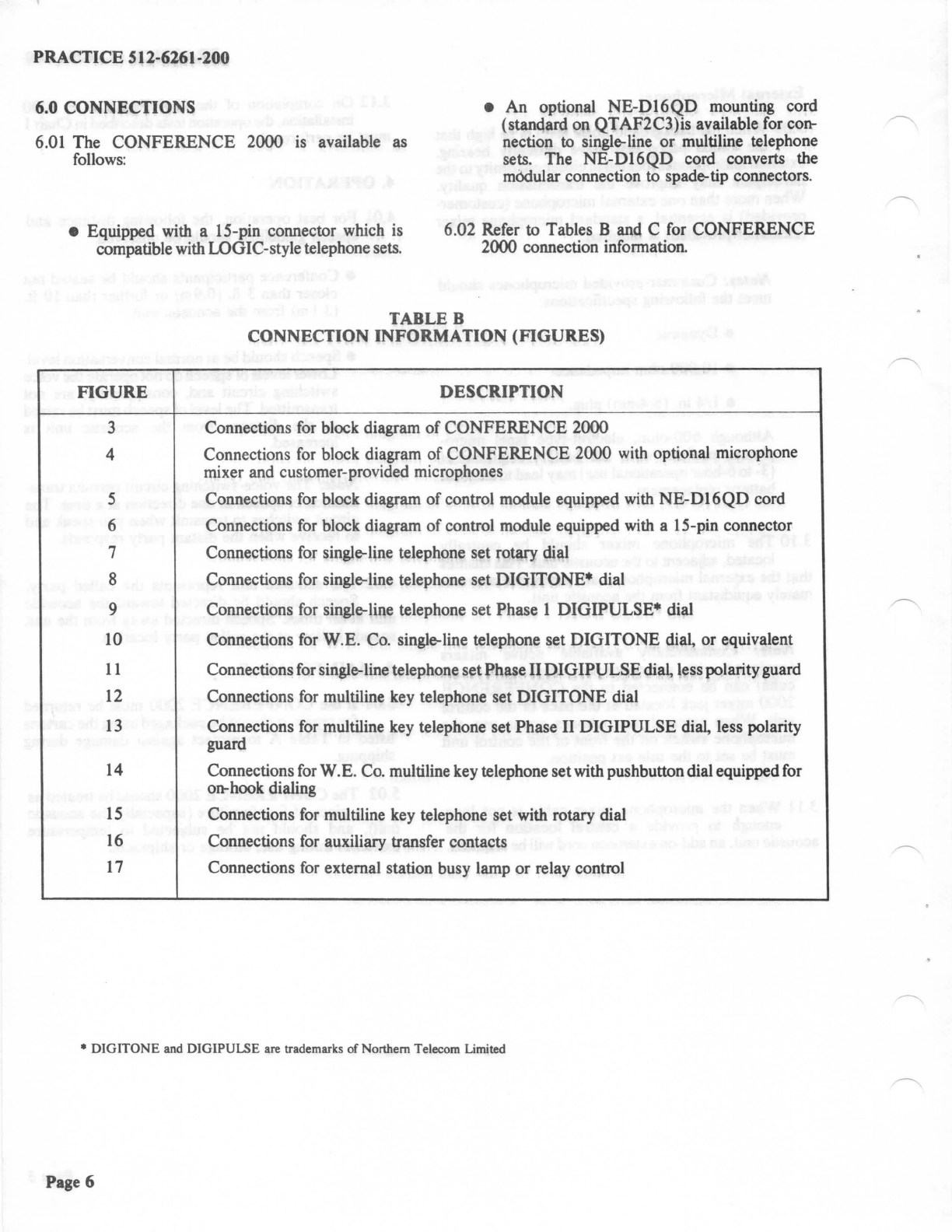
6.0 CONNECTIONS
6.01 The
CONFERENCE
2000 is available as
follows:
• An optional
NE-D16QD
mounting cord
(standard on QTAF2C3)is available for con-
nection to single-line
or
multiline telephone
sets. The
NE-D16QD
cord converts the
modular connection to spade-tip connectors.
• Equipped with a 15-pin connector which is
compatible with LOGIC-style telephone sets. 6.
02
Refer
to Tables B and C for
CONFERENCE
2000 connection information.
TABLE B
CONNECTION INFORMATION
(FIGURES)
FIGURE
DESCRIPTION
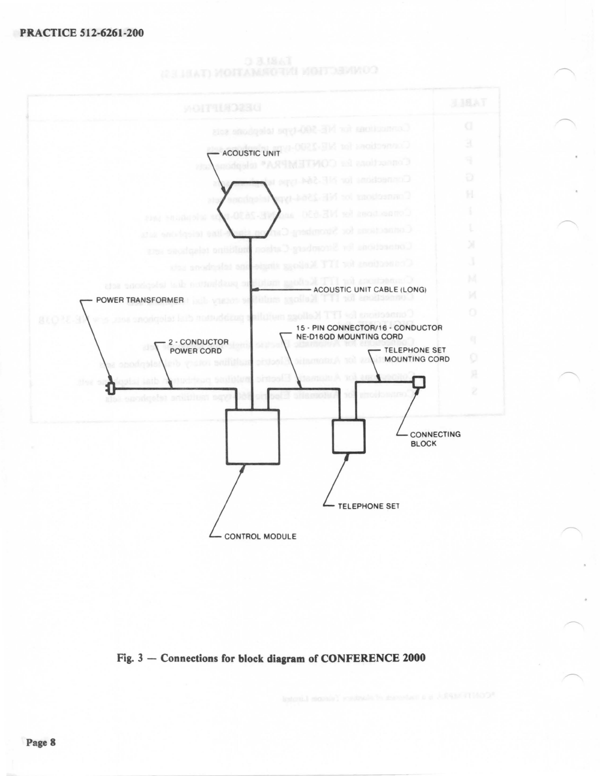
3 Connections for block diagram
of
CONFERENCE
2000
4 Connections
for
block diagram
of
CONFERENCE
2000 with optional microphone
mixer and customer-provided microphones
5 Connections for block diagram
of
control module equipped with
NE-D16QD
cord
6 Connections for block diagram
of
control module equipped with a 15-pin connector
7 Connections for single-line telephone set rotary dial
8 Connections
for
single-line telephone set
DIGITONE*
dial
9 Connections
for
single-line telephone set Phase 1 DIGIPULSE* dial
10
Connections for W.E. Co. single-line telephone set
DIGITONE
dial, or equivalent
11
Connections for single-line telephone setPhase
II
DIGIPl]LSE
diai
lesspolarityguard
12 Connections for multiline key telephone set
DIGITONE
dial
13
Connections for multiline key telephone set Phase II
DIGIPULSE
di~
less polarity
guard
14 Connections
for
W.E. Co. multiline key telephone setwith pushbuttondial equippedfor
on-hook dialing
15
Connections for multiline key telephone set with rotary dial
16
Connections for auxiliary transfer contacts
17
Connections
for
external station busy lamp
or
relay control
•
DIGITONE
and DIGIPULSE are trademarks of Northern Telecom Limited
Page 6
PRACTICE 512-6261-200
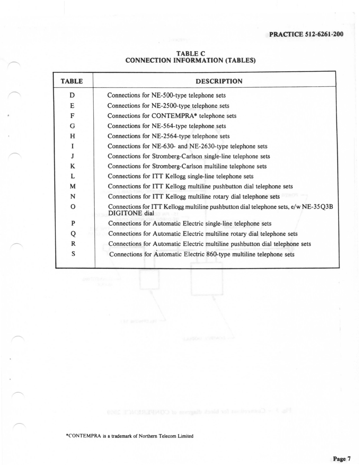
TABLE C
CONNECTION INFORMATION (TABLES)
TABLE DESCRIPTION
D Connections for NE-500-type telephone sets
E Connections for NE-2500-type telephone sets
F Connections for
CONTEMPRA*
telephone sets
G Connections
for
NE-564-type telephone sets
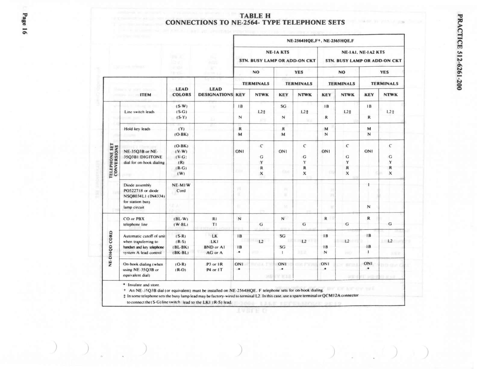
H Connections for NE-2564-type telephone sets
I Connections
for
NE-630- and NE-2630-type telephone sets
J Connections for Stromberg-Carlson single-line telephone sets
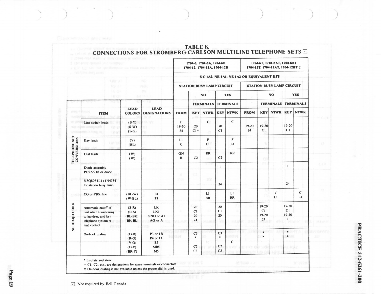
K Connections for Stromberg-Carlson multiline telephone sets
L Connections for
ITT
Kellogg single-line telephone sets
M Connections for
ITT
Kellogg multiline pushbutton dial telephone sets
N Connections for
ITT
Kellogg multiline rotary dial telephone sets
0 Connections for
ITT
Kellogg multiline pushbuttondial telephone sets, e/w
NE-35Q3B
DIGITONE
dial
p Connections for Automatic Electric single-line telephone sets
Q Connections
for
Automatic Electric multiline rotary dial telephone sets
R Connections for Automatic Electric multiline pushbutton dial telephone sets
s Connections for Automatic Electric 860-type multiline telephone sets
*CONTEMPRA
is
a trademark of Northern Telecom Limited
Page 7
PRACTICE 512-6261-200
Page 8
ACOUSTIC UNIT
.,._
_____
ACOUSTIC UNIT CABLE (LONG)
POWER TRANSFORMER
2 · CONDUCTOR
POWER CORD
CONTROL MODULE
15 · PIN CONNECTOR/16 · CONDUCTOR
NE·D16QD MOUNTING CORD
TELEPHONE
SET
MOUNTING CORD
TELEPHONE
SET
CONNECTING
BLOCK
Fig. 3 - Connections for block diagram
of
CONFERENCE 2000
PRACTICE 512-6261-200
EXTERNAL MICROPHONES
ACOUSTIC UNIT
ACOUSTIC UNIT CABLE (LONG)
\ POWER TRANSFORMER
2-CONDUCTOR
POWER CORD J
MICROPHONE MIXER CORD
15-PIN CONNECTOR/16-CONDUCTOR
TELEPHONE
SET
\
NE·D16QD MOUNTING CORD
\ MOUNTING CORD
LONNECTING
BLOCK
TELEPHONE
SET
CONTROL MODULE
Fig. 4 - Connections for block diagram
of
CONFERENCE 2000
with customer-provided microphones and mixer unit
Page 9

PRACTICE 512-6261-200
CHART I
OPERATION TESTS
Note: This procedure tests all the operating features
of
an installation. If a test
cannot
be completed
satisfactorily. refer to the
Fault
Location
Guide
(Chart
2).
STEP
2
3
4
5
6
7
8
9
10
11
12
13
14
15
Page
10
ACTION
Depress ON key momentarily.
Rotate
VOLUME
control clockwise.
Dial first digit
of
test centre number.
Complete dialing
of
test centre number.
Lift handset.
Hold
ON
key depresse
d.
replace handset.
release
ON
key.
Ask test center to talk. then hold
MUTE
key
depressed for
20
seconds and talk.
Ask test centre to talk and continue talking
while holding
ON
key depressed for 20 seconds.
Request test center to call back after call
terminated, depress
OFF
key.
Depress line pickup key if telephone set
is
so
equipped. Depress
ON
key momentarily.
Operate
HOLD
key iftelephone set
is
equipped
with
it.
Operate
line pickup key if telephone set
1s
equipped with
it.
Lift handset.
Replace handset.
Switch from internal to external microphone if
applicable. Dial test center number.
VERIFICATION
Indicator lamp lit. dial tone heard on loud-
speaker. indicator lamp extinguished.
Volume
of
dial tone increases.
Dial tone silenced. indicator lamp lit.
Ringing heard. test centre answers.
Speech transferred from loudspeaker to hand-
set. indicator lamp extinguished.
Indicator lamp lit. Speech transferred from
handset to loudspeaker on release
of
ON key.
Speech heard
on
loudspeaker while key de-
pressed.
Test
center does not hear speech.
Operation normal after test.
Indicator lamp lit but no speech heard
by
either
party. Operation normal after test.
Indicator lamp extinguished.
No
speech on
loudspeaker. Ringing heard when test center
returns call.
Ringing stops. indicator lamp lit. Speech heard
on loudspeaker.
Speech no longer heard from loudspeaker.
indicator lamp lit. line-hold feature (flashing
line lamp) operates
in
telephone set.
Speech heard on loudspeaker. line-hold feature
releases
in
telephone set.
Speech transferred from loudspeaker to hand-
set. Indicator lamp extinguished. handset
operation normal.
Call terminated.
Speech transmission normal.
PRACTICE 512-6261-200
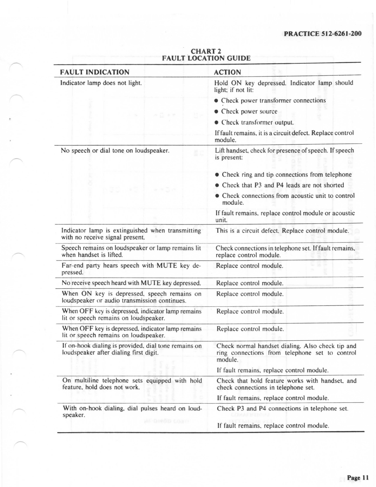
CHART2
FAULT .LOCATION
GUIDE
FAULT INDICATION
Indicator lamp does not light.
No
speech
or
dial tone on loudspeaker.
Indicator lamp
is
extinguished when transmitting
with no receive signal present.
Speech remains
on
loudspeaker
or
lamp remains lit
when handset
is
lifted.
Far-end party hears speech with
MUTE
key de-
pressed.
No
receive speech heard with
MUTE
key depressed.
When
ON
key
is
depressed. speech remains on
loudspeaker
or
audio transmission continues.
When
OFF
key
is depressed. indicator lamp remains
lit
or
speech remains on loudspeaker.
When
OFF
key
is
depressed. indicator lamp remains
lit
or
speech remains on loudspeaker.
If on-hook dialing
is
provided. dial tone remains on
loudspeaker after dialing first digit.
On
multiline telephone sets equipped with hold
feature. hold does not work.
With on-hook dialing. dial pulses heard on loud-
speaker.
ACTION
Hold
ON
key depressed. Indicator lamp should
light; if not lit:
• Check power transfonner connections
•
Che
ck power source
• Check transformer output.
If
fault remains.
it
is
a circuit
defect
Replace control
module.
Lift handset. check for presence
of
speech.
If
speech
is
present:
• Check ring and tip connections from telephone
• Check that P3 and P4 leads are not shorted
• Check connections from acoustic unit to control
module.
If
fault remains. replace control module or acoustic
unit.
This
is
a circuit defect. Replace control module.
Check connections
in
telephone set.
If
fault remains.
replace control module.
Replace control module.
Replace control module.
Replace control module.
Replace control module.
Rt-place
co
ntrol module.
Check normal handset dialing. Also check tip and
ring connections from telephone set to control
module.
If
fault remains. replace control module.
Check that hold feature works with
handset
and
check connections in telephone set.
If
fault remains. replace control module.
Check P3 and P4 connections
in
telephone set.
If
fault remains. replace control module.
Page
11

""'
•
~
-
N
)
~
l,IJ
r,)
ell z
l,IJ
0
z
;;;
0
a:
:c
l,IJ
"";;,,
l,IJ
z
-I
0
~u
Q
a:
0
u
Q
0
,c
Q
UJ
z
)
TABLED
CONNECTIONS
FOR
NE-500- TYPE
TELEPHONE
SETS
NE-500C/D,
NE-5548:j:
NE-500UM
NE-500R/S
REWIRED
FOR
NE-500LR (nondial)
NE-500RR
(nondial)
A
LEAD
CONTROL
NE-IAI,
NE
-
IA2
KTS
INDIVIDUAL
OR
BRIDGED
CO
OR
PBX
LINE
ITEM
LEAD
LEAD
SET
NTWK
SET NTWK SET
NTWK
COLORS
DESIGNATION
TERMINALS
TERMINALS
TERMINALS
TERMINALS
TERMINALS
TERMINALS
Line switch leads
(S-W)
G 5
(S-G)
Cl
Cl
t
Telephone
line leads
(R)
R
L2 L2 L2
(Gl
T F F G
Dial
leads
tW)
RR
RR
(W)
C2
C2
CO
or
PBX
1BL-W) RI
L2
L2
3
Telephone
line
(W-BL)
Tl
RR
RR E2
Automatic
cutoff
of
(S-R)
LK
G 5 4
unit
when
transfer- t R-Sl
LKI
Cl
Cl
•
ring to
hand
set and
tBL
-BKi
GND
or
Al
G 5
El
ke~
telephone system (BK-Bl.)
AG
or
A •
*or
LI~
6 5
A lead control
(O
-
R)
P3
or
I R
C3 C3
6
(R
-
O1
P4
or
IT
• • I
On-hook
dialing
CV
-
O)
B5
C C
CO
-Vi MB5 C2
C2
cBR-
YI
MS
C3
C3
• Insulate and store.
t
Lead
~ designated
CI
.
C2.
etc.
in
table must
oe
bridged
to
leads with identical designations using
QCM
12A
co
nnectors
or
spare
terminals.
:I:
On
-hook dialing
is
not available with the
NE
-
5548
telephone set.
-::
Wh~n A lead control
is
required
) ) )
""'
~
Q
-
("'l
rt,
u.
-
N
I
0'I
N
0'I
-
I
N
g

?
-
c.,
) )
ti
"'
"' z
wO
z
;;;
OCII:
::c
w
Cl.
;;i.
u.;
z
.J
0
j::
u
Q
Cl:
0
I;.,
Q
0'
~
Q
w
z
) ) ) )
TABLE E
CONNECTIONS
FOR
NE-2500- TYPE
TELEPHONE
SETS
NE-2S00D.NE-2SOODQD§
NE-2SOOSQA
..
NE-I
Al
OR
NE-I A2 KTS
INDIVIDUAL
OR
BRIDGED
CO
OR
PBX
LINE
ITEM
LEAD
LEAD
SET NTWK SET
NTWK
COLORS
DESIGNATIONS
TERMINALS TERMINALS
TERMINALS
TERMINALS
Linc
'"
itch
kad,
(S-W)
G
(S-GI
Cl+
CO nr
PBX
(GI
T
RR
Tel
ep
hone
lane
NE
-.lSQ.lB
.-
B
1.-B.2
.
or
(0-BK)
C
NE
-.lSQ.lL.-LI
.-
U
(V
-
W)
C2
DIGITONE
dial for
1V
-
G)
LI
on-hook dialing.
(R)
y
(R
-
G)
R
(WI
X
Teh:phone line
(BL
-
W)
RI
L2
E2
to
unit
(W
-BL)
Tl
LI 5
Automatic
cutoff
of
unit (S-R)
LK
G 4
when transferring. tn hand-
(R
-
S)
LKI
Cl
*
set and key telephone
(BL-BK)
GND
or
Al
G 3
system A lead ,:ontml
(BK
-BLI
AG
or
A *
El
;
On-hook dialing. (when
(0-R)
P3
or
IR
C2 6
using.
NE
-.
•5Q.lB
nr
(R
-
O)
P4
or
IT
* 2
equi,
aknt
dial I
• Insulate and store.
+
CI
. C2.
ell.:
.. arc designations for
spare
terminals
or
connectors.
; Insulate if not used for A lead control.
;i
On
-hook dialing. not available unless
proper
DIG
!TONE
dial is used.
The
N E-
2500D
telephone
se
t requires a 4--conductor line
cord
.
**
The
NF.
-
2500SQA
telephone
set uses an
NE
-
35Q3L2
DIGITONE
dial.
)
-a
~
q
-
n
m
(A
-
N
c:rl
N
c,\
-
I
N
g

?
-
•
)
...
r,,
~z
Iii
0
Zrn
i:i
Do
>
Iii
z
-10
~u
Q
,:ii:
0
u
Q
~
IO
-
Q
g;i
z
)
TABLE F
CONNECTIONS
FOR
CONTEMPRA
TELEPHONE
SETS
NE-44AOR
QSKIOOA/B,
QSK2l00A/B
,
QSKl9IB,
QSK2l91B
t
EQUIV
Al.ENI
CONNECTING INDIVIDUAL
OR
BRIDGED
NE-IAI,
NE
-
IA2
BLOCK
CO
OR
PBX
LINE
KTS
LEAD LEAD
SET
NTWK
SET
NTWK
ITEM
COLORS
DESIGNATION
TERMINAL TERMINALS TERMINALS TERMINALS TERMINALS
(S)
L3 L3
Line switch leads (S-Y) G G
(S-BR)
GI
GI
(R) R I
xi
(or C)
xi
(or
C)
(G)
T 2
LI
LI
External connect-
ion with
NE
-
D6QB
(Y)
Al
5 G G
mounting cord (BK) A 4 •
(or
Y) y
(W)
LKI 3
GI GI
(BL) § • •
CO
or
PBX
(BL-W)
RI
§ I
xi
(
or
C)
xi
(
or
C)
Telephone line
(W
-BL)
Tl
2
LI LI
Automatic cutoff unit when (S-R) LK 5 G G
transferring to handset
(R
-S) LKI 3
GI GI
and key telephone system (BL-BK)
GNDorAI
5 G G
system A lead control
(BK
-BL)
AG
or
A 4 • y
~hook
dialing
(~R)
P3
or
IR
• •
(R
-
0)
P4
or
IT
• •
• Insulate and store.
t On-hook dialing
is
not available with these telephone sets.
i This terminal applies only to
DIGITONE
sets: use network terminal C otherwise.
§
For
wall mounted rotary dial sets, connect ringer line lead (red) to terminal
L2
and connect L2 to C using an
NE
-
Ml
W cord.
For
bridged ringing. connect ringer
across R and T
of
the telephone line.
) ) ) ) )
.,,
~
q
-
n
rn
u-
-
N
I
0\
N
0\
-
I
N
g

l
-
u,
) )
I-
"'
el
z
I.I.I
0
z;;;
0 Ill:
:c
I.I.I
II.
..
I.I.I
z
..I 0
~u
Q
er:
0
u
Q
0'
'°
Q
.ii
z
) ) ) )
TABLE G
CONNECTIONS
TO
NE-5664- TYPE
TELEPHONE
SETS
NE-564HQAA.
BA.
CA. DA. EA. FA. GA.
JA§
NE-IA KTS NE-IAI,
NE-IAl
KTS
STN. BUSY LAMP, ADD-ON LAMP STN. BUSY LAMP, ADD-ON
CKT
.
STATION
BUSY
LAMP
CIRCUIT
OR
ADD-ON
NO
YES NO YES
TERMINALS TERMINALS
TERMINALS
TERMINALS
LEAD LEAD
ITEM COLORS
DESIGNATIONS
KEY NTWK KEY NTWK KEY NTWK KEY
NTWK
(S.W)
18
SG
18
18
Line switch leads
(S.G)
1..2 1..2
u u
(S.Y) N N R R
Hold
key
leads (Y) R R M M
(0-BKt)
M M N N
Dial leads
(W)
RR
RR RR RR
(W)
ON ON ON ON
Diode Assembly
NE-MIW
I
P0522718
or diode Cord
NSQ8034LI ((N4384)
for
station busy
lamp circuit N
CO
or PBX (BL-W)
RI
N N R R
telephone line (W-BL)
Tl
RR RR
RR
RR
I
Automatic cutoff
of
unit (S.R) LK
18
SG
18
l
18
I
when transferring
10
(R-S) LKI
1..2
u u u
harusel
and
key
teleplu,e (BL-BK)
GNDorAI
18
SG
18
!
18
I
system A lead control (BK-BL)
AG
or A • I N I
(0-R)
P3 or IR
ONI
ONI
ONI
ONI
(R-O) P4 or
IT
• • • •
On-hook dialing (V-O)
BS
C C C C
(0-V)
MBS
ON
ON
ON ON
(BR-Y)
MS
ONI
ONI ONI
ONI
i
• Insulate and store.
t
In
some telephone sets this lead
is
(Y-BK):
NE-564HDRN.HDN
.
HBRN.NE
-
5548.NE-565HBRN.HDRN.LBRN.DRN.HQF.
:j:
Non-dial telephone sets. dial leads and on-hook dialing do not apply.
!i
Connections
for
the sets using this column are dependant on the vintage
of
the set wiring. therefore prior
10
connecting verify
1hat
the BL lead (
Y-BR)
from
1he
telepho
ne
set mounting cord
is
terminated on terminal I
of
the key terminal strip.
)
.,,
~
-
n
rr,
tA
-N
I
~
N
~
-
N
8
'"Cl
'=
-
°'
I-
..,
::lz
wO
z;;;
oai:
:rw
a.>
wz
...10
~
I.>
Q
ai:
0
I.>
Q
0'
'°
Q
Iii
z
) )
TABLE H
CONNECTIONS
TO NE-2564-
TYPE
TELEPHONE
SETS
NE-2564HQE,Ft.
NE-2565HQE.F
NE-
IA
KTS NE-IAI. NE-IA2 KTS
STN.
BUSY
LAMP
OR
ADD-ON
CKT STN. BUSY LAMP OR
ADD
-
ON
CKT
NO YES NO YES
TERMINALS TERMINALS TERMINALS
TERMINALS
LEAD
LEAD
ITEM
COLORS
DESIGNATIONS
KEY NTWK KEY NTWK KEY NTWK KEY
NTWK
(S.W)
18
SG
18 18
Line switch leads
(S.G)
L2f L2f
L2*
L2!
(S-Y)
N N R R
Hold
ke
y leads
(Y)
R R M M
(O.BK)
M M N N
(O.BK)
C C C C
NE-
35Q3B
or NE-
(V
-
W)
ONI ONI ONI
ONI
35Q381
DIGITONE
(V
-G : G G G G
dial for on-hook dialing (R) y y y y
(R-G)
R R R R
(WI
X X X X
Diode assembly
NE
-
MIW
I
P05227
I8
or
diode Cord
NSQ8034LI
(IN4334)
for station busy
lamp circuit N
CO
or
PBX
!Bl
-
Wt
RI N N R R
telephone line
(W
-BLI
Tl
G G G G
Automatic cutofT
of
unit 1S.R1 LK
18
SG
18
18
when tra,nsferring to
1R
-
S1
LKI
L1
L1
L2
L2
hand&et
and
ke)
· telepl,me (BL-BK)
BND
or
Al
18
SG
18 18
,ystem A lead control
(BK
-
Bl)
AG
or A • I N I
On-hook dialing cwhen
(0.R)
PJ
or
IR
ONI ONI ONI
ONI
usinl! NE-
JSQJB
or
!R
-
0)
P4 or
IT
• • • •
equivalent dial)
• Insulate and store.
+ An NE-35Q3B dial (or equivalent) must
be
installed on NE-
2564HQE
. F telephone sets
for
on-hook dialing.
!
In
some telephone sets the busy lamp lead may
be
factory-wired to terminal
L2
.
In
this case. use a spare
terminalorQCM
12A connector
toconnectthe(S.G)lineswitch
lead to the LKI
(R
-S) lead.
) ) ) ) )
.,,
~
q
-
n
l'T1
u,
-N
I
°'
N
°'
-
I
N
=
=

l
ft
-
....
)
Ill
.,
z z
0
!2
:z:
..
..
..
...
.
Ill_,
Ill
...
>
"' z
..
8
C
•
8
C
i
Q
"'
z
) ) ) ) )
TABLE I
CONNECTIONS
TO NE-630-
AND
NE-2630- TYPE
TELEPHONE
SETS
ITEM
CO
or
PBX
T...,,.,._
lino
Automlllic
cUIOlf'
d
uni1
whltn traMferrina
10
hand-
,.,
and
key
lelq,hone
sysum
A lead
~
O.hooll
dialina
• lna.alate and lk>re.
LEAD I
LEAD•
COLORS
DESIGNATIONS
(BL-WI
(W-
BLI
JS-RJ
IR-
SJ
(BL-BKI
(BK
-
BLI
10-Ri
IR-
0)
RI
Tl
LI(
1.1(1
GNDor
Al
AG
or
A
P3
o.-
IR
Nor
IT
NE
..
Je,NE~I
.
NE-6M.NE-6H
TYP£S
NE-IA KTS NE-
IAI.NE
-
IAl
KTS
SYN
.
■
USY
l.AMP
, ADD-ON
CKT
SYN
.
■
USY
UMP.
ADD-ON CKT
NO YES NO
YES
TERMINALS
TERMINALS TERMINALS
TERMINALS
■
oARD
I
NTWK
I
■
oARD
I
NTWK
I
■
oARD
I
NTWK
I
■
oARD
I
NTWK
w
1B
Uw
X
onrinc
I u
..
z •irinc I u
..
X
ud
Y
RR
LI
L2
w
BB
RR
LI
L2
w
BB
RR
LI
G
w
BB
-..
RR
LI
L2
+ Thew teadl may tcnnina&t on
tmninals
othff
tha,
lhol,e
lilied
in
thi1
tabw dependina
on
the vint.aer
al
tM
tclephoM-
Id.
Refer
lO
the
wirina
cfiaaram
for
the leleph,ont
set
.
NE-16M. NE-16JI. NE-16M. NE-16J5.
NE-
26H.NE
-W 1,NE-J6M.NE-
W5
TYPES
NE-
IAKTS
NE
-
IAI.
NE
-
IAl
KTS
SYN
.
■
USY
LAMP
. ADD-ON
CKT
STN.
■
USY
LAMP. ADD-ON CKT
NO I YES I NO
YES
TERMINALS
I
TERMINALS
I
TERMINALS
TERMINALS
■
oARD
I
NTWK
I
■
oARD
I
NTWK
I
■
oARD
I
NTWK
■
oARD
I
NTWK
UxX
wirin, I
Uw
Z
•innt
Us,
X
andY
Wlri"C
2 2 2 I 2
10 10 10
JO
9 9 9 I q
. . . .
'
I I I I
6 6 6
~
II
JI
II
!
JI
12 12 12
I2
I
\
I
.,,
~
~
-
n
tr.I
UI
-N
'
~
N
~
-
'
N
e
e

?
-TABLE J
CONNECTIONS
FOR
STROMBERG-CARLSON
SINGLE-LINE
TELEPHONE
SETS[:]
00
S-C
5000.
S-C
5548+
S-C
2500D+
+ S-C
2554Bi
INDIVIDUAL
OR
BRIDGED
NE-IAI.
NE-IA2
OR
EQUIVALENT
KTS
CO
OR
PBX
LINE
FROM
TO
FROM
TO
FROM
TO
TERMINALS TERMINALS
TERMINALS
TERMINALS
TERMINALS
TERMINALS
LEAD
LEAD
ITEM
COLORS
DESIGNATIONS
SET
NTWK
SET
NTWK
SET
NTWK
SET
NTWK SET
NTWK
SET
NTWK
Line switch leads
1s.w,••
F G I LI G 3
...
(S-G)
LI
CJ+
LI
Cl
I
l,i,I
"'
"'z
l,i,I
0 Telephone line lead, (R) R
L1
L1
2
z;;;
(G)
T
LI
F
LI
I I G
0
ai:
=
l,i,I
o.>
l,i,I
z Dial leads
(W)
GN
RR
,.j
0
~
t.l
(W)
R C2
A Control leads A
LI~
CH
LI~
Al
G~
LI~
G~
CO
or PBX line (BL-W) RI
L1
L2
l
(W
-BL)
Tl
RR
I 3
Automatic cutoff
of
!S-R)
LK
G
LI
3
Q
riwhen~
(R
-
S)
LKI
Cl Cl
I
ai:
0 10 handset. and
key
(BL
-
BKI
GND
or
Al
G
LI
3
t.l telephone system A (BK-BLI
AG
or
A •
or
LI~
•
or
.
"r
LI~
Q
O'
,0
lead control
C'H
Q .
Lil
On-hook dialing
(0-R)
P3
or
IR
('3
•
z
(R
-
0)
P4
or
IT
•
(V-
0)
85
C'
(0-V)
M85
('2
fBR-Y)
MS
C'3
•
In
sulate and store.
+ Leads designated
C'
I.
C'2
. etc
..
must be bridged
10
leads with identical designations using QC'M 12A connectors or spare terminals.
i On-hook dialing not available.
~
Used only when A lead control
is
required.
••
On
1he
S-C 2.<~48 telephone set these colors are l
W)
and
(GI
.
t t On-hook dialing not available unless an NE-35
Q38
or
equivalent DIGITONE dial is used.
[:]
Not required by Bell Canada
) ) ) ) ) ) )
.,,
~
Q
-
n
tT.I
(A
-
N
I
0'I
~
-
I
N
g
) ) ) ) )
TABLE K
CONNECTIONS
FOR
STROMBERG-CARLSON
MULTILINE
TELEPHONE
SETS
C:J
l7M-6,
17M-6A. 17M-6B l704-6T, l704-6AT,
l704-68T
1704-12,
17M-llA.
1704-llB
1704-llT.
178'-llAT,
1704-llBT
*
5-C
IAl,
NE-IAI,
NE-IAl
OR EQUIVALENT KTS
STATION BUSY LAMP CIRCUIT STATION BUSY LAMP CIRCUIT
NO
YES NO YES
TERMINALS TERMINALS TERMINALS Tl:RMINALS
LEAD
LEAD
ITEM COLORS DESIGNATIONS FROM KEY NTWK KEY NTWK FROM KEY NTWK KEY NTWK
Linc switch leads (S-Y) F C C
(S-W)
19
-20 20 20
19
-20
19
-20 19-20
(S-G) 24
Cit
Cl
24
Cl Cl
I-
"'
~z
Key leads (Y)
LI
F F
wO
(BL) C
LI
LI
z;;;
0
a.:
:cw
II,,
;.
Dial leads
(W)
GN
RR RR
wz
..10
(W)
R C2 C2
~u
Diode assembly I I
P05
227 I8 or diode
NSQ8034LI ( I N4384)
for
station busy lamp 24 24
CO
or PBX hnc
(BlrW)
RI
LI
LI
C C
(W
-BL)
Tl
RR RR
LI
LI
Q
a.:
Automatic cutoff
of
(S-R)
LK
20 20
19
-20
19
-20
0
u unit when transferring
(R
-S) LKI
Cl Cl Cl Cl
Q to handset.
and
key
(BlrBK)
GNDorAI
20 20
19
-20 19-20
0
...
telephone system A (BK-
BL)
AG
or A 24 I
24
I
Q lead control
I.ii
z On-hook dialin~
(0-R)
P3
or
IR
C3
C3 • •
(R-O) P4 or
IT
• • • .
(V-O)
85
C C
(0-V)
MB5
C2 C2
(BR-Y)
MS
C3
C3
• Insulate and store.
t CI . C2. etc
..
are designations for spare terminals or connectors.
l *On-hook dialing
is
not
available unless the proper dial
is
used.
-
IC
[:]
Not required
by
Bell Canada
) )
.,,
~
~
-
n
m
CA
-
N
I
0'I
N
0'I
-
I
N
g

~
Ill
~
N
c:>
)
TABLE L
CONNECTIONS
FOR
ITT
KELLOGG
SINGLE-LINE
TELEPHONE
SETS(:]
K-500. K
-5
54 ; K-2500
tt
K-2554 ;
INDIVIDUAL
OR
BRIDGED
CO
OR
PBX
LINE
K-IAI,
K·IA2
,
NE·IAI
,
NE·IA2
OR
EQUIVALENT KTS
FROM
TO
FROM
TO
FROM
TO
TERMINALS TERMINALS
TERMINALS
TERMINALS
TERMINALS
TERMINALS
LEAD
LEAD
ITEM COLORS
DESIGNATIONS
SET
NTWK
SET NTWK SET NTWK SET NTWK SET NTWK SET
NTWK
Line
swi
tch leads
,s.w,••
F G F G G J
(S.G)
LI
Cl
t
LI
Cl
I
~.,,
~z
Telephone
line
lead: (R) R
l2
l2
2
""
0
z;;; (G) T F
LI
F I G
0 II:
:c
""
II,,;,,.
"'z
Dial leads
(W)
GN
RR
..I 0
~u
(WJ R C2
A Control leads A
LI
l:i
LI
l:i
I
Cl~
Al
Gl:i
Gl:i
-'~
!
CO or PBX
line
(BL-W)
RI
l2 l2
2
(W-BL)
Tl
RR
F G
Q
II: Automatic cutoff of (S.R)
LK
G G J
0
u
unit
when
transfening
(R-S)
LKI
Cl
Cl
I
Q
0'
to handset and
key
(BL-
BK)
GNDor
Al G G ·'
,0
Q telephone system A (BK-
BLJ
AG or A • or
•or
• or
Cl~
Iii lead control
LI
l:i
LI
l:i
z
On-
hook
dialing
(0-R)
P3
or
IR
n • •
(R
-O) P4 or
IT
• • •
(V
-
0)
85 C
(0-V)
MB5
C2
(BR-Y)
M5
CJ
• Insulate and store.
+
Cl.
C2. etc. are designations
for
spare terminals
or
connectors.
i On-hook dialing not dVailable.
§ Used only when A lead control
is
required.
•
On
the K-
2554
telephone set these colors are
(W)
and
(G)
.
+t On-hook dialing not available unless an
NE-35Q3B
or
equivalent
DIGITONE
dial
is
used.
(:]
Not required by Bell
Canada
) ) ) ) )
""
~
n
i,,,,j
-
n
tT.I
u.
-
N
I
0'I
N
0'I
-
I
N
g
This manual suits for next models
4
Popular Conference System manuals by other brands


Gestton
Gestton EG-7240 user manual

Cisco
Cisco TelePresence Profile Series Quick reference guide

LY International Electronics
LY International Electronics H-8700 owner's manual

Silicon Controls
Silicon Controls Gaslog SC414 user manual

Cisco
Cisco CTS-3010 Administration guide

VADDIO
VADDIO Quick-Connect CCU H900 Installation and user guide