EMC-PARTNER CN16 User manual

E-CN16-E-Manual 1/28
User Manual CN16
PN 103538
CN16 is an accessory to TRA3000 C and EXT-TRA3000 C SHORT
Title: Coupling Network CN16
Date: 30.04.1999
General Manager: M. Lutz
Quality Manager: R. Henz
Revised: 14. May 2014
Common Mode - Coupling Network
CN16

Common mode coupling network CN16
2/28
Contents:
1IEC 61000-4-16 INFORMATION 5
1.1 Schematic circuit for the type tests 5
1.2 Test levels 5
1.3 T-Network Fehler! Textmarke nicht definiert.
1.4 Mechanical dimensions Fehler! Textmarke nicht definiert.
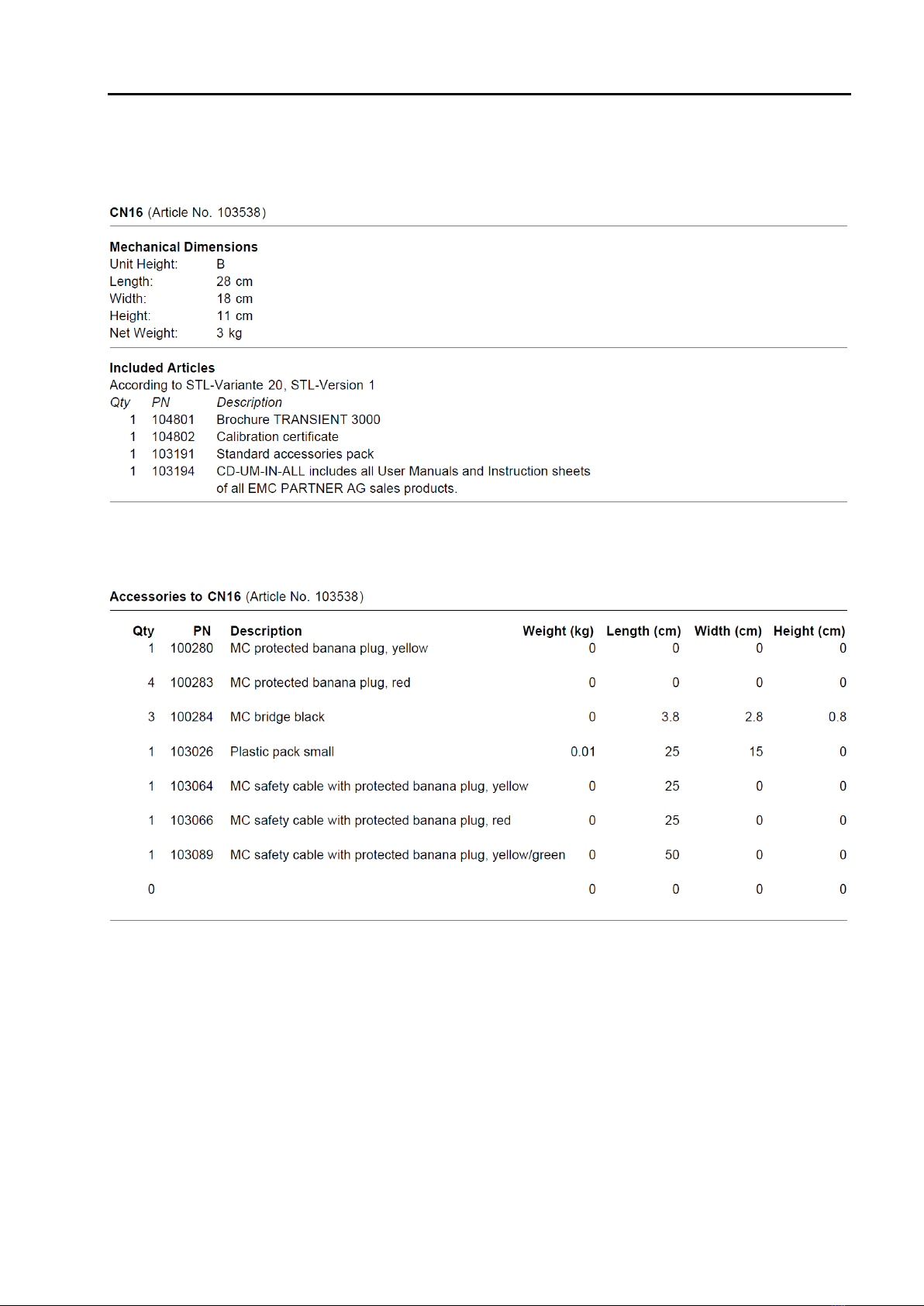
1.5 Accessories, dimensions 7
1.5.1 Included articles, dimensions 7
1.5.2 Standard accessories 7
2SAFETY 9
2.1 Safety standards 9
2.2 Climatic conditions 9
2.3 Precautionary measure during use 10
2.4 The manual is an integral part of the equipment. Refer to the manual. 10
3CONNECTING CN16 TO NW16S 11
3.1 General 11
4AC-VOLTAGE TEST 12
4.1 Coupling AC on one line 12
4.2 Coupling AC on two lines 13
4.3 Coupling AC on four lines 14
5DC-VOLTAGE TEST 15
5.1 Coupling DC on one line 15
5.2 Coupling DC on two lines 16
5.3 Coupling DC on four lines 17
61 HZ TO 150 KHZ TESTS 18
6.1 Coupling DC on two lines 18
6.2 Coupling on shielded lines 19
7RECYCLING / DISPOSAL 21
7.1 RoHS directive 2002/95/EG 21
7.2 WEEE directive 2002/96/EG 21
7.3 Information for dismantling 21
7.4 Parts which can be recycled 21
7.5 Parts which can not be recycled 21

Common Mode Coupling Network CN16
3/28
8SERVICE INFORMATION 23
9GLOSSARY 25


E-CN16-E-Manual 5/28
1 IEC 61000-4-16 Information
1.1 Schematic circuit for the type tests
1.2 Test levels

Common mode coupling network CN16
6/28
1.3 Additional Networks or Accessories
PN
Type
Short discription
PN
Type
Short discription
104123
EXT-TRA3000 C-
SHORT
Extends TRA3000 C with short test. EXT-TRA3000 C-SHORT
Consists of one external trafo box. Requires 1x PS3 power supply, 1x
RS485-RS232 ADAPTER to control the PS3 from TRA3000. Minimum
configuration TRA3000 C. IEC 61000-4-16
106900
CN16DC
Coupling network for common mode coupling dc up to 300V onto
EUTpower line voltage Lto N/PE of 230V according to IEC 61000-4-16.
The mains must be decoupled with a insulation transformer DN16-1P6
single phase 6A or DN16-1P16 single phase 16A
103539
CN16T
T-coupling network for telecom lines coupling dc, 50/60Hz and
sinusoidal up to 150kHz according to IEC 61000-4-16. application: 2
lines one pair
106962
DN16-1P16
Mains decoupling transformer single phase 230V/16A 50/60Hz. For
tests according to IEC 61000-4-16: DC, 50/60Hz and sinusoidal up to
150kHz . Housing 19" 4 UH For coupling select CN16, CN16T or
CN16DC
106961
DN16-1P6
Mains decoupling transformer single phase 230V/6A 50/60Hz. For
tests according to IEC 61000-4-16: DC, 50/60Hz and sinusoidal up to
150kHz. Housing 19" 4 UHdc. For coupling select CN16, CN16T or
CN16DC
105840
CN16-22-7C
Coupling network for common mode coupling up to 300V 50/60Hz in
accordance with IEC 60255-22-7, 2 ports: 2 x R 220 Ohm and 2 x C=
0.47µF
105841
CN16-22-7D
Coupling network for differential mode coupling up to 250V 50/60Hz in
accordance with IEC 60255-22-7, 2 ports: 2 x R 100 Ohm and 2 x C=
0.1µF
Common Mode Coupling Network CN16
7/28
1.4 Accessories, dimensions
1.4.1 Included articles, dimensions
1.4.2 Standard accessories

Common mode coupling network CN16
8/28

E-CN16-E-Manual 9/28
2 Safety
The CN16 belongs to safety class 1
2.1 Safety standards
The CN16 fulfils the requirements of the safety standards IEC 61010 „Safety requirements for electrical
equipment for measurement, control and laboratory use and the safety standard VDE 0104 ( Safety circuits,
warning lamps or connector for warning lamps ). Based on EN 61010 (IEC 61010) the declaration of
conformity to low voltage directive LVD 73/23/EEC (O.J. N° L77, 1973-03-26) is given.
This manual is a integral part of the CN16 network. The instructions contained in the manual
regarding operation and the test set up are to be strictly observed.
2.2 Climatic conditions
The CN16 generators contain high voltage circuits in integrated form. EMC PARTNER only guarantees a
correct functioning of the CN16 network and the associated accessories, if the CN16 is operated in the
climatic condition specified.
Temperature
15 °C to 35 °C
60 to 90°F
Relative humidity
45 % to 75 %
12.9 to 15.4 PSI
Atmospheric pressure
86 kPa to 106 kPa
(860 to 1060 mbar)
Not influenced by:
direct solar radiation, rain or condensate water, dust or larger electro
magnetic fields as specified in the EMC compatibility chapter.
The CN16 should be operated in a dry, clean room. If for any reason water condenses in the CN16, then no
CN16 operation should be started before the tester is dry.
It is strictly forbidden to operate the CN16 network in rooms with of gas explosion risk. The high
voltage of the CN16 can generate sparks, which can ignite the gas.
People with heart pacemakers should not be in the vicinity of the test set up during operation.
Common mode coupling network CN16
10/28
2.3 Precautionary measure during use
It is wise to observe the following rules:
Never touch the EUT when a test is in operation.
Touch no connectors of connection cable when a EMC test is in operation.
The high voltage of the CN16 network and the power on the EUT must turned off before a
manipulation on the EUT is carried out.
For all services, e.g. check of the fuses, the power cord must first be unplugged.
2.4 The manual is an integral part of the equipment. Refer to the manual.
This manual is an integral part of the CN16 network. The safety rules and precautions in the manual
must be observed. EMC PARTNER and their representatives are not responsible for damage to
persons and equipment by not observing the safety rules and precautions specified in this manual..

E-CN16-E-Manual 11/28
3 Connecting CN16 toTRA3000
3.1 General
Use the three cables (red, yellow and yellow/green) supplied to connect the CN16 to the TRA3000 C
For common mode tests connect the CN16’s ‘AC-L’ and ‘AC-N’ to the TRA3000 C ‘EUT Power L and ‘EUT
Power-N’ (as shown on the following picture for example).
The metallic box of the CN16 must be connected to the PE of the TRA3000
Caution
To avoid any damage of the EUT during CM test set-up the EUT power cord on the rear side of the
TRA3000 shall be removed. When the CM test is selected the power line is disconnected and the PWR1
and PWR2 can not switched “ON”. As soon as an other test e.g. Surge is selected the PWR1 and PWR2
can be activated and the power voltage is on L at the front of the TRA3000.

Common mode coupling network CN16
12/28
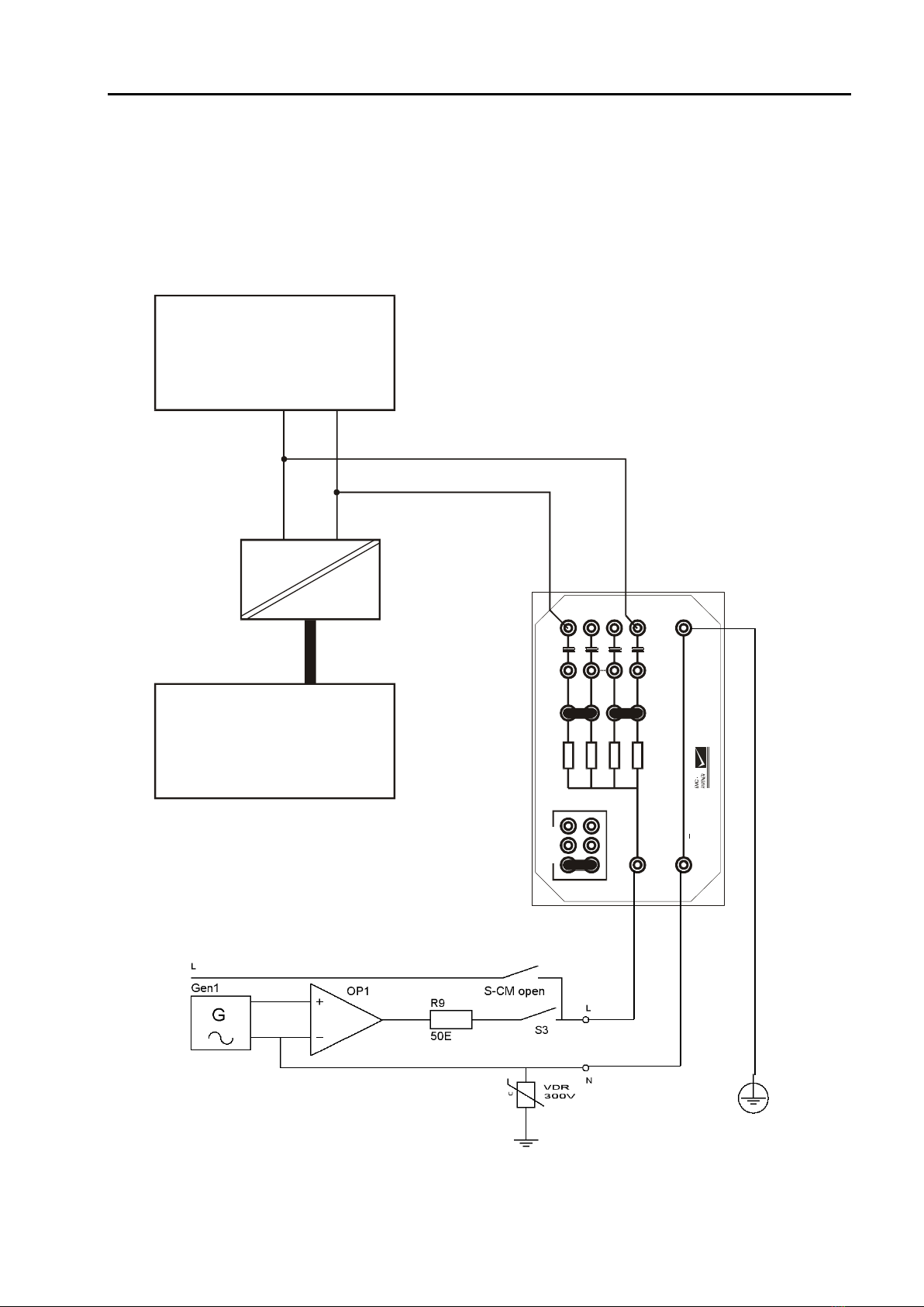
4 AC Test-Voltage
4.1 AC test generator; coupling on one line
Connect the cables and bridges as shown on the following picture:
400 R
400 R
400 R
400 R
1 uF
1 uF
1 uF
1 uF
EUT
AC-L
AC-N
Common
DC +
DC
CN-16
PARKING
AE EUT
Auxiliary
Equipment
Decoupling
Device
Common Mode Coupling Network CN16
13/28
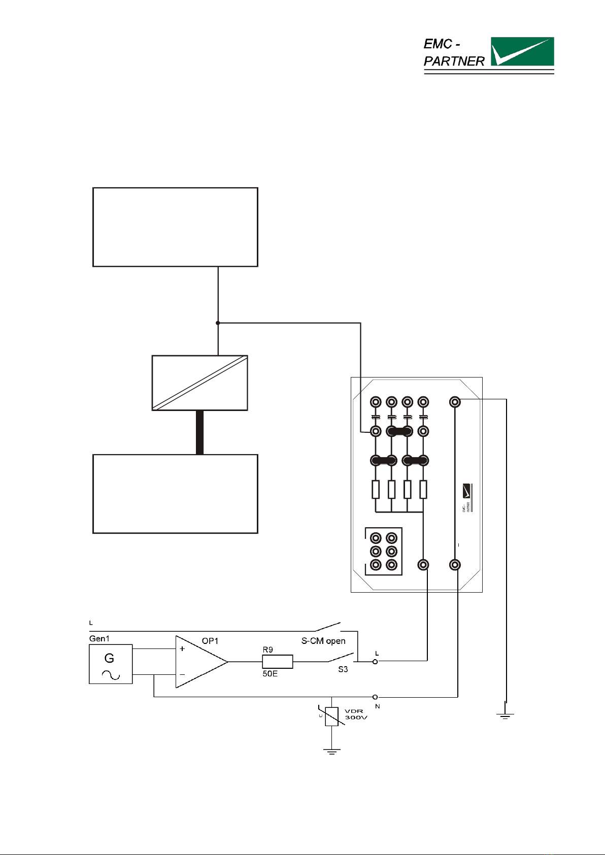
4.2 AC test generator; coupling on two lines
Maximum line to line voltage (EUT-AT) a.c. 230V and d.c.300V
Connect the cables and bridges as shown on the following picture:
400R
400R
400R
400R
1 uF
1 uF
1 uF
1 uF
EUT
AC-L
AC-N
Common
DC+
DC
CN-16
PARKING
AE EUT
Auxiliary
Equipment
Decoupling
Device

Common mode coupling network CN16
14/28
4.3 AC test generator; coupling on four lines
Maximum line to line voltage (EUT-AT) a.c. 230V and d.c.300V
Connect the cables and bridges as shown on the following picture:
400 R
400 R
400 R
400 R
1 uF
1 uF
1 uF
1 uF
EUT
AC-L
AC-N
Common
DC +
DC
CN-16
PARKING
AE EUT
Auxiliary
Equipment
Decoupling
Device
E-CN16-E-Manual 15/28
5 DC-Voltage Test
5.1 DC test generator; coupling on one line
Maximum line to line voltage (EUT-AT) a.c. ¨48V and d.c.68V
Connect the cables and bridges as shown on the following picture:
AE EUT
Auxiliary
Equipment
Decoupling
Device
400 R
400 R
400 R
400 R
1 uF
1 uF
1 uF
1 uF
EUT
AC-L
AC-N
Common
DC+
DC
CN-16
PARKING

Common mode coupling network CN16
16/28
5.2 DC test generator; coupling on two lines
Maximum line to line voltage (EUT-AT) a.c. ¨48V and d.c.68V
Connect the cables and bridges as shown on the following picture:
400 R
400 R
400 R
400 R
1 uF
1 uF
1 uF
1 uF
EUT
AC-L
AC-N
Common
DC +
DC
CN-16
PARKING
AE EUT
Auxiliary
Equipment
Decoupling
Device

Common Mode Coupling Network CN16
17/28
5.3 DC test generator; coupling on four lines
Maximum line to line voltage (EUT-AT) a.c. ¨48V and d.c.68V
Connect the cables and bridges as shown on the following picture:
400 R
400 R
400 R
400 R
1uF
1uF
1uF
1uF
EUT
AC-L
AC-N
Common
DC+
DC
CN-16
PARKING
AE EUT
Auxiliary
Equipment
Decoupling
Device

Common mode coupling network CN16
18/28
6 1 Hz to 150 kHz tests
6.1 Coupling on two lines
400R
400R
400R
400R
1 uF
1 uF
1 uF
1 uF
EUT
AC-L
AC-N
Common
DC+
DC
CN-16
PARKING
AE EUT
Auxiliary
Equipment
Decoupling
Device

Common Mode Coupling Network CN16
19/28
6.2 Coupling on shielded lines
AE EUT
Auxiliary
Equipment
Decoupling
Device
400 R
400 R
400 R
400 R
1uF
1uF
1uF
1uF
EUT
AC-L
AC-N
Common
DC+
DC
CN-16
PARKING

Common mode coupling network CN16
20/28
This manual suits for next models
1
Table of contents


