Norwegian Subsea MRU Subsea 3000 User manual

NORSUB
MRU Subsea User Manual
MRU Subsea User Manual Version 1.3.5
©2021 Norwegian Subsea AS
Document number: NORSUB-MSUM-1.3.5
English

.
Intro
The purpose of the user manual is to provide information about the Norwegian Subsea
(NORSUB) Subsea Motion Reference Units (MRU Subsea 3000, MRU Subsea 6000, and MRU
Subsea 9000 models).
III
Restrictions in Warranty
The Seller’s liability for defects is stated in the Norwegian Subsea general terms and
conditions of sale. For the warranty to be valid the MRU:
Support Information
Please contact Norwegian Subsea for technical support at support@norwegian-subsea.no.
Technical support is available Monday - Friday between 09.00 – 17.00 CET.
Product Returns
In case of product returns, the buyer shall arrange for return shipment to Norwegian
Subsea. Please note that a return merchandise authorization (RMA) from Norwegian
Subsea is required in advance.
The return address is: Norwegian Subsea
Hovfaret 8
0275 Oslo
Norway
Export Restrictions
The MRU must not be exported or re-exported to countries listed on the Norwegian
Ministry of Foreign Affairs’ prohibition list. Please contact Norwegian Subsea for further
details.
must not be subjected to extreme shock, rough handling or extensive vibrations.
must only be opened by Norwegian Subsea.
must not be stored or used in temperatures outside the range -40 to +85 deg. C.
must be handled with care.
must only be used with the correct power supply (10 – 36 V DC power).
Disposal
All electrical and electronic components have to be disposed
of separately from the municipal waste stream via designated
collection facilities appointed by the government or local
authorities. The correct disposal and separate collection of your old
appliance will help prevent potential negative consequences for
the environment and human health. It is a precondition for reuse
and recycling of used electrical and electronic equipment. For
more detailed information about disposal of your old appliance,
please contact your local authorities or waste disposal service.
In support of the global requirements to dispose of electrical waste within environmentally
acceptable specifications, Norwegian Subsea offers customers the take-back and recycle
process to properly dispose of surplus and end-of-life products.
Equipment that is returned to Norwegian Subsea through this program is disposed of in
an environmentally safe manner using processes that comply with the WEEE (EU Directive
on Waste Electrical and Electronic Equipment) regulations. All Norwegian Subsea-branded
products are accepted under the program.
Any breach of the points above will void the warranty.
IV V
NOTE
Please read this user manual to ensure proper use of the MRU and the
configuration software.
MRU SUBSEA USER MANUAL (NORSUB-MSUM-x.x.x)
REVISION HYSTORY
VERSION CODE NOTES
LEGACY
1.2.0 NORSUB-MSUM-1.2.0 First digital release.
1.3.0 NORSUB-MSUM-1.3.0
First print release. The manual is completely redesigned to
add all the important mechanical, electrical, and technical
sensor information.
1.3.1 NORSUB-MSUM-1.3.1 Minor correction of typos.
CURRENT 1.3.5 NORSUB-MSUM-1.3.5 Modified section “Restrictions in warranty”.
Added “Maintenance” section.
.
Disclaimer
© 2014 – 2021, Norwegian Subsea AS. All rights reserved. Information in this document is
subject to change without notice. Copy or redistribution of this document is forbidden
without authorization of Norwegian Subsea AS.

NORSUB MRU SUBSEA
An MRU for your needs
A high-end magnetometer can be included in the MRU to provide accurate magnetic head-
ing. The MRU Subsea comes in three different versions: 3000, 6000 and 9000 models to
accommodate for different accuracy requirements and budgets.
High performance 6 DoF motion sensor
NORSUB Motion Reference Units (MRU) are high performance,
compact and affordable. NORSUB MRUs use state-of-the-art
MEMS technology and advanced sensor fusion algorithms. This
results in accurate and reliable roll, pitch, yaw, surge, sway and
heave position and velocity measurements. The performance is
great also during horizontal accelerations and coupled motions.
Tailormade for subsea use
NORSUB MRU SUBSEA is ideal for use in subsea
applications such as riser motion monitoring,
ROV/AUV or subsea surveys. The MRU Subsea
is a very compact motion sensor that is depth
rated to 6000 m. The small size and foot-
print make it easy to install almost anywhere.
The high performance in irregular motions
makes it ideal for use in real sea conditions.
Easy interfacing
The NORSUB MRU SUBSEA comes in a water-
proof titanium housing with ethernet and seri-
al ports.Software upgrades are free of charge.
A wide range of industry standard and custom
protocols are included for easy interfacing to other
systems. The MRU can be delivered with custom
length cables and desired connector at your end.
NORSUB MRU SUBSEA
General information
The NORSUB MRU Subsea outputs roll, pitch, yaw, heave, surge
and sway measurements at configurable output rates up to 100 Hz.
The MRU Subsea consists of a high-end MEMS 6 DOF IMU (3 x gyroscopes and 3 x
accelerometers) and a processing unit where the motions states are calculated using an
advanced sensor fusion algorithm. The MRU Subsea comes with a 8 pin SubConn connector.
This manual describes the mechanical and electrical interfaces needed to integrate
the MRU Subsea in a system, and the technical specifications of all the available models.
VI VII
A solution for every application
Norwegian Subsea AS offers a portfolio of sensors, cables, connectors, and software tools
which covers a variety of applications, environmental, and operational requirements.
Visit the company website to choose the Norwegian MRU Subsea that fits your needs!
TABLES
CONTENTS
FIGURES
1. GENERAL INFORMATION 1
Quick Start Guide 2
MRU Subsea Models 3
Product List 4
Items List 6
System Set-Up 7
2. MECHANICAL INTERFACE 9
Design 10
Technical Drawings 12
3. ELECTRICAL INTERFACE 15
Subsea Cable / Connectors 16
Subsea Cable 18
4. TECHNICAL SPECIFICATIONS 21
Output Protocols 22
Output Variables 24
Technical Specifications 26
5. MAINTENANCE 29
Maintenance General Information 30
Firmware Upgrades 30
Re-calibration 30
Repairs 31
Troubleshooting 31
1. GENERAL INFORMATION 1
Figure 1: System set-up for the MRU Subsea /
MRU Subsea H, Ethernet connection. 7
2. MECHANICAL INTERFACE 9
Figure 2: MRU Subsea / MRU Subsea H:
front and bottom views. 10
Figure 3: MRU Subsea / MRU Subsea H:
isometric, and front views. 11
Figure 4: MRU Subsea / MRU Subsea H technical drawings:
top view. 12
Figure 5: MRU Subsea / MRU Subsea H technical drawings:
bottom view. 12
Figure 6: MRU Subsea / MRU Subsea H technical drawings:
side view. 13
3. ELECTRICAL INTERFACE 15
Figure 7: Subsea cable cross section and
SubConn connectors (female and male). 16
1. GENERAL INFORMATION 1
Table 1: Norwegian Subsea MRU
Subsea-related product list (part 1). 4
Table 2: Norwegian Subsea MRU
Subsea-related product list (part 2). 5
3. ELECTRICAL INTERFACE 15
Table 3: Subsea cable and connector
configurations 1 and 2. 16
Table 4: Subsea cable and connector
configurations 3,4, and 5. 17
Table 6: Subsea cable components descriptions. 18
Table 7: Subsea cable technical details. 18
Table 5: Subsea cable electrical characteristics. 18
4. TECHNICAL SPECIFICATIONS 21
Table 8: List of output protocols. 22
Table 9: Output protocol variables (part 1). 24
Table 10: Output protocol variables (part 2). 25
Table 11: MRU Subsea physical characteristics. 26
Table 12: MRU Subsea performance. 26
Table 13: MRU Subsea range. 26
Table 15: MRU Subsea power and interfaces. 27
Table 14: MRU Subsea environmental specification. 27
5. MAINTENANCE 29
Table 16: MRU performance and re-calibration. 31
VIII IX

.
1. GENERAL INFORMATION

MRU Subsea Models
GENERAL INFORMATIONGENERAL INFORMATION
2 3
The MRU Subsea comes in 6 different models which cover a variety of performance levels
and features. The MRU Subsea models are:
MRU Subsea 9000 H
Sensor class
Sensor type
Sensor model: 3000 (lower specs), 6000
(medium specs), 9000 (higher specs)
“Heading”: the MRU includes
a magnetometer for heading
measurement
Variations between models will be explicitly described in this manual.
In the following the MRU Subsea 3000/6000/9000 will be referred to as “Basic”, the MRU
Subsea 3000/6000/9000 H will be referred to as “H”.
MRU Subsea 3000
MRU Subsea 6000
MRU Subsea 9000
MRU Subsea 3000 H
MRU Subsea 6000 H
MRU Subsea 9000 H
The model name is explained here:
{
{
BASIC
H
Verify that all the items are in the shipment (see
MRU Subsea User Manual for details).
1. CHECK ITEMS
Connect the MRU Subsea to a PC through an
Ethernet port with or to a system with the SubConn
connector (see MRU Subsea User Manual for
details).
Install the configured MRU Subsea at the desired
location.
Install the NORSUB MRU Configuration Software
by double clicking on the installer file (setup.exe)
on the USB memory stick (see MRU Configuration
Software User Manual for details).
Run the NORSUB MRU Configuration Software to
configure the MRU Subsea (see MRU Configuration
Software User Manual for details).
3. INSTALL THE SOFTWARE
2. CONNECT THE MRU
4. CONFIGURE THE MRU
5. INSTALL THE MRU
Quick Start Guide
.
NORWEGIAN MRU Subsea SUBSEA-RELATED PRODUCT LIST
PRODUCT NAME PRODUCT CODE
NORSUB MRU 9000 Subsea 10013
MRU SUBSEA
NORSUB MRU 6000 Subsea 10014
NORSUB MRU 3000 Subsea 10015
NORSUB MRU 9000 Subsea H 10016
NORSUB MRU 6000 Subsea H 10017
NORSUB MRU 3000 Subsea H 10018
NORSUB MRU 9000 Subsea (Ethernet & RS-232) 10101
NORSUB MRU 6000 Subsea (Ethernet & RS-232) 10102
NORSUB MRU 3000 Subsea (Ethernet & RS-232) 10103
NORSUB MRU 9000 Subsea H (Ethernet & RS-232) 10104
NORSUB MRU 6000 Subsea H (Ethernet & RS-232) 10105
NORSUB MRU 3000 Subsea H (Ethernet & RS-232) 10106
NORSUB MRU 9000 Subsea (RS-232 & RS-485) 10113
NORSUB MRU 6000 Subsea (RS-232 & RS-485) 10114
NORSUB MRU 3000 Subsea (RS-232 & RS-485) 10115
NORSUB MRU 9000 Subsea H (RS-232 & RS-485) 10116
NORSUB MRU 6000 Subsea H (RS-232 & RS-485) 10117
NORSUB MRU 3000 Subsea H (RS-232 & RS-485) 10118
NORSUB MRU 9000 Subsea (Ethernet & 2 wire RS-485) 10125
NORSUB MRU 6000 Subsea (Ethernet & 2 wire RS-485) 10126
NORSUB MRU 3000 Subsea (Ethernet & 2 wire RS-485) 10127
NORSUB MRU 9000 Subsea H (Ethernet & 2 wire RS-485) 10128
NORSUB MRU 6000 Subsea H (Ethernet & 2 wire RS-485) 10129
NORSUB MRU 3000 Subsea H (Ethernet & 2 wire RS-485) 10130
Product List
GENERAL INFORMATIONGENERAL INFORMATION
4 5
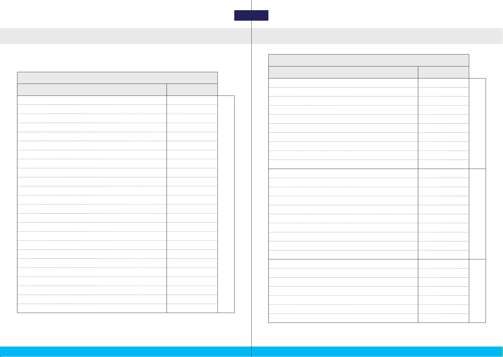
Product List
The MRU Subsea, subsea cables, and other accessories that are available for purchase at
Norwegian Subsea are listed in the following: NORWEGIAN MRU Subsea SUBSEA-RELATED PRODUCT LIST
PRODUCT NAME PRODUCT CODE
Subsea SW Cable 2 m 30011
SUBSEA CABLES
Subsea SW Cable 5 m 30012
Subsea SW Cable 10 m 30013
Subsea SW Cable 20 m 30014
Subsea SW Cable xx m 30015
Subsea Cable 2 m 30021
Subsea Cable 5 m 30022
Subsea Cable 10 m 30023
Subsea Cable 20 m 30024
Subsea Cable xx m 30025
Subsea Pigtail SW Cable 2 m 30016
SUBSEA PIGTAILS
Subsea Pigtail SW Cable 5 m 30017
Subsea Pigtail SW Cable 10 m 30018
Subsea Pigtail SW Cable 20 m 30019
Subsea Pigtail SW Cable xx m 30020
Subsea Pigtail Cable 2 m 30026
Subsea Pigtail Cable 5 m 30027
Subsea Pigtail Cable 10 m 30028
Subsea Pigtail Cable 20 m 30029
Subsea Pigtail Cable xx m 30030
Subsea SW Test Cable 10 m 30031
ACCESSORIES
Subsea Custom Cable 30032
Transport Case M 40001
Power Supply 24 V DC 40002
Subsea Dummy Plug F 40003
Subsea Dummy Plug M 40004
USB stick with MRU configuration software 40005
Table 1: Norwegian Subsea MRU Subsea-related product list (part 1).
Table 2: Norwegian Subsea MRU Subsea-related product list (part 2).

GENERAL INFORMATION
Items List
GENERAL INFORMATION
6 7
NORSUB MRU Subsea Subsea cable, 10m
A standard shipment of the MRU Subsea 3000 / MRU Subsea 3000 H, MRU Subsea 6000 /
MRU Subsea 6000 H, MRU Subsea 9000 / MRU Subsea 9000 H contains the following items
(*):
1. MRU
6. USER MANUALS
2. CABLE
5. USB FLASH DRIVE
Configuration Software user
manual and MRU Subsea
user manual
USB drive with the NORSUB
MRU Configuration
Software
1. 1 x NORSUB MRU Subsea;
2. 1 x Subsea cable (10 m);
3. 1 x Power supply;
4. 1 x USB flash drive containing the NORSUB MRU Configuration Software;
5. 1 x Configuration Software user manual and 1 x MRU Subsea user manual.
(*) The shipment content (such as cable length and cable connectors) may vary from the
above item list depending on items in your order (see “Product List” on page 4).
System Set-Up
GENERAL INFORMATION
Connect the male connector of the subsea cable to the MRU SubConn connector, and
the other end to your system (*). In the following figure, a subsea cable with an RJ45
plug and a power barrel jack is shown.
Connect the RJ45 plug (ethernet) or DB-9 connector (serial) to your system.
Connect the power cable to the power supply. It is recommended to plug the power
supply to the power socket last, because this operation will start-up the MRU Subsea.
Figure 1: System set-up for the MRU Subsea / MRU Subsea H, Ethernet connection.
Host PC
Subsea cable
MRU Subsea / MRU Subsea H
Power supply
Power socket
MRU Config. Software

2. MECHANICAL INTERFACE
.
Design
MECHANICAL INTERFACE
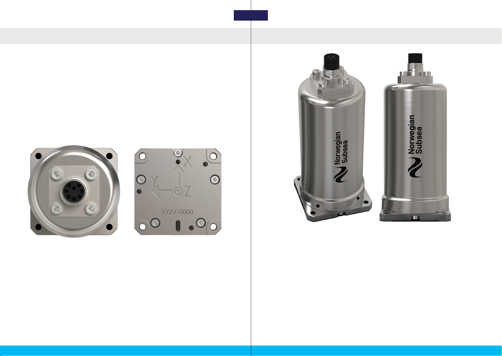
Figure 3: MRU Subsea / MRU Subsea H: isometric, and front views.
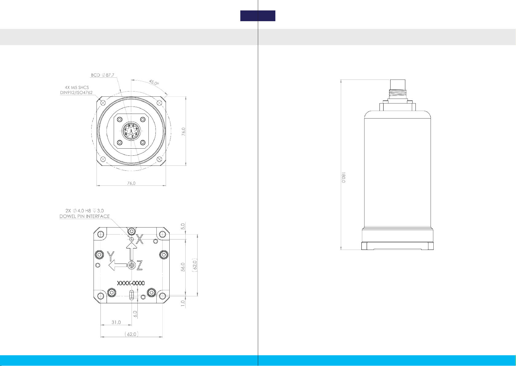
The dimensions of the MRU Subsea / MRU Subsea H are:
Length: 76 mm;
Breadth: 76 mm;
Height: 180 mm.
The footprint of the MRU Subsea is seen in Figure 5, dimensions are in millimeters. This
shows the 4 mounting holes and the 2 alignment holes / slots on the center line. The MRU
is mounted to a solid surface using 4 x M5 screws. 4 mm diameter alignment dowels are
recommended for best alignment during installation.
The MRU Subsea 3000, MRU Subsea 3000 H, MRU Subsea 6000, MRU Subsea 6000 H,
MRU Subsea 9000, and MRU Subsea 9000 H are identical when considering geometry,
construction and materials.
Design
MECHANICAL INTERFACE
10 11
Figure 2: MRU Subsea / MRU Subsea H: front and bottom views.
Technical Drawings
MECHANICAL INTERFACE
Figure 6: MRU Subsea / MRU Subsea H technical drawings: side view.
12 13
Technical Drawings
MECHANICAL INTERFACE
Figure 4: MRU Subsea / MRU Subsea H technical drawings: top view.
MRU Subsea / MRU Subsea H top and bottom technical drawings. All dimensions are in
millimeters:
Figure 5: MRU Subsea / MRU Subsea H technical drawings: bottom view.
MRU Subsea / MRU Subsea H side technical drawing. All dimensions are in millimeters:

3. ELECTRICAL INTERFACE
.

ELECTRICAL INTERFACE
Subsea Cable / Connectors
ELECTRICAL INTERFACE
16 17
Subsea Cable / Connectors
The MRU Subsea and MRU Subsea H models are connected to a system with the subsea
cable plugged to a SubConn connector. The 8 pin SubConn connector has not enough pins
for power, Ethernet, RS-232 and RS-485 ports. The 5 available power and communication
configurations for the SubConn connector are given below. Note that all signals are w.r.t to
the MRU connector.
Figure 7: Subsea cable cross section and SubConn connectors (female and male).
18
7
6
5
4
3
212
3
4
5
6
7
8
SUBSEA CABLE
AND SUBCONN CONNECTOR
CONFIGURATION 1
WIRE COLOR PIN N. SIGNAL
TP 4 (Brown) 1 GND
POWER
TP 4 (White /Brown) 224V
TP 1 (Blue) 3 GND
TP 1 (White/Blue) 424V
TP 2 (White/Orange) 5Tx_D1+
ETHERNET
TP 2 (Orange) 6Tx_D1-
TP 3 (White/Green) 7Rx_D2+
TP 3 (Green) 8Rx_D2-
SUBSEA CABLE
AND SUBCONN CONNECTOR
CONFIGURATION 2
WIRE COLOR PIN N. SIGNAL
TP 4 (Brown) 1 GND
POW.
TP 4 (White /Brown) 224V
TP 1 (Blue) 3Tx
RS-232
TP 1 (White/Blue) 4 Rx
TP 2 (White/Orange) 5Tx_D1+
ETHERNET
TP 2 (Orange) 6Tx_D1-
TP 3 (White/Green) 7Rx_D2+
TP 3 (Green) 8Rx_D2-
SUBSEA CABLE
AND SUBCONN CONNECTOR
CONFIGURATION 3
WIRE COLOR PIN N. SIGNAL
TP 4 (Brown) 1 GND
POW.
TP 4 (White /Brown) 224V
TP 1 (Blue) 3Tx
RS-232
TP 1 (White/Blue) 4 Rx
TP 2 (White/Orange) 5Tx+
RS-485
TP 2 (Orange) 6Tx-
TP 3 (White/Green) 7Rx+
TP 3 (Green) 8Rx-
SUBSEA CABLE
AND SUBCONN CONNECTOR
CONFIGURATION 4
WIRE COLOR PIN N. SIGNAL
TP 4 (Brown) 1 GND
POWER
TP 4 (White /Brown) 224V
TP 1 (Blue) 3 GND
TP 1 (White/Blue) 424V
TP 2 (White/Orange) 5Tx+
RS-485
TP 2 (Orange) 6Tx-
TP 3 (White/Green) 7Rx+
TP 3 (Green) 8Rx-
Table 3: Subsea cable and connector configurations 1 and 2.
SUBSEA CABLE
AND SUBCONN CONNECTOR
CONFIGURATION 5
WIRE COLOR PIN N. SIGNAL
TP 4 (Brown) 1 GND
POW.
TP 4 (White /Brown) 224V
TP 1 (Blue) 3 (B)+
RS-485
TP 1 (White/Blue) 4 (A)-
TP 2 (White/Orange) 5Tx_D1+
ETHERNET
TP 2 (Orange) 6Tx_D1-
TP 3 (White/Green) 7Rx_D2+
TP 3 (Green) 8Rx_D2-
Table 4: Subsea cable and connector configurations 3,4, and 5.
Subsea Cable
ELECTRICAL INTERFACE
18
SUBSEA CABLE ELECTRICAL CHARACTERISTICS
PARAMETER VALUE
Depth rating 250V max. 1 amp
Conductor resistance ≤ 85 ohm/km (26 ohm/1,000-FT)
Capacitance 42 pF/m to for 55 pF/m (13 pF/FT to for 17 pF/FT)
Impedance 85 ohm to 125 ohm
Table 5: Subsea cable electrical characteristics.
SUBSEA CABLE COMPONENTS
ITEM DESCRIPTION
Power conductor
0.20 mm (24 AWG) two silver-plated copper conductors insulated
with teflon and twisted together (4 ea.). Each pair has a different
twist-rate for crosstalk performance and each pair has a TPE belt-to
round jacket for performance at pressure
Shield Aluminium/polyester tape and tinned copper braiding (85% cover-
age) with an overall polyester tape
Filler The cable is filled with cable filling compound
Outer jacket Polyurethane jacket. Colour blue
Color code
1. TP = White/Blue + Blue
2. TP = White/Orange + Orange
3. TP = White/Green + Green
4. TP = White/Brown + Brown
SUBSEA CABLE TECHNICAL DETAILS
PARAMETER VALUE
Diameter 10,4 mm nom. (0,410 ± 0,010 inch)
Weight in air 140 kg/km nom. (95 lbs/1,000 feet nom.)
Weight in seawater 53 kg/km nom. (36 lbs/1,000 feet nom.)
Minimum bending radius 100 mm (4 inch)
Depth rating 6000 metres (8700 psi)
Table 6: Subsea cable components descriptions.
Table 7: Subsea cable technical details.

4. TECHNICAL SPECIFICATIONS
.
Output Protocols
TECHNICAL SPECIFICATIONS
Output Protocols
TECHNICAL SPECIFICATIONS
Table 8: List of output protocols.
22 23
Custom NMEA: custom output protocol in NMEA format. See the MRU Configuration
Software User Manual for the full list of available output variables.
Custom Binary: custom output protocol in binary format. See the MRU Configuration
Software User Manual for the full list of available output variables.
NAME TYPE DATA
Custom NMEA NMEA See next page
Custom Binary Binary See next page
ATLAS Binary Roll, pitch, heave
GYROCOMPAS1 NMEA Roll, pitch, heading, status
IFREMER VICTOR Binary Roll, pitch, heading, roll rate, pitch rate, yaw rate, acc x, acc y, acc z
MDL ASCII Roll, pitch, heading
NORSUB NMEA Roll, pitch, yaw, heave
NORSUB2 NMEA Roll, pitch, yaw, heave, heave vel
NORSUB6 NMEA Roll, pitch, yaw, surge, sway, heave, roll rate, pitch rate, yaw rate, surge
vel, sway vel, heave vel, acc x, acc y, acc z
NORSUB7 NMEA
Roll, pitch, yaw, surge (body frame), sway (body frame), heave, roll rate,
pitch rate, yaw rate, surge vel (body frame), sway vel (body frame),
heave vel, acc x (body frame), acc y (body frame) acc z, period x, period
y, period z, amplitude x, amplitude y, amplitude z, STATUS
NORSUB7b NMEA
Roll, pitch, yaw, surge (body frame), sway (body frame), heave, roll rate,
pitch rate, yaw rate, surge vel (body frame), sway vel (body frame),
heave vel, acc x (body frame), acc y (body frame) acc z, period x, period
y, period z, amplitude x, amplitude y, amplitude z, STATUS_A, STATUS_B
NORSUB8 NMEA
Roll, pitch, yaw, surge (NED frame), sway (NED frame), heave, roll rate,
pitch rate, yaw rate, surge vel (NED frame), sway vel (NED frame), heave
vel, acc x (NED frame), acc y (NED frame), acc z, period x, period y, peri-
od z, amplitude x, amplitude y, amplitude z, STATUS
NORSUB PRDID NMEA Pitch, roll
Tokimek PTVG NMEA Roll, pitch, yaw
RDI ADCP NMEA Roll, pitch, yaw
SMCA NMEA Roll, pitch, surge, sway, heave
SMCC NMEA Roll, pitch, yaw, surge, sway, heave, surge vel, sway vel, heave vel, acc x,
acc y, acc z
Simrad EM 3000 Binary Roll, pitch, yaw, heave
TSS1 ASCII Roll, pitch, heave, status
The industry standard and custom NMEA/ASCII and binary protocols available on the MRU
are:

Output Variables
TECHNICAL SPECIFICATIONS
Output Variables
TECHNICAL SPECIFICATIONS
24 25
NAME
TYPE
DATA
Roll
Pitch
Yaw
Roll rate
Pitch rate
Yaw rate
Surge
Sway
Heave
Surge velocity
Sway velocity
Heave velocity
Surge acc.
Sway acc.
Heave acc.
Surge period
Sway period
Heave period
Surge amplitude
Sway amplitude
Heave amplitde
STATUS
STATUS_A
STATUS_B
NORSUB
PRDID
ASCII
Tokimek
PTVG
ASCII
RDI ADCP
ASCII
SMCA
ASCII
SMCC
ASCII
Simrad EM
3000
bin.
TSS1
bin.
Table 10: Output protocol variables (part 2).
The following table shows the available variables for every protocol.
NAME
TYPE
DATA
Roll
Pitch
Yaw
Roll rate
Pitch rate
Yaw rate
Surge
Sway
Heave
Surge velocity
Sway velocity
Heave velocity
Surge acc.
Sway acc.
Heave acc.
Surge period
Sway period
Heave period
Surge amplitude
Sway amplitude
Heave amplitde
STATUS
STATUS_A
STATUS_B
Atlas
bin.
Gyrocompas1
ASCII
Ifremer Victor
bin.
MDL
ASCII
NORSUB
ASCII
NORSUB2
ASCII
NORSUB6
ASCII
NORSUB7
ASCII
NORSUB7b
ASCII
NORSUB8
ASCII
Table 9: Output protocol variables (part 1).
Technical Specifications
TECHNICAL SPECIFICATIONS
27
MRU SUBSEA 3000/6000/9000 ENVIRONMENTAL SPECIFICATION
PARAMETER BASIC & H
Enclosure material Titanium grade 5
Enclosure protection 6000 m
Operating temperature range -20 to +70 degrees Celsius
Operating humidity (max) No limit (sealed)
Storage temperature range -40 to +80 degrees Celsius
Storage humidity No limit (sealed)
Electromagnetic compatibility (immu-
nity/emission) IEC 60945/EN 60945
Vibration IEC 60945/EN 60945
Max shock non-operational
(10 ms peak) 2000 m/s (half-sine 0.5 msec)
MTBF (computed) 100000 h
Table 11: MRU Subsea physical characteristics.
MRU SUBSEA RANGE
PARAMETER 3000 3000 H 6000 6000 H 9000 9000 H
Acceleration
range +/- 3 g +/- 3 g +/- 4 g +/- 4 g +/- 10 g +/- 10 g
Gyroscopes +/- 150
degs/s
+/- 150
degs/s
+/- 450
degs/s
+/- 450
degs/s
+/- 450
degs/s
+/- 450
degs/s
Heave +/- 50 m +/- 50 m +/- 50 m +/- 50 m +/- 50 m +/- 50 m
Yaw N/A 360 degs N/A 360 degs N/A 360 degs
Pitch +/- 90 degs +/- 90 degs +/- 90 degs +/- 90 degs +/- 90 degs +/- 90 degs
Roll +/- 180 degs +/- 180 degs +/- 180 degs +/- 180 degs +/- 180 degs +/- 180 degs
Output fre-
quency 0 - 100 Hz 0 - 100 Hz 0 - 100 Hz 0 - 100 Hz 0 - 100 Hz 0 - 100 Hz
Table 14: MRU Subsea environmental specification.
Technical Specifications
TECHNICAL SPECIFICATIONS
MRU SUBSEA PERFORMANCE
PARAMETER 3000 3000 H 6000 6000 H 9000 9000 H
Roll & pitch +/- 0.05 degs +/- 0.05 degs +/- 0.02 degs +/- 0.02 degs +/- 0.01 degs +/- 0.01 degs
Real-time
heave
5.0 cm or
5.0 %
5.0 cm or
5.0 %
5.0 cm or
5.0 %
5.0 cm or
5.0 %
5.0 cm or
5.0 %
5.0 cm or
5.0 %
Heading N/A +/- 0.5 degs N/A +/- 0.5 degs N/A +/- 0.5 degs
Table 12: MRU Subsea performance.
MRU SUBSEA 3000/6000/9000 POWER AND INTERFACES
PARAMETER BASIC & H
Power consumption 6.0 W
Supply voltage 10-36 V DC (24 V nominal)
Internal storage 32 GB
Communication
One of the following:
Ethernet
Ethernet and RS-232
RS-232 and RS-485
RS-485
Ethernet and 2 wire RS-485
Protocols See “Output Protocols” on page 22
for the complete list
Table 13: MRU Subsea range.
MRU SUBSEA 3000/6000/9000 PHYSICAL CHARACTERISTICS
PARAMETER BASIC & H
Weight 1600 g
L x B x H 760 x 760 x 180 mm
Depth rating 6000 m
Table 15: MRU Subsea power and interfaces.
26 27

.
5. MAINTENANCE
This manual suits for next models
5
Table of contents
Other Norwegian Subsea Marine Equipment manuals

Popular Marine Equipment manuals by other brands


Dometic GROUP
Dometic GROUP SeaLand VacuFlush HTS-VG owner's manual

Nasaco
Nasaco YACHT REPEATER Installation and user instructions

New Age
New Age PRM 601 Workshop manual

Edgetech
Edgetech Model 3100P Sub-bottom Sonar System Hardware manual

Abus
Abus FUSG50110 quick guide

Edgetech
Edgetech STARMUX IV USER HARDWARE MANUAL


