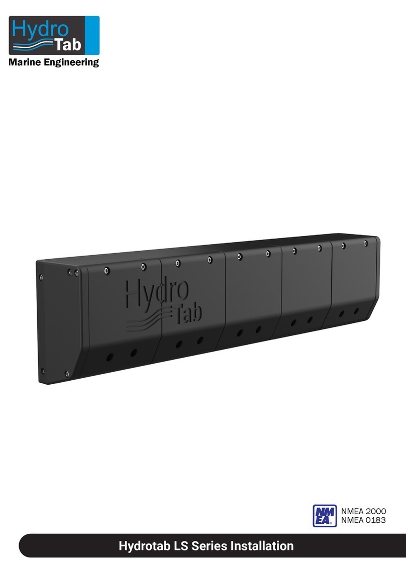
hydrotab BT Series User manual

Hydro
Tab
Marine Engineering
Hydrotab BT Series
Hydrotab BT installation & Moby Automatic controller
NMEA 2000
NMEA 0183
Hydro
Tab
Marine Engineering

2
Hydro
Tab
Marine Engineering
Disclaimer
The interceptor units are also steering
equipment and it is the sole responsibility of
the navigator-operator to ensure that, at any
point, any problem that will alter the boat's
course, rising from malfunction of
interceptors, should be dealt immediately by
the operator. At no circumstances, fault of our
interceptor equipment leading to any kind of
accident, creates liability for the
manufacturer.
Trademark Notice
Hydrotab is a registered trademark of Olympic
Engineering Ltd, Greece. All other trademarks,
trade names or company names referenced
herein are used for identification only and are
property of their respective owners.
Patent Notice
The Hydrotab products are protected by
patents and industrial design patents, patents
pending or design patents pending.
Declaration of conformity
This product conforms to the following
Electromagnetic Compatibility (EMC)
regulations and standards for use in marine
environments.
CE EN 60945
Technical information and
Documentation
The technical information provided in this
document was accurate and correct at the
corresponding production time of the
Hydrotab interceptors. Our operating principal
for improving the manufactured product, may
lead to changes regarding its specifications
without prior notice. Liability will not be
accepted for any inaccuracy considering the
product and the user manual.
Fair use statement
This manual can be printed or copied for your
own use only. Copies should not be provided
to third parties and manual should not be
commercialized.
Product Disposal
Waste removal of this product must be
according to the Waste Electrical and
Electronic Equipment (WEEE) Directive.
Product Registration
Please register your product online in order
the warranty to be valid.

3
Hydro
Tab
Marine Engineering
Table of Contents
Disclaimer
2
Installation Kit
4
Required Tools for Installation
5
Before Installation
5
Safety precautions
5
Proper Interceptor Installation in Transom
6
Interceptor Installation
7
BT Series Interceptor and Anode Mounting and Coating Instructions
13
Interceptor Installation (Indirect Air Supply)
14
Air Unit Installation
14
Air Unit Fuse Replacement
15
Moby Controller Installation
16
Air Unit: Direct Installation Diagram
17
Air Unit: Installation diagram on existing NMEA Network
17
Double Speed Air Unit: Direct Installation Diagram
18
Double Speed Air Unit: Installation diagram on existing NMEA Network
18
Single Air Unit Electrical Diagram
19
Single Air Unit Pneumatic Diagram
19
Double Speed Air Unit Electrical Diagram
20
Double Speed Air Unit Pneumatic Diagram
20
Spare Parts List - Model: 160BT (ASM-00928)
21
Spare Parts List - Model: 320BT (ASM-00560)
22
Spare Parts List - Model: 480BT (ASM-00561)
23
Spare Parts List - Model: 640BT (ASM-00562)
24
Spare Parts List - Model: 800BT (ASM-00563)
25
Spare Parts List - Model: 960BT (ASM-00564)
26
Spare Parts List - Model: 1500BT (ASM-00940)
27
Spare Parts List - Model: 2000BT (ASM-00941)
28
Spare Parts List - Air Unit (ASM-01065)
29
Spare Parts List - Double Speed Air Unit (ASM-01174)
30
Moby Troubleshooting
31
Warranty Conditions
32

4
Hydro
Tab
Marine Engineering
Installation Kit
1. Two interceptors
6. Pipe 8mm
Use drill Ø5.5mm x 9 holes
Χρησιμοποιήστε τρυπάνι Ø5.5mm x 9 τρύπες
Lower edge of the hull
Άκρη γάστρας
Άνω
μέρος
Άνω
μέρος
MOD: 480BT
Use drill Ø8.5mm
Χρησιμοποιήστε τρυπάνι Ø8.5mm
Use drill Ø4mm
Χρησιμοποιήστε τρυπάνι Ø4mm
Use drill Ø4mm
Χρησιμοποιήστε τρυπάνι Ø4mm
Use drill Ø4mm
Χρησιμοποιήστε τρυπάνι Ø4mm
4. Cables
2. Two interceptor drilling patterns
8. Screws
Air Unit wall mounting screws (4,8x25)
Fitting mounting screws (4,8x25)
Interceptor mounting screws (6,3x32)
3m-supply cable - Female
+
-
3m Male-Female
10m Female-Female
Inline terminator
3m Male-Female
12V or 24V 24V only
5. Moby Controller
MenuAuto
7. Moby Controller Drilling Pattern
Use drill Ø10mm
Χρησιμοποιήστε
τρυπάνι Ø10mm
MOBY CONTROLLER DRILLING PATTERN
Cut here
Κόψτε εδώ
114 mm
88 mm
Άνω
μέρος
Use drill Ø10mm
Χρησιμοποιήστε
τρυπάνι Ø10mm
Use drill Ø10mm
Χρησιμοποιήστε
τρυπάνι Ø10mm
Use drill Ø10mm
Χρησιμοποιήστε
τρυπάνι Ø10mm
9. Fittings
Indirect air supply pipe holder mounting
screws (3,5x13)
3. One Hydrotab AIR unit 12 OR 24VDC

5
Hydro
Tab
Marine Engineering
A good hint is that the closer the units are to the water line, the best the bank control of the boat will be
(Figure 3).
Attention! Please make sure that the pipe
insertion hole is accessible from the engine room
(Figure 2).
Make sure there are no obstructions behind the
drilling area (tanks, fuel lines, cabling) which can
be damaged or prevent the installation (Figure 1).
1. For high speed boats, overtrim may cause unexpectable turn. Improper use of trim tabs, may result to
accident or injury.
2. DO NOT PLACE YOUR FINGERS INSIDE THE INTERCEPTOR, through the front holes (Figure 4).
Severe injury danger!!!
Before Installation
21
3Right
Wrong
Drill Ø4 Drill Ø8,5
Drill Ø5.5 Hole Saw Ø70
Drill Ø3
5mm
Allen Key No 5Screwdriver Drilling tool
Marking tool
(pencil or marker)
Sikaflex gun
Safety precautions
WARNING!
4
Required Tools for Installation
If there is a double installation on the boat please
allow a 18 to 20 mm space between them (Figure
4).

6
Hydro
Tab
Marine Engineering
Right
Transom
Interceptor
Proper interceptor installation in transom
For maximum performance and less drag, install interceptors on the transom so blades deploy vertically.
If transom is not vertical to water plane, correct the angle by using wedges or other means.
Transom
Interceptor
Wrong
If the boat's transom has a significant curvature, it is necessary to create a flat plane for the installation
(acceptable flatness tolerance: 2mm).
Optimal
Less performance Correct angle
More drag
wedge
For aluminum hulls, it is suggested Isolation Plates between hull and interceptors to be installed. You can
find installation instructions in the Isolation Plates Kit.

7
Hydro
Tab
Marine Engineering
Interceptor Installation
5
Tape
Remove the pattern and drill according
the pattern indications
Drill all the pattern holes with a 3mm bore
without removing the pattern
6
You will need
No 4 No 8,5
No 5,5

8
Hydro
Tab
Marine Engineering
Allen 5mm
Interceptor Installation
8
Use a spatula to clean the excessive
glue from the holes
9
7
Use the special pipe
included in the packaging
M6,3xL*
Optional: Connecting Interceptors with Earthing Grid of boat
Except periodical replacement of anodes, you can enhance protection of interceptors from electrolytic corrosion by connecting
them to the earthing grid of the boat:
1. Drill through the hull one of the mounting pattern-holes on the transom.
2. Replace one regular self-tapping mounting screw (M6,3x32), with a longer screw (Inox 316, Φ6.3mm) so to run through the
transom wall (use sealant before tightening the screw).
3. Connect the screw with earthing grid of boat.
*Use inox 316 screw M6.3 of appropriate length
to run through the transom (not included in the set)
Apply sealant Sikaflex 291 to the holes

9
Hydro
Tab
Marine Engineering
Interceptor Installation
10
11
Direct air supply Optional:
Indirect Air Supply Kit

10
Hydro
Tab
Marine Engineering
Interceptor Installation
13
12

11
Hydro
Tab
Marine Engineering
15
Use the special pipe
included in the packaging
M6,3x32
WARNING! Do not try to place the screw without using the guide pipe!
If the screw falls in the internal of the interceptor, you must disassemble
the rear plastic cover, and restore the screw.
!
14
16
Interceptor Installation
Allen 5mm
Right
Wrong
WARNING! After you install the hose through the transom, mount the air fitting
into the hose.
!
Air fitting
Hose
Transom

12
Hydro
Tab
Marine Engineering
Interceptor Installation
17
18
M4,8x25
Attention! The anodes replacement, depends on the sea water quality you have dropped anchor. As the
corrosion of an anode looks like a sponge, for more efficient checking you should touch it to feel that its
smooth surface has become porous. We suggest a precautionary monthly inspection and replacement
before anodes mass is worn over 50%.

13
Hydro
Tab
Marine Engineering
BT Series Interceptor and Anode Mounting and Coating Instructions
Note 3: When in brackish or fresh water, use Magnesium anodes instead of Zinc (Zinc anodes are pre-
installed and they are appropriate only for sea-water).
Note 2: Mount anode to the interceptor, so the bump of anode fits into the hole of the interceptor.
Then tight the mounting bolt so interceptor and anode be in direct contact. (see Fig. 2a, 2b).
Note 1: You may apply protection coating on interceptor if you'd like so, but:
1. Do not apply coating on anodes
2. Do not apply coating on the area of interceptors which is in contact with anode (see Fig. 1a, 1b, 1c).
2a
2b
1a 1b
1c

14
Hydro
Tab
Marine Engineering
WARNING: DO NOT MOUNT
the Air Unit upside-down
Interceptor Installation (indirect air supply)
In case of indirect air supply, you can use the components included in the kit as shown
in the image.
WARNING: DO NOT MOUNT
the Air Unit upside-down
Air Unit Installation

15
Hydro
Tab
Marine Engineering
Air Unit Installation
3
M4,8x25
Air Unit Fuse Replacement
2
Remove the fuse
Remove the fuse holder cap
13
Place the new fuse and the fuse cap
WARNING: Remove carefully the Air Unit Top Cover, and ensure that the mounted cables are not pulled out from the connector
Connect the push-infitting
After you install the hose through the
transom, mount the air fitting into the hose.
!
5
4
Pneumatic Connection
Cut the 8mm
pipe at the
proper length
and connect it
to the Air Unit

16
Hydro
Tab
Marine Engineering
Moby Controller Installation
1
Tape
1. Place the Moby Drilling Pattern in the desired position (preferably a clean and easy-to-access area near
the steering wheel of the boat, and with max. inclination angle at 80°).
3. Drill the 4 holes according to the provided drilling
pattern with a 10mm bore.
4. Create the central hole with an electric
handsaw.
2 3
4. Place the Moby Controller in its position, and
mount it from the internal of the cockpit, with the
given screws.
5. Mount the connection plugs in the 5-pole ports.
4
max.
angle
80°
5

17
Hydro
Tab
Marine Engineering
Installation diagram on existing NMEA Network
Moby Controller
Existing NMEA 2000
Flybridge
OPTIONAL controller
CABLE
3m - MF
CABLE
3m - MF
DO NOT USE THE
INLINE TERMINATOR
CABLE
10m - MF
Moby Controller
Direct Installation Diagram
CABLE
3m - F
+
-
CABLE
3m - MF
+
-
CABLE
3m - F
CABLE
10m - FF
Flybridge
OPTIONAL controller
In case a new NMEA 2000 instrument to be added, a proper NMEA Network must be built.
+
-
+
-
USE INLINE
TERMINATOR
CABLE
3m - F
+
-
CABLE
3m - MF CABLE
3m - F
+
-
12/24V12/24V
12/24V12/24V

18
Hydro
Tab
Marine Engineering
Installation diagram on existing NMEA Network
Existing NMEA 2000
CABLE
3m - MF
DO NOT USE THE
INLINE TERMINATOR
POWER
CABLE
+
-
(Fuse 40A)
Moby Controller
In case a new NMEA 2000 instrument to be added, a proper NMEA Network must be built.
POWER
CABLE
+
-
(Fuse 40A)
Direct Installation Diagram - Double Speed Air Unit
CABLE
10m - FF
*Advice the fusing table and ensure that you apply
the right fuse according to your boat’s voltage.
Attention!
25A
24V 19A
Amps
DC Use Fuse
USE INLINE
TERMINATOR
(Fuse 3A)
CABLE
3m - F
+
-
Moby Controller
Flybridge
OPTIONAL controller
CABLE
3m - MF CABLE
3m - F
+
-
CABLE
3m - MF CABLE
3m - F
+
-
12/24V12/24V
12/24V
CABLE
10m - MF
CABLE
3m - MF
+
-
CABLE
3m - F
Flybridge
OPTIONAL controller
12/24V

#
Hydro
Tab
Marine Engineering
Single Air Unit Electrical Diagram
Compressor
(PNE-01107)
VALVE GROUP
Exhaust
(REV-00305)
C1 C2 C3 C4
Single Air Unit Pneumatic Diagram
C1 C2 C3 C4
Battery
M
Compressor
R
F1F1
CAN-H
CAN-L
COM
-12/24V
V4+
V3+
V2+
V1+
-12/24V
RM+12V
+12/24V
F2F2
NME A
2000
Port Valves
Starboard Valves
F
T2
FAN +12V
+
-
SYMBOL
PART No
DESCRIPTION
NOTES
C1
PNE-00924
VALVE COIL
STARBOARD RETRACT
C2
PNE-00924
VALVE COIL
STARBOARD EXTEND
C3
PNE-00924
VALVE COIL
PORT RETRACT
C4
PNE-00924
VALVE COIL
PORT EXTEND
F1
MAIN SUPPLY FUSE 25A
NOT PROVIDED
F2
ELE-00380
ELECTRONICS FUSE 3A
M
PNE-01208
COMPRESSOR MOTOR
F
ELE-00591
COOLING FAN
T2
ELE-00550
TEMPERATURE SENSOR
V 2.1
IMPORTANT:
THE SWITCHES MUST BE STRICTLY SET
AS SHOWN (DIP1, DIP2, DIP3, DIP4 RIGHT)
1 2 3 4
LEFT
RIGHT
1 2 3 4
LEFT
RIGHT

#
Hydro
Tab
Marine Engineering
Double Speed Air Unit Electrical Diagram
Compressor
(PNE-01107)
VALVE GROUP
Exhaust
(PNE-00050)
C3 C4 C1 C2
Double Speed Air Unit Pneumatic Diagram
Port Valves
Starboard Valves
C4
C3
C2
C1
IMPORTANT:
THE SWITCHES MUST BE STRICTLY SET
AS SHOWN (DIP1, DIP2, DIP3, DIP4 RIGHT)
1 2 3 4
LEFT
RIGHT
1 2 3 4
LEFT
RIGHT
C3 C4 C1 C2
Battery
M
Com pressor
CAN-H
CAN-L
COM
-12/24V
V4+
V3+
V2+
V1+
RM+12V
-12/24V
+12/24V
NMEA
2000
T2
M
Compressor
500.AIR-N2Κ-ΤΗ-V2.1
F5F5
5A
12
-+
-+
FAN
12
-+
FAN
RR
F1F1
F2F2
F3F3
F4F4
20A
20A
20A
3A
F1
F2
F3
F4
20A
20A
20A
3A
SYMBOL PART No DESCRIPTION NOTES
C1 PNE-00924 VALVE COIL STARBOARD RETRACT
C2 PNE-00924 VALVE COIL STARBOARD EXTEND
C3 PNE-00924 VALVE COIL PORT RETRACT
C4 PNE-00924 VALVE COIL PORT EXTEND
F1, F2, F3 ELE-00690 FUSE 20A
F4 ELE-00380 FUSE 3A
F5 ELE-00048 SAFETY SWITCH 5A
FB ELE-00689 4-FUSE HOLDER
M PNE-01208 COMPRESSOR MOTOR
R ELE-00637 RELAY
F ELE-00591 COOLING FAN
T2 ELE-00550 TEMPERATURE SENSOR
This manual suits for next models
18
Table of contents
Other hydrotab Marine Equipment manuals