manuals.online logo
Brands
  1. Home
  2. •
  3. Brands
  4. •
  5. Norwell
  6. •
  7. Fitness Equipment
  8. •
  9. Norwell NW101 Chest User manual

Norwell NW101 Chest User manual

SURFACE MOUNT · OBERFLÄCHE
INSTALLATION MANUAL • MONTAGEANLEITUNG
INSTALLATION MANUAL · SURFACE MOUNT · OBERFLÄCHE
www.norwell.dk · [email protected] COPYRIGHT © 2017 Norwell A/S
2
Make sure the surface is clean and leveled. Place the stations according to positions on
drawings (see the following pages). Drill bolt
holes with a concrete hammer.
Mount the M12/M16 bolts. Tighten the bolts (M12 = 90 N/m and
M16 = 120 N/m), and cover with the
surface material chosen.
REQUIREMENTS FOR THE CONCRETE
The concrete must comply with the standard
EN197-1 CEM I 52,5 N.
Mixing ratio:
Cement 1/8
Sand 3/8 (max. stone size 4mm / 0,2”)
Stones 4/8 (stone size 16mm / 0,6”)
The concrete must be premixed or mixed in a
mixer. Hand mixing is not acceptable.
For the concrete to settle, it must be vibrated
with a concrete vibrator.
To ensure correct contact between the base
plate and the concrete, the concrete surface
must be 100% plane.
The concrete has to have the strength of
≥52,5 MPa (obtained in approx. 7 days,
but longer in cold weather).
The installation must be carried out by
professionals and according to current
practice.
INSTALLATION MANUAL · SURFACE MOUNT · OBERFLÄCHE
www.norwell.dk · [email protected] COPYRIGHT © 2017 Norwell A/S
3
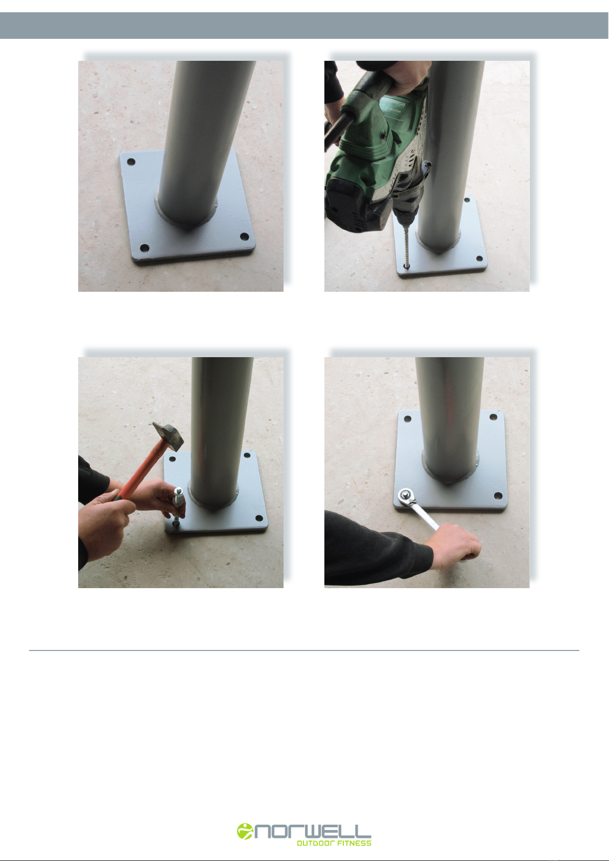
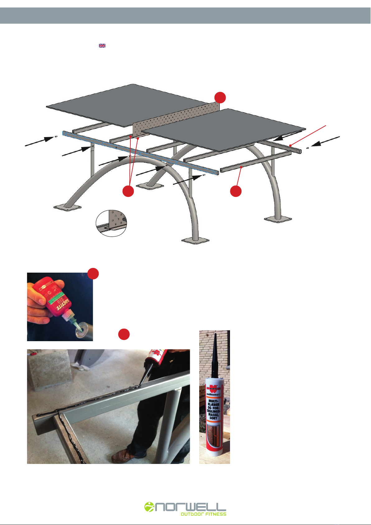
Stellen Sie sicher, dass die Oberfläche sauber
und eben ist.
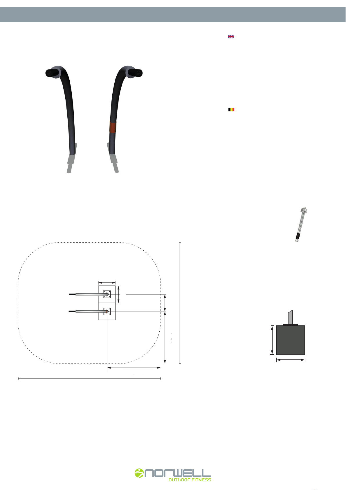
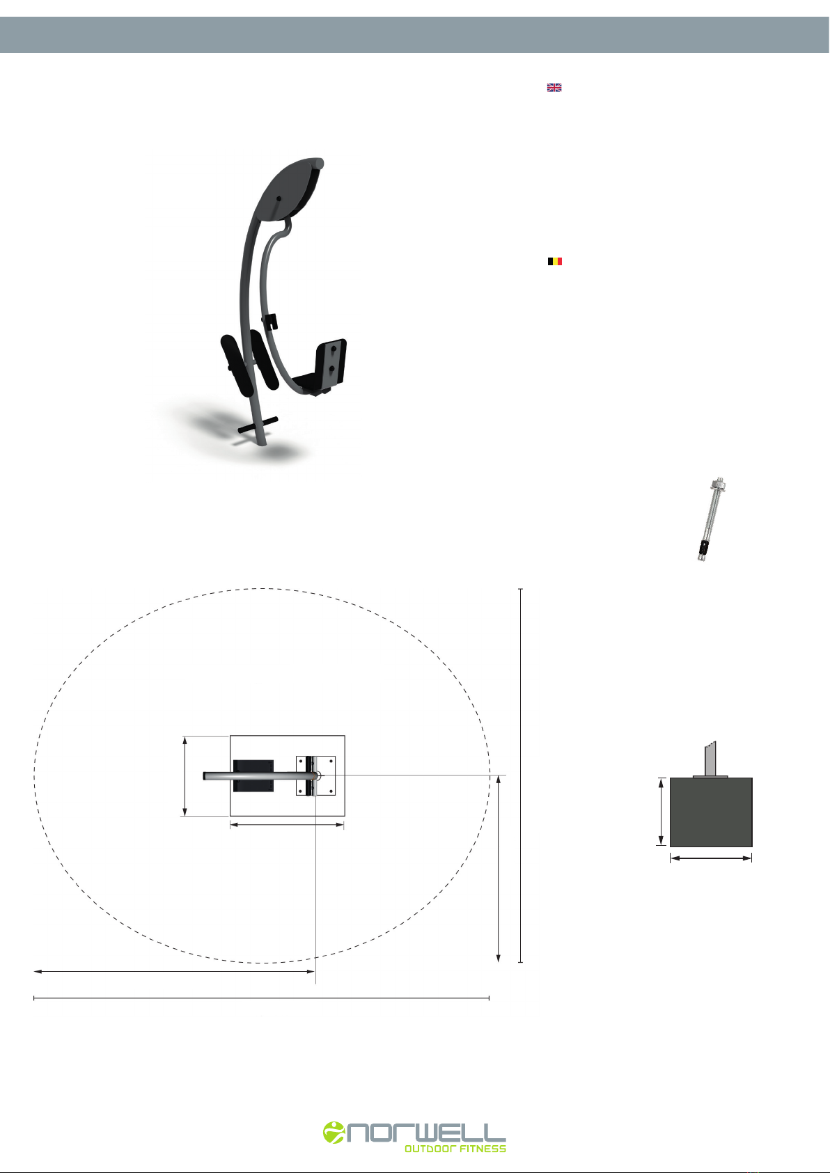
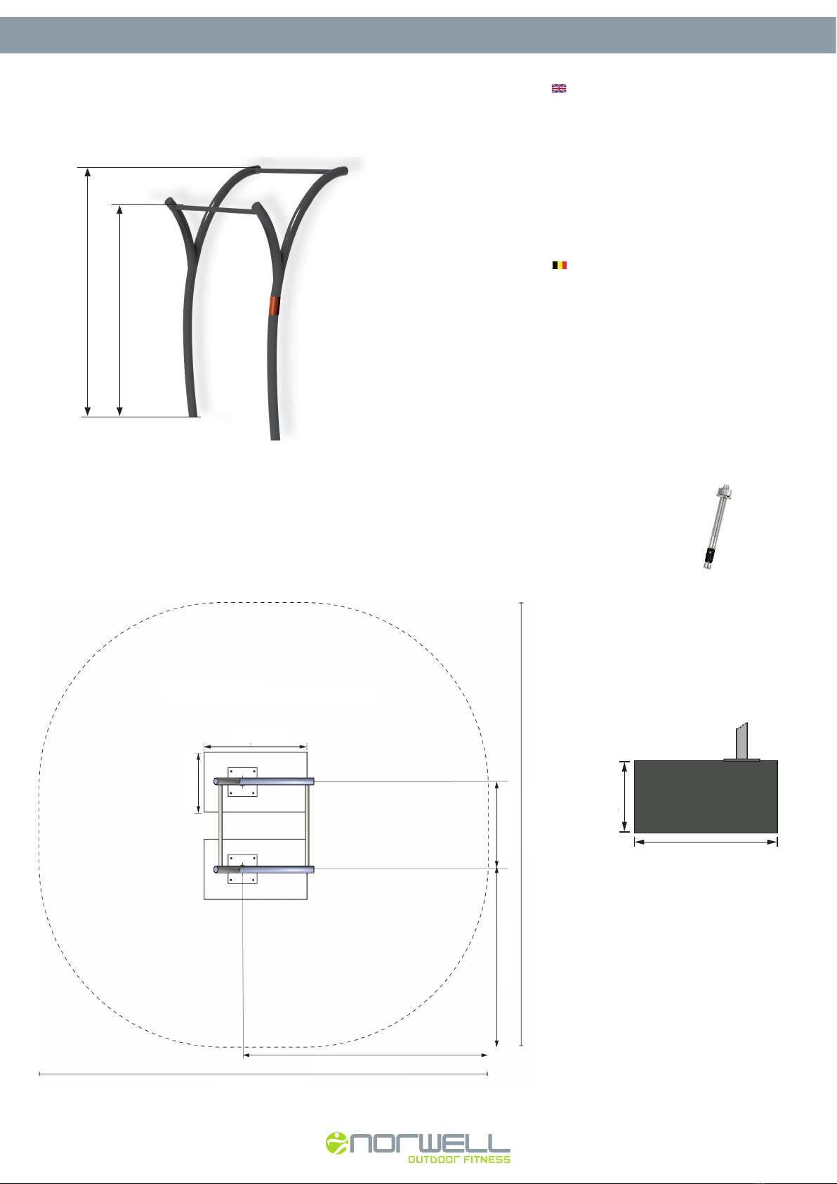
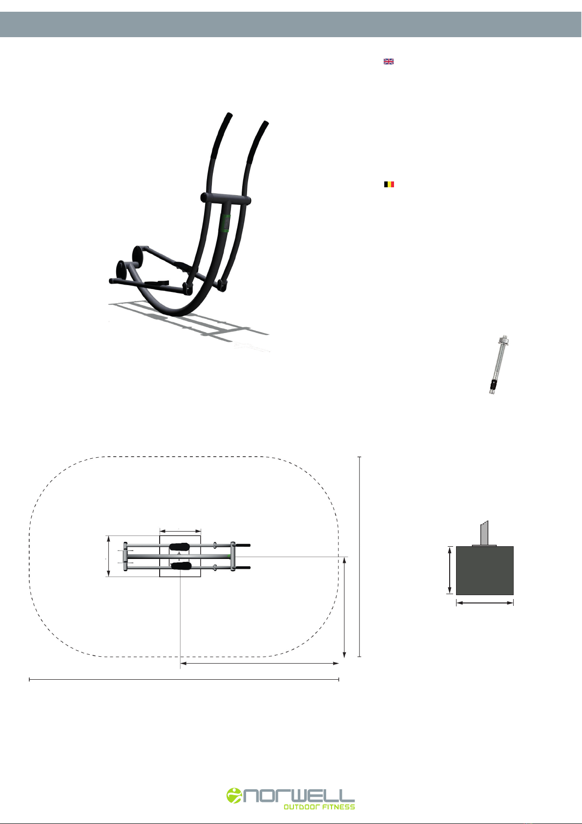
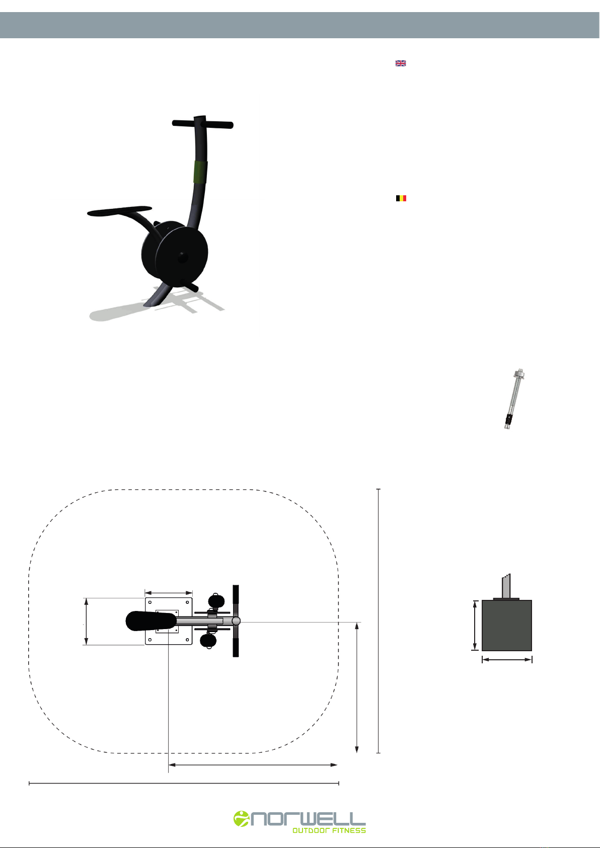
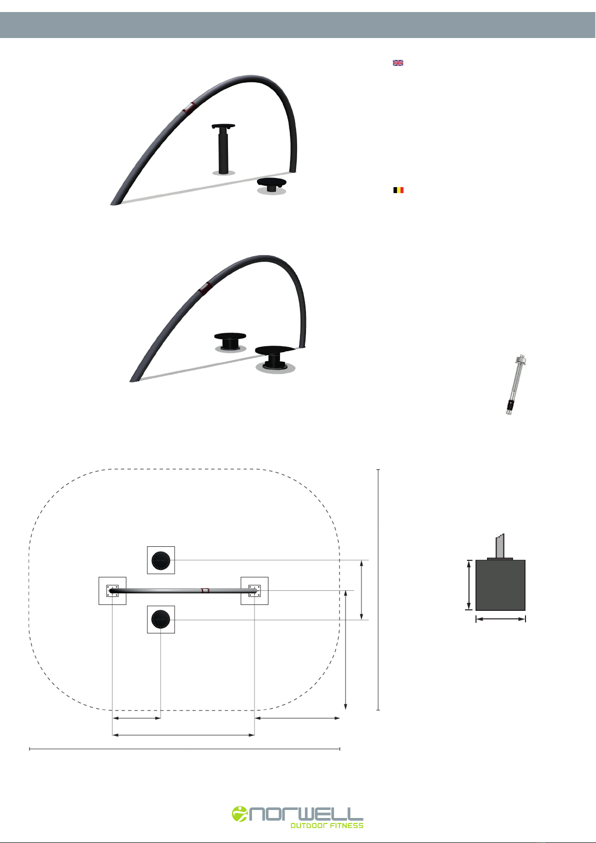
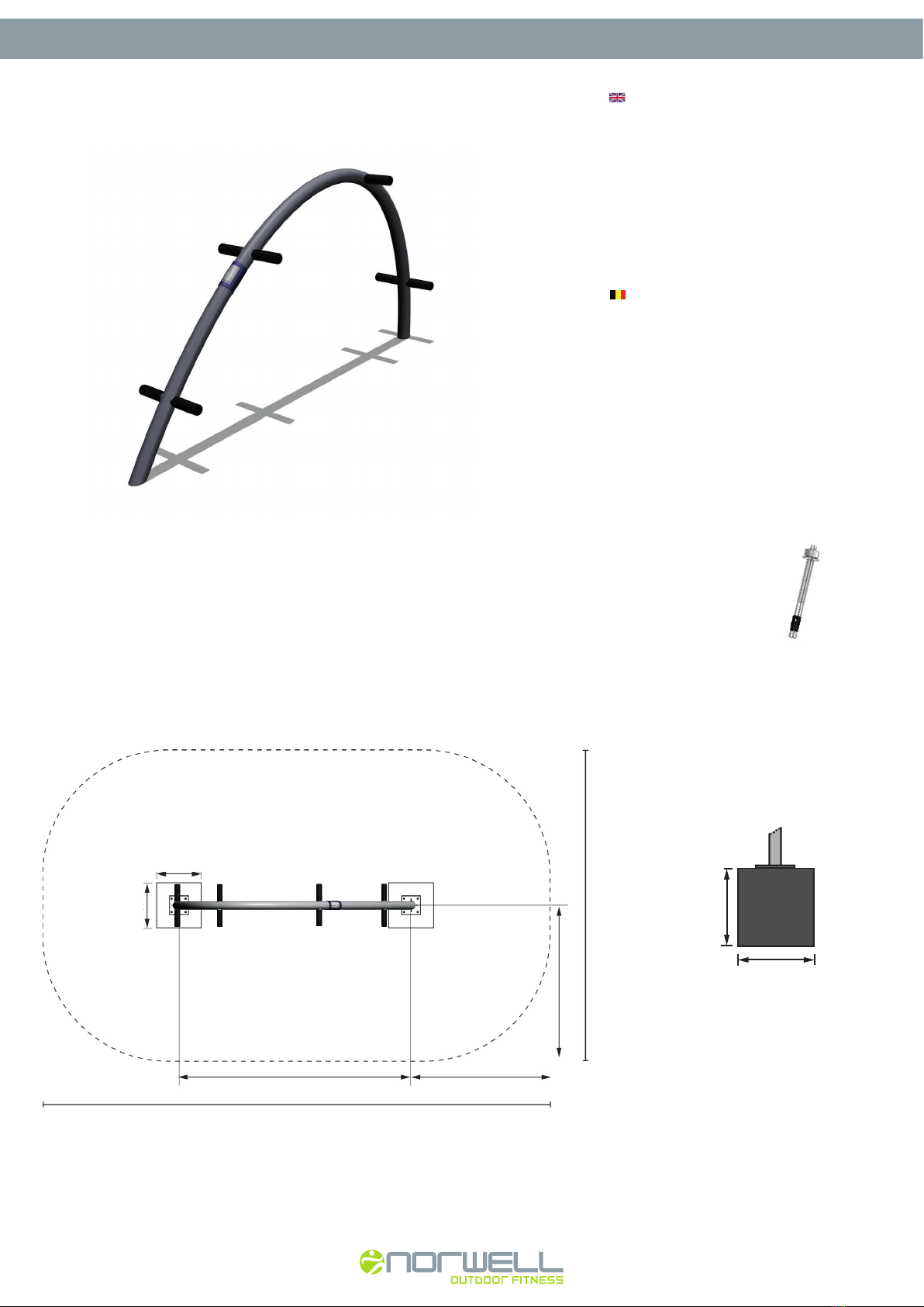
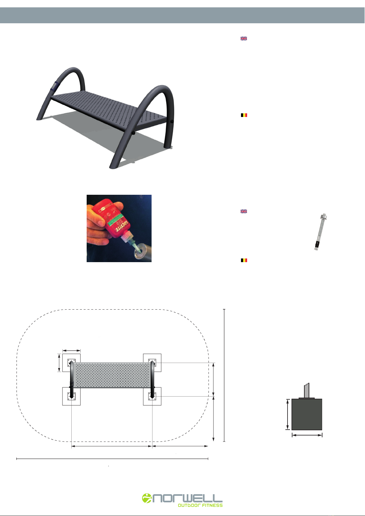
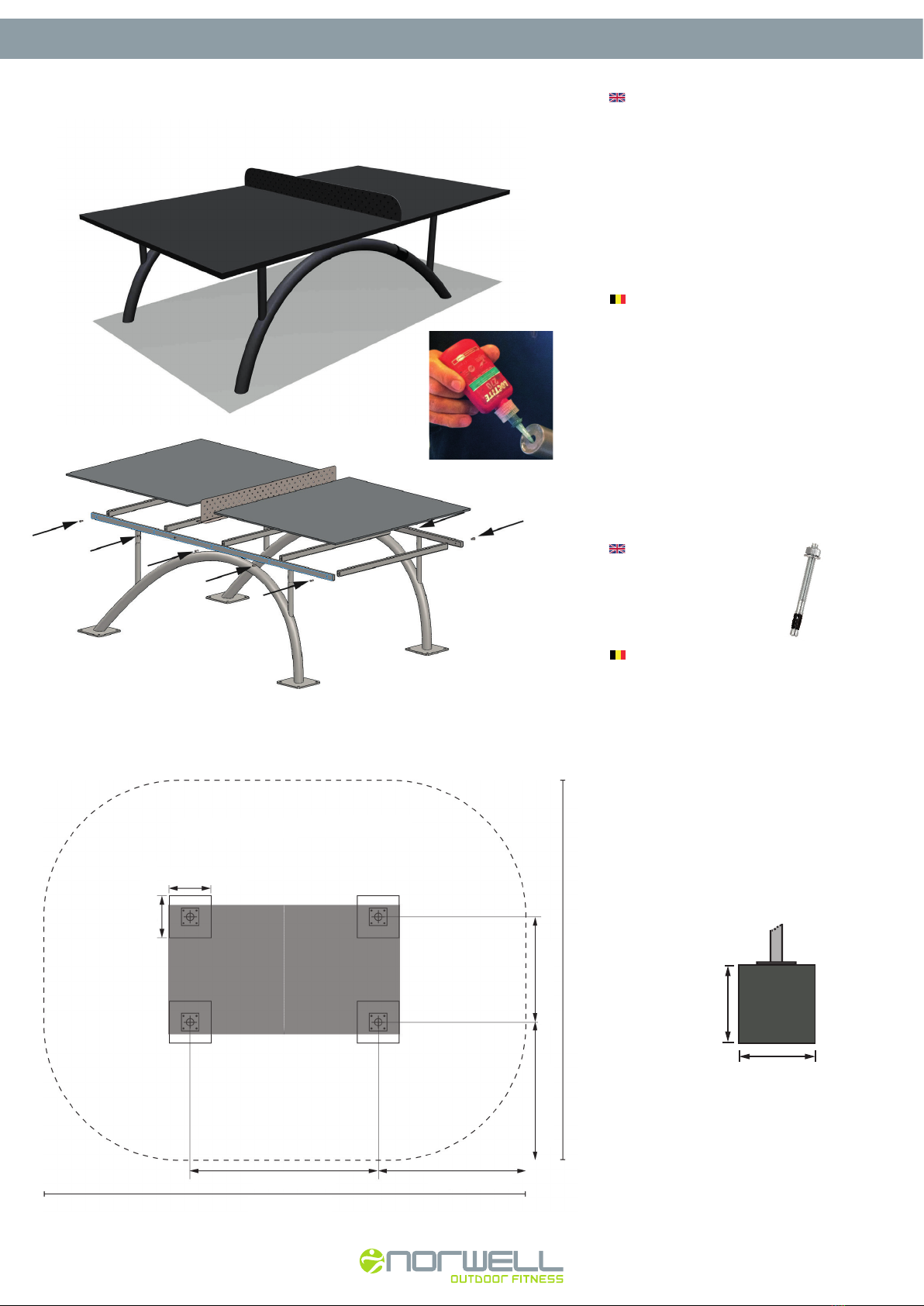
Platzieren Sie die Stationen entsprechend der
Positionen auf den Bildern (sie nächste Seiten).
Bohren Sie Löcher mit einem Bohrhammer.
Befestigen Sie die Schwerlastdübel
M12/M16.
Spannen Sie die Schwerlastdübel mit einem
Drehmoment bei M12 = 90 N/m und
M16 = 120 N/m an und bedecken Sie sie
mit dem gewünschten Oberflächenmaterial.
BETONVORGABEN
Der Beton muss den Standards EN197-1 CEM I 52,5 N
entsprechen.
Mischangaben:
Zement 1/8
Sand 3/8 (max. Steingröße 4mm / 0,2”)
Steine 4/8 (Steingröße 16mm / 0,6”)
Der Beton muss entweder Fertigbeton sein oder in einem
Betonmischer gemischt werden. Mischen von Hand ist
nicht akzeptabel.
Damit der Beton sich setzten kann, muss er mit einem
Betonrütteler verdichtet werden.
Um einwandfreien Kontakt zwischen der Basisplatte
und dem Beton zu gewährleisten, muss der Betonboden
100% eben sein.
Der Beton muss mindestens eine Druckfestigkeit
von ≥52,5 MPa haben (wird nach ca. 7 Tagen
erreicht, länger bei kaltem Wetter).
Die Installation muss von ausgebildeten Fachpersonal
nach neusten Methoden ausgeführt werden.
INSTALLATION MANUAL · SURFACE MOUNT · OBERFLÄCHE
www.norwell.dk · info@norwell.dk COPYRIGHT © 2017 Norwell A/S
4
NW101 Chest NW102 Back
POSITION AND TRAINING ZONE:
POSITION UND TRAININGSZONE:
CONCRETE DEPTH:
BETON TIEFE:
0,50m
0,70m
BETONBLOK
See separate page with the
preparatory work for surface
mount installation.
• Install onto surface.
• Assemble and line up.
• Place on surface.
• Mark position of bolt holes.
• Fasten each base plate with
4 x M16 bolts.
PART LIST:
BESTANDTEIL LISTE:
4 x M16
BASE PLATE:
BASISPLATTE:
40 x 40cm / 16” x 16”
Auf der separaten Seite finden Sie
Angaben zu vorbereitenden Maßnahmen
für eine Installation an der Oberfläche.
• Wird an der Oberfläche installiert.
• Bauen Sie zunächst die Teile
zusammen und stellen Sie sie auf.
• Platzieren Sie sie auf dem Beton.
• Markieren Sie die Positionen der
Schraubenlöcher.
• Fixieren Sie jede Basisplatte mit
4 x M16 Schwerlastdübeln.
CONCRETE
BLOCK /
BETONBLOCK
0,50m/ 20”
0,70m/ 27,5”
12 m 2/ 129 ft2
Training zone =
2,20m / 86,5”
3,90m / 153,5”
3,70m / 145,5”
1,85m / 73”
0,7m / 27,5”
0,7m / 27,5”
INSTALLATION MANUAL · SURFACE MOUNT · OBERFLÄCHE
www.norwell.dk · info@norwell.dk COPYRIGHT © 2017 Norwell A/S
5
NW103 Sit Up See separate page with the
preparatory work for surface
mount installation.
• Install onto surface.
• Assemble and line up.
• Place on concrete.
• Mark position of bolt holes.
• Fasten each base plate with
4 x M12 bolts.
POSITION AND TRAINING ZONE:
POSITION UND TRAININGSZONE:
CONCRETE DEPTH:
BETON TIEFE:
0,50m
0,50m
CONCRETE
BLOCK /
BETONBLOCK
0,50m/ 20”
0,50m/ 20”
PART LIST:
BESTANDTEIL LISTE:
8 x M12
BASE PLATE:
BASISPLATTE:
25 x 25cm / 10” x 10”
Auf der separaten Seite finden Sie
Angaben zu vorbereitenden Maßnahmen
für eine Installation an der Oberfläche.
• Wird an der Oberfläche installiert.
• Bauen Sie zunächst die Teile
zusammen und stellen Sie sie auf.
• Platzieren Sie sie auf dem Beton.
• Markieren Sie die Positionen der
Schraubenlöcher.
• Fixieren Sie jede Basisplatte mit
4 x M12 Schwerlastdübeln.
15m2/ 161,5 ft2
Training zone =
0,5m /20”
0,5m /20”
1,5m /59” 2,05m /80,7”
5,05m /199”
1,70m /67”
3,40m /134”
INSTALLATION MANUAL · SURFACE MOUNT · OBERFLÄCHE
www.norwell.dk · info@norwell.dk COPYRIGHT © 2017 Norwell A/S
6
NW104 Pull Up See separate page with the
preparatory work for surface mount
installation.
• Install onto surface.
• Assemble and line up.
• Place on concrete.
• Mark position of bolt holes.
• Fasten each base plate with
4 x M16 bolts.
POSITION AND TRAINING ZONE:
POSITION UND TRAININGSZONE:
2,35m / 92,5”
1,00m
0,50m
CONCRETE BLOCK /
BETONBLOCK
0,50m/ 20”
1,00m/ 39”
CONCRETE DEPTH:
BETON TIEFE:
PART LIST:
BESTANDTEIL LISTE:
8 x M16
BASE PLATE:
BASISPLATTE:
40 x 40cm / 16” x 16”
Auf der separaten Seite finden Sie
Angaben zu vorbereitenden Maßnahmen
für eine Installation an der Oberfläche.
• Wird an der Oberfläche installiert.
• Bauen Sie zunächst die Teile
zusammen und stellen Sie sie auf.
• Platzieren Sie sie auf dem Beton.
• Markieren Sie die Positionen der
Schraubenlöcher.
• Fixieren Sie jede Basisplatte mit
4 x M16 Schwerlastdübeln.
23m2/ 247,5 ft2
Training zone =
1,0m /39”
0,7m /27,5”
3,20m /126”
5,35m /210,5”
2,10m /82,5”0,98m /38,5”
5,20m /205”
INSTALLATION MANUAL · SURFACE MOUNT · OBERFLÄCHE
www.norwell.dk · info@norwell.dk COPYRIGHT © 2017 Norwell A/S
7
NW105 Bar See separate page with the
preparatory work for surface mount
installation.
• Install onto surface.
• Assemble and line up.
• Place on concrete.
• Mark position of bolt holes.
• Fasten each base plate with
4 x M12 bolts.
POSITION AND TRAINING ZONE:
POSITION UND TRAININGSZONE:
0,50m
0,50m
Auf der separaten Seite finden Sie
Angaben zu vorbereitenden Maßnahmen
für eine Installation an der Oberfläche.
• Wird an der Oberfläche installiert.
• Bauen Sie zunächst die Teile
zusammen und stellen Sie sie auf.
• Platzieren Sie sie auf dem Beton.
• Markieren Sie die Positionen der
Schraubenlöcher.
• Fixieren Sie jede Basisplatte mit
4 x M12 Schwerlastdübeln.
CONCRETE DEPTH:
BETON TIEFE:
PART LIST:
BESTANDTEIL LISTE:
8 x M12
BASE PLATE:
BASISPLATTE:
25 x 25cm / 10” x 10”
CONCRETE
BLOCK /
BETONBLOCK
0,50m/ 20”
0,50m/ 20”
12,5m2 / 134,5 ft2
Training zone =
0,5m /20”
0,5m /20”
0,5m /20”
3,50m /138”
1,50m /59”
1,50m /59”
4,00m /157,5”
INSTALLATION MANUAL · SURFACE MOUNT · OBERFLÄCHE
www.norwell.dk · info@norwell.dk COPYRIGHT © 2017 Norwell A/S
8
NW106 Leg
POSITION AND TRAINING ZONE:
POSITION UND TRAININGSZONE:
0,50m
0,70m
See separate page with the
preparatory work for surface mount
installation.
• Install onto surface.
• Assemble and line up.
• Place on concrete.
• Mark position of bolt holes.
• Fasten each base plate with
4 x M16 bolts.
CONCRETE DEPTH:
BETON TIEFE:
PART LIST:
BESTANDTEIL LISTE:
4 x M16
BASE PLATE:
BASISPLATTE:
40 x 40cm / 16” x 16”
Auf der separaten Seite finden Sie
Angaben zu vorbereitenden Maßnahmen
für eine Installation an der Oberfläche.
• Wird an der Oberfläche installiert.
• Bauen Sie zunächst die Teile
zusammen und stellen Sie sie auf.
• Platzieren Sie sie auf dem Beton.
• Markieren Sie die Positionen der
Schraubenlöcher.
• Fixieren Sie jede Basisplatte mit
4 x M16 Schwerlastdübeln.
CONCRETE
BLOCK /
BETONBLOCK
0,50m/ 20”
0,70m/ 27,5”
1,0m /39”
0,7m / 27,5”
3,40m /134”
1,7m /67”
12 m 2 / 129 ft2
Training zone =
2,07m / 81,5”
3,60m /142”
INSTALLATION MANUAL · SURFACE MOUNT · OBERFLÄCHE
www.norwell.dk · info@norwell.dk COPYRIGHT © 2017 Norwell A/S
9
NW107 Dual Pull Up
2,20m / 86,5”
1,93m / 76”
See separate page with the
preparatory work for surface mount
installation.
• Install onto surface.
• Assemble and line up.
• Place on concrete.
• Mark position of bolt holes.
• Fasten each base plate with
4 x M16 bolts.
POSITION AND TRAINING ZONE:
POSITION UND TRAININGSZONE:
1,00m
0,50m
CONCRETE BLOCK /
BETONBLOCK
0,50m/ 20”
1,00m/ 39”
CONCRETE DEPTH:
BETON TIEFE:
PART LIST:
BESTANDTEIL LISTE:
8 x M16
BASE PLATE:
BASISPLATTE:
40 x 40cm / 16” x 16”
Auf der separaten Seite finden Sie
Angaben zu vorbereitenden Maßnahmen
für eine Installation an der Oberfläche.
• Wird an der Oberfläche installiert.
• Bauen Sie zunächst die Teile
zusammen und stellen Sie sie auf.
• Platzieren Sie sie auf dem Beton.
• Markieren Sie die Positionen der
Schraubenlöcher.
• Fixieren Sie jede Basisplatte mit
4 x M16 Schwerlastdübeln.
23m2/ 247,5 ft2
Training zone =
1,3m /51”
0,7m /27,5”
3,0m /118”
5,35m /210,5”
0,98m /38,5” 2,10m /82,5”
5,20m /205”
INSTALLATION MANUAL · SURFACE MOUNT · OBERFLÄCHE
www.norwell.dk · info@norwell.dk COPYRIGHT © 2017 Norwell A/S
10
NW201 Air Walker See separate page with the
preparatory work for surface mount
installation.
• Install onto surface.
• Assemble and line up.
• Place on concrete.
• Mark position of bolt holes.
• Fasten each base plate with
4 x M12 bolts.
POSITION AND TRAINING ZONE:
POSITION UND TRAININGSZONE:
PART LIST:
16 x M12
1 x cross bar
2 x sets of Nut caps, round
2 x M10x110 bolts
2 x Stainless Steel connector
Auf der separaten Seite finden Sie
Angaben zu vorbereitenden Maßnahmen
für eine Installation an der Oberfläche.
• Wird an der Oberfläche installiert.
• Bauen Sie zunächst die Teile
zusammen und stellen Sie sie auf.
• Platzieren Sie sie auf dem Beton.
• Markieren Sie die Positionen der
Schraubenlöcher.
• Fixieren Sie jede Basisplatte mit
4 x M12 Schwerlastdübeln.
CONCRETE DEPTH:
BETON TIEFE:
BASE PLATE:
BASISPLATTE:
25 x 25cm / 10” x 10”
1 x Handgriff
2 x Set Hutmuttern, rund
2 x M10x110 Bolzen
2 x Verbindungselement aus
rostfreiem Stahl
BESTANDTEIL LISTE:
16 x M12
0,50m
0,50m
CONCRETE
BLOCK /
BETONBLOCK
0,50m/ 20”
0,50m/ 20”
ASSEMBLING:
ZUSAMMENBAUEN:
Always secure bolts
with Loctite.
Sicheren Sie die
Bolzen immer durch das
Benetzten mit Loctite.
16,5m2 / 177,5 ft2
Training zone =
0,5m /20”
0,5m /20”
0,85m /33,5”
1,50m /59”
1,50m /59”
5,50m /216,5”
2,44m /96,1”
3,85m /151,5”
INSTALLATION MANUAL · SURFACE MOUNT · OBERFLÄCHE
www.norwell.dk · info@norwell.dk COPYRIGHT © 2017 Norwell A/S
11
NW202 Cross
POSITION AND TRAINING ZONE:
POSITION UND TRAININGSZONE:
0,50m
0,70m
See separate page with the
preparatory work for surface mount
installation.
• Install onto surface.
• Assemble and line up.
• Place on concrete.
• Mark position of bolt holes.
• Fasten each base plate with
4 x M16 bolts.
CONCRETE DEPTH:
BETON TIEFE:
PART LIST:
BESTANDTEIL LISTE:
4 x M16
BASE PLATE:
BASISPLATTE:
40 x 40cm / 16” x 16”
Auf der separaten Seite finden Sie
Angaben zu vorbereitenden Maßnahmen
für eine Installation an der Oberfläche.
• Wird an der Oberfläche installiert.
• Bauen Sie zunächst die Teile
zusammen und stellen Sie sie auf.
• Platzieren Sie sie auf dem Beton.
• Markieren Sie die Positionen der
Schraubenlöcher.
• Fixieren Sie jede Basisplatte mit
4 x M16 Schwerlastdübeln.
CONCRETE
BLOCK /
BETONBLOCK
0,50m/ 20”
0,70m/ 27,5”
14m2 / 150,5 ft2
Training zone =
5,25m /207”
2,62m /103”
1,80m / 71”
0,7m / 27,5”
3,60m /142”
0,7m / 27,5”
INSTALLATION MANUAL · SURFACE MOUNT · OBERFLÄCHE
www.norwell.dk · info@norwell.dk COPYRIGHT © 2017 Norwell A/S
12
NW203 Stepper
POSITION AND TRAINING ZONE:
POSITION UND TRAININGSZONE:
See separate page with the
preparatory work for surface mount
installation.
• Install onto surface.
• Assemble and line up.
• Place on concrete.
• Mark position of bolt holes.
• Fasten each base plate with
4 x M12 bolts.
0,50m
0,50m
Auf der separaten Seite finden Sie
Angaben zu vorbereitenden Maßnahmen
für eine Installation an der Oberfläche.
• Wird an der Oberfläche installiert.
• Bauen Sie zunächst die Teile
zusammen und stellen Sie sie auf.
• Platzieren Sie sie auf dem Beton.
• Markieren Sie die Positionen der
Schraubenlöcher.
• Fixieren Sie jede Basisplatte mit
4 x M12 Schwerlastdübeln.
CONCRETE DEPTH:
BETON TIEFE:
PART LIST:
BESTANDTEIL LISTE:
16 x M12
BASE PLATE:
BASISPLATTE:
25 x 25cm / 10” x 10”
CONCRETE
BLOCK /
BETONBLOCK
0,50m/ 20”
0,50m/ 20”
15m2 / 161,5 ft2
Training zone =
5,45m / 214,6”
2,45m / 96,5”
1,95m / 77” 1,50m /59”
0,5m /20”
0,45m /17,7”
3,45m /136”
0,9m /35,4”
INSTALLATION MANUAL · SURFACE MOUNT · OBERFLÄCHE
www.norwell.dk · info@norwell.dk COPYRIGHT © 2017 Norwell A/S
13
NW204 Hip
POSITION AND TRAINING ZONE:
POSITION UND TRAININGSZONE:
See separate page with the
preparatory work for surface mount
installation.
• Install onto surface.
• Assemble and line up.
• Place on concrete.
• Mark position of bolt holes.
• Fasten each base plate with
4 x M12 bolts.
0,50m
0,50m
Auf der separaten Seite finden Sie
Angaben zu vorbereitenden Maßnahmen
für eine Installation an der Oberfläche.
• Wird an der Oberfläche installiert.
• Bauen Sie zunächst die Teile
zusammen und stellen Sie sie auf.
• Platzieren Sie sie auf dem Beton.
• Markieren Sie die Positionen der
Schraubenlöcher.
• Fixieren Sie jede Basisplatte mit
4 x M12 Schwerlastdübeln.
CONCRETE DEPTH:
BETON TIEFE:
PART LIST:
BESTANDTEIL LISTE:
8 x M12
BASE PLATE:
BASISPLATTE:
25 x 25cm / 10” x 10”
CONCRETE
BLOCK /
BETONBLOCK
0,50m/ 20”
0,50m/ 20”
19m2 / 204,5 ft2
Training zone =
5,45m / 214,6”
2,45m / 96,5” 1,50m / 59”
1,95m / 76,8”
3,90m / 153,5”
0,5m / 20”
0,5m / 20”
INSTALLATION MANUAL · SURFACE MOUNT · OBERFLÄCHE
www.norwell.dk · info@norwell.dk COPYRIGHT © 2017 Norwell A/S
14
NW205 Cycle
POSITION AND TRAINING ZONE:
POSITION UND TRAININGSZONE:
14m2 / 150,5 ft2
Training zone =
0,7m /27,5”
0,7m /27,5”
2,2m /87”
4,0m /157,5”
3,60m /142”
1,8m /71”
CONCRETE DEPTH:
BETON TIEFE:
BETONBLOK
See separate page with the
preparatory work for surface
mount installation.
• Install onto surface.
• Assemble and line up.
• Place on surface.
• Mark position of bolt holes.
• Fasten each base plate with
4 x M16 bolts.
PART LIST:
BESTANDTEIL LISTE:
4 x M16
BASE PLATE:
BASISPLATTE:
40 x 40 cm / 16” x 16”
Auf der separaten Seite finden Sie
Angaben zu vorbereitenden Maßnahmen
für eine Installation an der Oberfläche.
• Wird an der Oberfläche installiert.
• Bauen Sie zunächst die Teile
zusammen und stellen Sie sie auf.
• Platzieren Sie sie auf dem Beton.
• Markieren Sie die Positionen der
Schraubenlöcher.
• Fixieren Sie jede Basisplatte mit
4 x M16 Schwerlastdübeln.
0,50m
0,50m
CONCRETE
BLOCK /
BETONBLOCK
0,70m/ 27,5”
0,70m/ 27,5”
INSTALLATION MANUAL · SURFACE MOUNT · OBERFLÄCHE
www.norwell.dk · info@norwell.dk COPYRIGHT © 2017 Norwell A/S
15
NW301 Twister
NW302 Springer
POSITION AND TRAINING ZONE:
POSITION UND TRAININGSZONE:
See separate page with the
preparatory work for surface mount
installation.
• Install onto surface.
• Assemble and line up.
• Place on concrete.
• Mark position of bolt holes.
• Fasten each base plate with
4 x M12 bolts.
0,50m
0,50m
Auf der separaten Seite finden Sie
Angaben zu vorbereitenden Maßnahmen
für eine Installation an der Oberfläche.
• Wird an der Oberfläche installiert.
• Bauen Sie zunächst die Teile
zusammen und stellen Sie sie auf.
• Platzieren Sie sie auf dem Beton.
• Markieren Sie die Positionen der
Schraubenlöcher.
• Fixieren Sie jede Basisplatte mit
4 x M12 Schwerlastdübeln.
CONCRETE DEPTH:
BETON TIEFE:
PART LIST:
BESTANDTEIL LISTE:
16 x M12
BASE PLATE:
BASISPLATTE:
25 x 25cm / 10” x 10”
CONCRETE
BLOCK /
BETONBLOCK
0,50m/ 20”
0,50m/ 20”
18,5m2 / 199 ft2
Training zone =
1,5m /59”
2,45m / 96,5”
0,75m /29,5”
0,9m /35,5”
5,45m / 214,6”
4,20m /165”
2,10m /82,5”
INSTALLATION MANUAL · SURFACE MOUNT · OBERFLÄCHE
www.norwell.dk · info@norwell.dk COPYRIGHT © 2017 Norwell A/S
16
NW401 Stretch
POSITION AND TRAINING ZONE:
POSITION UND TRAININGSZONE:
See separate page with the
preparatory work for surface mount
installation.
• Install onto surface.
• Assemble and line up.
• Place on concrete.
• Mark position of bolt holes.
• Fasten each base plate with
4 x M12 bolts.
0,50m
0,50m
Auf der separaten Seite finden Sie
Angaben zu vorbereitenden Maßnahmen
für eine Installation an der Oberfläche.
• Wird an der Oberfläche installiert.
• Bauen Sie zunächst die Teile
zusammen und stellen Sie sie auf.
• Platzieren Sie sie auf dem Beton.
• Markieren Sie die Positionen der
Schraubenlöcher.
• Fixieren Sie jede Basisplatte mit
4 x M12 Schwerlastdübeln.
CONCRETE DEPTH:
BETON TIEFE:
PART LIST:
BESTANDTEIL LISTE:
8 x M12
BASE PLATE:
BASISPLATTE:
25 x 25cm / 10” x 10”
CONCRETE
BLOCK /
BETONBLOCK
0,50m/ 20”
0,50m/ 20”
14m2 / 150,5 ft2
Training zone =
5,45m / 214,6”
1,50m /59”
2,45m / 96,5”
1,70m /67”
3,40m /134”
0,5m /20”
0,5m /20”
INSTALLATION MANUAL · SURFACE MOUNT · OBERFLÄCHE
www.norwell.dk · info@norwell.dk COPYRIGHT © 2017 Norwell A/S
17
NW501 Bench
POSITION AND TRAINING ZONE:
POSITION UND TRAININGSZONE:
See separate page with the
preparatory work for surface mount
installation.
• Install onto surface.
• Assemble and line up.
• Place on concrete.
• Mark position of bolt holes.
• Fasten each base plate with
4 x M12 bolts.
PART LIST:
16 x M12
4 x sets of Nut caps, round
4 x M10 x110 bolts
Auf der separaten Seite finden Sie
Angaben zu vorbereitenden Maßnahmen
für eine Installation an der Oberfläche.
• Wird an der Oberfläche installiert.
• Bauen Sie zunächst die Teile
zusammen und stellen Sie sie auf.
• Platzieren Sie sie auf dem Beton.
• Markieren Sie die Positionen der
Schraubenlöcher.
• Fixieren Sie jede Basisplatte mit
4 x M12 Schwerlastdübeln.
CONCRETE DEPTH:
BETON TIEFE:
BASE PLATE:
BASISPLATTE:
25 x 25cm / 10” x 10”
4 x Set Hutmuttern, rund
4 x M10 x110 Bolzen
BESTANDTEIL LISTE:
16 x M12
0,50m
0,50m
CONCRETE
BLOCK /
BETONBLOCK
0,50m/ 20”
0,50m/ 20”
ASSEMBLING:
ZUSAMMENBAUEN:
Always secure bolts
with Loctite.
Sicheren Sie die
Bolzen immer durch das
Benetzten mit Loctite.
0,5m /20”
16,5m2 / 177,5 ft2
Training zone =
0,5m /20”
1,5m /59”0,88m /34,6”
1,50m / 59”
4,80m / 189”
3,90m /153,5”
1,80m / 71”
INSTALLATION MANUAL · SURFACE MOUNT · OBERFLÄCHE
www.norwell.dk · info@norwell.dk COPYRIGHT © 2017 Norwell A/S
18
NW502 Pingpong
POSITION AND TRAINING ZONE:
POSITION UND TRAININGSZONE:
See separate page with the
preparatory work for surface mount
installation.
• Install onto surface.
• Assemble and line up.
• Place on concrete.
• Mark position of bolt holes.
• Fasten each base plate with
4 x M12 bolts.
Auf der separaten Seite finden Sie
Angaben zu vorbereitenden Maßnahmen
für eine Installation an der Oberfläche.
• Wird an der Oberfläche installiert.
• Bauen Sie zunächst die Teile
zusammen und stellen Sie sie auf.
• Platzieren Sie sie auf dem Beton.
• Markieren Sie die Positionen der
Schraubenlöcher.
• Fixieren Sie jede Basisplatte mit
4 x M12 Schwerlastdübeln.
CONCRETE DEPTH:
BETON TIEFE:
BASE PLATE:
BASISPLATTE:
25 x 25cm / 10” x 10”
0,50m
0,50m
CONCRETE
BLOCK /
BETONBLOCK
0,50m/ 20”
0,50m/ 20”
ASSEMBLING:
ZUSAMMENBAUEN:
Always secure bolts
with Loctite.
Sicheren Sie die
Bolzen immer durch das
Benetzten mit Loctite.
1,25m /49”
21 m 2 / 226 ft2
Training zone =
0,5m /20”
0,5m /20”
2,00m / 78,7”
1,65m /65”
5,50m / 216,5”
1,73m / 68”
4,55m /179”
PART LIST:
16 x M12
10 x M10 x12 bolts
BESTANDTEIL LISTE:
10 x M10 x 12 Bolzen
16 x M12
INSTALLATION MANUAL · SURFACE MOUNT · OBERFLÄCHE
www.norwell.dk · info@norwell.dk COPYRIGHT © 2017 Norwell A/S
19
INSTRUCTION FOR ASSEMBLING
NW502 Ping Pong
See separate page for position, zone
and concrete area requirements.
1Bolt the 5 table top supports
to the side frames.
2Place the net right in the center
vertically and horizontally.
It has the same width as the
table tops.
3Add the Multi Glue on top of
all supports, both upper frames
and on top of the foot of the
net.
4Two people hold one table top
over the frame and all the way
up to the net. Make sure to
center the top on all sides,
lower down and press the top
against frame and supports.
5Repeat with the next table top.
Table top
supports
Foot of
the net
The net
Always secure bolts
with Loctite.
Add the supplied
Multi Glue.
1
2
3
3
1
The side frames
Table top
supports
Foot of
the net
The net
INSTALLATION MANUAL · SURFACE MOUNT · OBERFLÄCHE
www.norwell.dk · info@norwell.dk COPYRIGHT © 2017 Norwell A/S
20
1
2
3
3
1
MONTAGEANLEITUNG
NW502 Ping Pong
Siehe die separate Seite für Anfor-
derungen der Position, der Zone
und des Fundamentes.
1Befestige die 5 Tischplattenstützen
an das Seitengestell.
2Platziere das Netz Vertikal und
Horizontal im Zentrum des
Gestells. Es hat dieselbe Breite
wie die Tischplattenstützen.
3Trage den Multi-Klebstoff auf
allen Oberflächen der Stützen,
sowie auf der Oberfläche der
Füße des Netzes auf.
4Zwei Personen halten eine Tisch-
platte über das Gestell bis hin
zum Netz und zentrieren diese
akkurat zu allen Seiten. Nun wird
die Platte auf das Gestell abge-
senkt und mit Druck angebracht.
5Der gleiche Prozess wird mit der
zweiten Tischplatte wiederholt.
Tischplattenstütze
Fuß
des Netzes
Das Netz
Das Seitengestell
Die Bolzen stets mit
Loctite befestigen.
Trage den
Multi-Klebstoff auf.

Other manuals for NW101 Chest

1

This manual suits for next models

17

Other Norwell Fitness Equipment manuals

Norwell NW101 Chest User manual

Norwell

Norwell NW101 Chest User manual

Norwell NW 101 User manual

Norwell

Norwell NW 101 User manual

Popular Fitness Equipment manuals by other brands

PROSOURCEFIT ADJUSTABLE WEIGHT BENCH Assembly & instruction manual

PROSOURCEFIT

PROSOURCEFIT ADJUSTABLE WEIGHT BENCH Assembly & instruction manual

HOMCOM A91-175 Assembly & instruction manual

HOMCOM

HOMCOM A91-175 Assembly & instruction manual

GPI E-7000 owner's manual

GPI

GPI E-7000 owner's manual

Weider 2990 I Bedienungsanleitung

Weider

Weider 2990 I Bedienungsanleitung

Stamina 55-5557B owner's manual

Stamina

Stamina 55-5557B owner's manual

HOMCOM 800-136 Assembly & instruction manual

HOMCOM

HOMCOM 800-136 Assembly & instruction manual

Sportec PULL-UP 10.0 manual

Sportec

Sportec PULL-UP 10.0 manual

Impulse SL7041 owner's manual

Impulse

Impulse SL7041 owner's manual

Stairmaster 4100PT owner's manual

Stairmaster

Stairmaster 4100PT owner's manual

NICEDAY 701ML user manual

NICEDAY

NICEDAY 701ML user manual

Zonzini Domino Use and maintenance manual

Zonzini

Zonzini Domino Use and maintenance manual

Hammer Quest 6.1 manual

Hammer

Hammer Quest 6.1 manual

GOZONE 42702672 Assembly instructions

GOZONE

GOZONE 42702672 Assembly instructions

Insportline Legro user manual

Insportline

Insportline Legro user manual

Title Boxing RRFSBB Product instructions

Title Boxing

Title Boxing RRFSBB Product instructions

Elite Fitness MC 40 owner's manual

Elite Fitness

Elite Fitness MC 40 owner's manual

Kettler JET Assemnly Instructions

Kettler

Kettler JET Assemnly Instructions

Ironman Fitness 5208 owner's manual

Ironman Fitness

Ironman Fitness 5208 owner's manual

manuals.online logo
manuals.online logoBrands
  • About & Mission
  • Contact us
  • Privacy Policy
  • Terms and Conditions

Copyright 2025 Manuals.Online. All Rights Reserved.