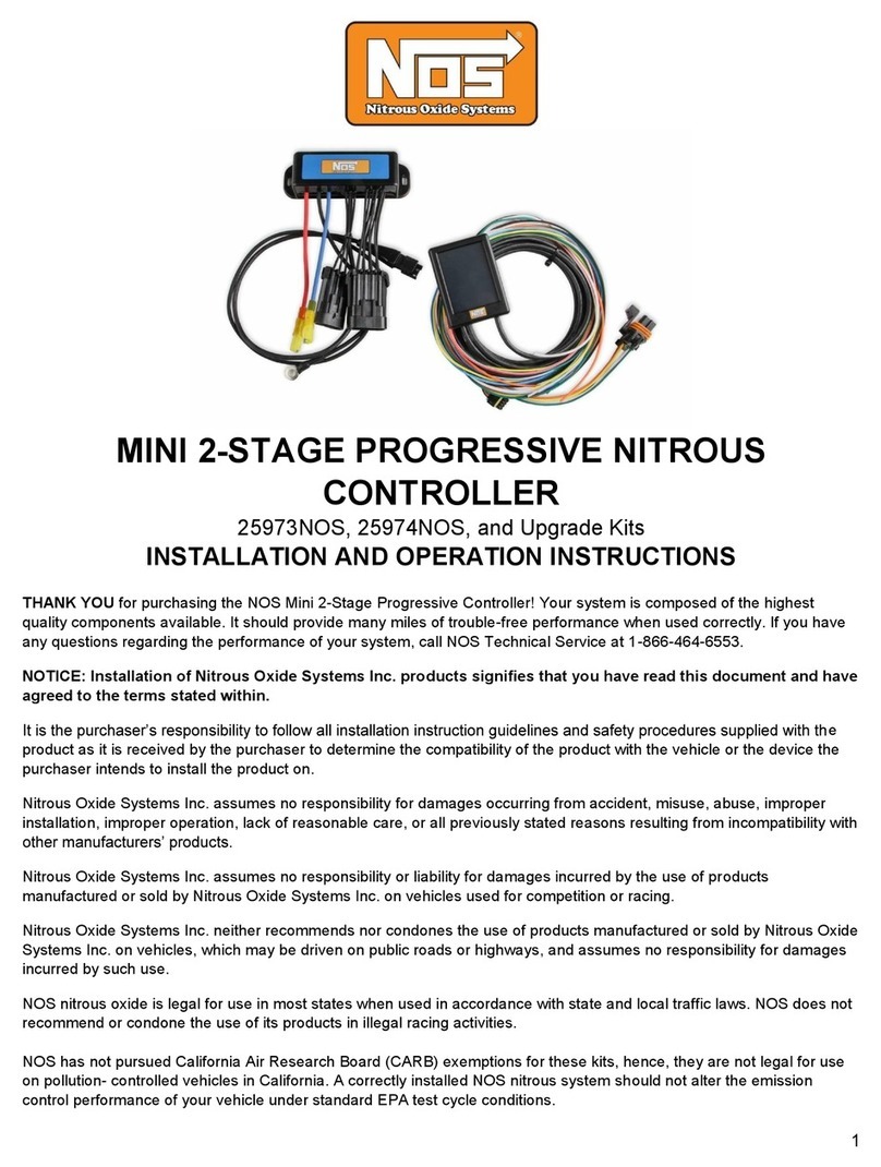
Nos 25973NOS Operating instructions

1
MINI 2-STAGE PROGRESSIVE NITROUS CONTROLLER
25973NOS & 25974NOS
INSTALLATION AND OPERATION QUICK START GUIDE
FEATURES:
The NOS Mini 2-Stage Progressive Nitrous Controller is a fully
featured progressive nitrous controller offering control of up to 2
individual stages and can be fully programmed via a handheld LCD
touch screen display. An SD (Secure Digital) memory card reader is
built-in on the handheld controller to store and upload tunes and is
used for updates.
Solenoid operation can be controlled based on time, RPM, and/or
TPS input and can shut nitrous off at a programmed RPM ceiling.
The configurable nitrous and fuel ramps can be programmed in any
curve shape or with the built-in ramp builder app.
The controller housing is designed and constructed in a manner to
endure the typical harsh conditions found in a racing environment.
The controller can be mounted in the engine or passenger’s
compartment. It is advisable to keep the controller away from direct
heat and severe vibration. Although not required, it is beneficial to
use rubber isolators when mounting the controller on applications
that may see severe tire shake, etc.

2
CONTROLLER INSTALLATION & WIRING:

3
The NOS Mini 2-Stage Progressive Nitrous Controller accepts most
tach signals, including low-voltage and irregular signals, such as
those found on many V-10s. Each channel will drive a fuel or nitrous
solenoid progressively. The Throttle Position Activation Switch
(TPAS) accepts all analog throttle position sensor signals as well as
a “hot” or “grounded” wide-open-throttle (WOT) switch. Both
channels have their own programmable parameters, as well as their
own control output for triggering extra functions, such as ignition
retard. Each channel’s internal TPAS can be configured to prevent it
from activating, unless you are at WOT. Solenoid pulse frequency is
also adjustable to allow the use of different types of solenoids.
Proper grounding is essential to a microprocessor controlled
progressive nitrous controller. The controller has two ground wires
that need to be connected. Proper practice is as follows:
Ground #1 –12 AWG black ground cable –Install this to a good
chassis ground that is grounded securely to the battery as well.
Ground #2 –18 AWG black ground wire –Install this to a “CLEAN”
ground point in the vehicle.
IMPORTANT! A “clean” ground is a ground point that does not
have “dirty” ground attached directly to that point. “Dirty” ground
items consist of any ignition product as well as the 12 AWG black
ground cable from the controller. “Clean” grounds are grounds that
go to sensors or other microprocessor controlled devices. Do NOT
“stack” clean grounds to the same stud/ground point that you attach
“dirty” ground wires to. It is acceptable to run a single ground cable
from the battery to a ground buss bar (multiple ground studs). Stack
“dirty” grounds to one point/stud and attach “clean” grounds to a
separate point/stud.
1. Connect the main 8-pin wiring harness to the controller.
2. Connect the WHITE wire to a +12V fused switched power
source. You should install this to a circuit that has a 5A fuse and

4
can supply two amps to the unit. If this is not available, you
should install a fuse holder.
3. Connect the GREEN wire to the RPM pickup point. You will
define the proper RPM conversion in the software setup. This
wire can go to the typical “tach out” output found on most ignition
boxes and some distributors (12V square wave). For Coil-on-
plug equipped vehicles, it can be connected to one of the
individual coil signal wires, which is typically a ground trigger. For
specific applications, consult a factory service manual.
4. The WHITE/BLUE wire is the “Input 1 Control” wire. This is the
trigger wire used to activate Stage 1. Connect to either a
switched 12V or ground microswitch output. Or, it can be
connected to the signal output wire on a TPS with either a rising
or falling voltage. The signal type is selected in the software
configuration. If you are not sure which wire this is, consult a
factory service manual.
5. The WHITE/RED wire is the “Input 2 Control” wire. This is the
trigger wire used to activate Stage 2. Connect to either a
switched 12V or ground microswitch output. Or, it can be
connected to the signal output wire on a TPS with either a rising
or falling voltage. The signal type is selected in the software
configuration. If you are not sure which wire this is, consult a
factory service manual.
a. NOTE: CH. 1 & CH. 2 trigger input wires can be used together
or separate on the TPS sensor.
6. The YELLOW & ORANGE wires are General Purpose Outputs
(GPO’s) that are programmable in the software for various
purposes such as activating a timing retard, etc. These have
different programmable output that can be set within the
Controllers settings. The YELLOW = Stage 1 Output and the
ORANGE = Stage 2 Output. If these wires will not be used,
heat shrink the end and secure it tightly out of the way.
NOTE: These are low current ground outputs. If using to trigger
a high current device (over 1 Amp), use them to trigger a relay.
7. The 12 AWG BLUE & RED wires are the solenoid ground
outputs. The system works by providing a ground to the
solenoids. These wires are to be connected directly to the

5
solenoids. Power must be supplied separately to the solenoids
by utilizing an appropriate relay. BLUE = Stage 1 Solenoid
Ground Output and RED = Stage 2 Solenoid Ground Output.
NOTE: These channels have a max current rating of 40 AMPS.
8. The 3-pin connector on the main controller is for an optional
nitrous pressure transducer input P/N 15661NOS. This kit
includes the pressure sensor transducer and cable and is sold
separately. Install the sensor at the bottle and plug into the
harness.
9. The 4-pin connector is for the handheld display. This is a
simple plug and play connection. If you are going to
permanently leave the handheld in the vehicle, you will need to
find a factory grommet in your firewall to pass the Display CAN
bus connect through and secure the excess wire away from
hazards. If no factory grommets can be utilized, we recommend
installing one purchased online or from your local auto parts
store.
HANDHELD
The main screen of the NOS Mini 2-Stage Progressive Nitrous
Controller displays: engine RPM, Bottle Pressure (bottle pressure
display can be turned on or off in the dash setup menu), Stage 1 &
Stage 2 activation RPM via colored bars (Blue = Stage 1, Yellow =
Stage 2), Stage 1 & Stage 2 ON/OFF display (ON is only displayed
when the solenoids are actively being trigged). By selecting the gear
icon at the top right corner, you will be directed to the main
menu screen. Here you can select from the menu items. Selecting
the will take you back to the home screen.

6
In the Nitrous Configuration menu, you will be presented with a choice of
three menus –System Setup, Stage 1, & Stage 2. NOTE: The controller will
come pre-programmed with default values. These are only placeholders
and will need to be configured.
STAGE SET UP PROCESS
1. Enter Nitrous Config. Menu and select Stage 1.
2. Enable the stage and input the activation and deactivation RPM
using the slider or manual entry by pressing the number.
3. Run the Ramp Builder App.
4. Enter the Start %, End %, Delay Time, Ramp Time, & Stage
Duration. When satisfied with your inputs press the save button
to configure the Stage 1 Ramp.
5. Go back to the Stage 1 Menu by pressing the back button .
6. (OPTIONAL) The Graph menu will show a visual representation of
what the Ramp Builder created. This curve can be adjusted and
fine-tuned to your preference. Select the desired point by using the
left and right arrows found at the bottom of the screen. The red
highlighted point will show you which point is active. Move the
Go back to the Home
Screen
Enters System Setup,
Stage 1 Setup, & Stage
2 Setup Menus
Save & Upload Tunes
Update Controller,
adjust Home Screen
RPM display limits,
touch screen
calibration, &
enable/disable bottle
pressure display

7
point up or down to the desired location. In the lower right-hand
corner of the graph you will see a time and percentage display.
This will change with the selected point and is used as a reference
to aid you in dialing in the curve. If further fine tuning is required,
simply double tap on the “Stage 1 or Stage 2” title of the graph to
enter a fine tune menu. When satisfied with your curve, press the
save button to save the graph or the back button to exit without
saving the changes.
7. Back on the Stage 1 Menu select the configuration button.
Within the menu you will set up the following:
a. PWM Frequency - NOS Recommends 20 Hz for most of
our solenoids.
b. Ramp/Pause Mode –This allows the controller to either
reset or resume the progressive ramp that has been
programmed once the trigger is deactivated and then
reapplied.
c. TPAS Mode - Throttle position activation switch mode.
Changes the type of throttle input.
d. Control Output Type - Changes the output type for the
stage.
e. Control Output Delay - The time (in seconds) the
controller waits before tuning on the control output.
8. Perform steps 2-7 for Stage 2 if required.
9. Go back to the Nitrous Config. menu and select system setup.
Setup your RPM input type. Use 2-12 cylinders when the tach wire
is connected to the tach from the ECU or distributor –(e.g. CD
ignition box or conventional coil/distributor system). If you selected
TPS to 90% in the TPAS mode, run the TPS autoset app at this
time. Enter the menu with the vehicle ignition switched on but
without the engine running. Observe the resting voltage. Press
start on the handheld and press the accelerator pedal to the floor.
Watch as the TPS voltage changes, you should see a max and min
TPS voltage displayed on the handheld. When complete, press
SET. Note: Your resting TPS voltage may be higher than the WOT
voltage. The controller will account for this and configure the
activation threshold automatically.

8
10. Press the home button to return to the home screen. Your
NOS Mini 2-Stage Progressive Nitrous Controller is now configured
and ready to use.
SAVE/LOAD TUNE
The NOS Mini 2-Stage Progressive Nitrous Controller has the ability to store
and upload tunes. In the main menu you will see the Save/Load Tune
menu. Here you can save your current tune, upload a previous tune, or
upload one of our NOS tunes that have been calibrated for various vehicle
specific nitrous kits. Tunes can be found here:
https://www.holley.com/support/nitrous_oxide_systems/
OTHER OPTIONS
Navigate to the menu screen and press the Contr. Settings button. Within
this menu, you can perform the touch calibration if you run into issues with
the touch screen, view and update the controller firmware, and adjust the
home screen display. With the Dash Setup menu, you can change the min
and max tach display and activate or deactivate the nitrous bottle pressure
display (by default bottle pressure display is disabled).
AN INDEPTH INSTALLATION GUIDE IS AVAILABLE HERE:
https://documents.holley.com/199r11937.pdf
199R11949
Date: 8-28-19
Other manuals for 25973NOS
1
This manual suits for next models
1
Table of contents
Other Nos Controllers manuals
Popular Controllers manuals by other brands
Emerson
Emerson CSB700 Series instruction manual
Genebre
Genebre GNP Installation, operation & maintenance manual
ProMinent
ProMinent DCM510 quick start guide
Deep Sea Electronics Plc
Deep Sea Electronics Plc DSE6110 MKII Installation instructions and instructions for use
ESKA
ESKA ERG-SR Instructions for installation, use and maintenance manual
Enovation Controls
Enovation Controls Murphy EMS PRO LITE Installation and operation manual

