manuals.online logo
Brands
  1. Home
  2. •
  3. Brands
  4. •
  5. HDL
  6. •
  7. Controllers
  8. •
  9. HDL MPR0310.40 User manual

HDL MPR0310.40 User manual

Overview
3CH 10A Flush-mounted Switching Actuator (See Figure 1) is a smart relay executive module installed in
the wall box of the Chinese standard panel. The actuator has the characteristics of exquisite structure and
rich circuits. The actuator adopts HDL Buspro protocol 485 Bus communication control, with 3CH 10A relay
control channels, 7 dry contact signal input channels and 7 LED signal output channels. In conjunction with
the corresponding dry contact panel, the actuator enables smart control of electrical devices, for example,
home lighting, curtain, fan, sockets, etc.
Its main features include:
■With 3CH 10A TV8 relay switch control channels
■With 7 dry contact switch signal input channels, 7 LED switch signal output channels
■With programming button and programming indicator, short press the programming button to control
all relay channels on/off
Note(s)
■Buspro cable - CAT5E or HDL dedicated Buspro cable
■Buspro connection - Hand-in-hand recommended
■Installation - Chinese standard wall box (with the recommended depth of 70mm),the specific use is
determined according to the actual wiring plan.
■Please ensure correct wiring and connection.
■To protect the actuator and loads, it is recommended to connect a 10A circuit breaker to each relay
channel.
■Each LED output channel needs to be connected a resistor in series to the LED (680Ω-1kΩ resistor is
recommended).
■If a resistive load is connected to the relay channel, the maximum load is 10A, and if a capacitive load
is connected to the relay channel, the maximum load is 6A.
■Please use the actuator according to technical data.
Components and Operation
Dimensions - See Figure 2 - 3
Wiring - See Figure 4 - 5
1. Programming button: short press the programming button to control all relay channels on/off
2. Programming button indicator
3. Connection terminal of relay channels
4. Dry contact input interface
5. LED output interface
Safety Precautions
■The installation and commissioning of the device must be carried out by HDL or the organization des-
ignated by HDL. For planning and construction of electric installations, the relevant guidelines, regula-
tions and standards of the respective country are to be considered.
■HDL does not take responsibility for all the consequences caused by installation and wire connection
that are not in accordance with this document.
■Please do not privately disassemble the device or change components, otherwise it may cause me-
chanical failure, electric shock, fire or body injury.
■Please resort to our customer service department or designated agencies for maintenance service.
The warranty is not applicable for the product fault caused by private disassembly.
Datasheet
Issued: November 30, 2020
File Edition: A
1/2
Package Contents
HDL-MPR0310.40*1 / Cable*2 / Datasheet*1
HDL-MPR0310.40
3CH 10A Flush-mounted Switching Actuator
Installation - See Figure 6 - 7
Step 1. Mount the wall box (Chinese standard wall box with 70mm depth) in the wall and draw the AC pow-
er cable and Buspro cable.
Step 2. Make correct wiring for AC power cable and Buspro cable.
Step 3. Put the actuator in wall box with facing outward, and bend the AC power cable and Buspro cable
into the wall box.
Step 4. Plug in the cable between the actuator and the dry contact panel.
Step 5. Mount the panel on the wall box with screws.
Installation
Figure 1. 3CH 10A Flush-mounted Switching Actuator
Figure 3. Dimensions - Side ViewFigure 2. Dimensions - Front View
Figure 4. Wiring
Figure 5. Wiring
22.8mm
50mm
50mm
4
5
HDL Buspro
AC100-240V L
N
1 2
3
Basic Parameters
Working voltage 15~28V DC
Working current 96mA/24V DC
Relay channel 3CH, 10A/CH (AC100-240V, 50/60Hz)
Dry contact 7CH dry contact input
LED 7CH LED output, 12mA/CH
Communication HDL Buspro
Cable diameter of Buspro terminal 0.6-0.8mm
External Environment
Working temperature -5℃~45℃
Working relative humidity ≤90%
Storage temperature -20℃~60℃
Storage relative humidity ≤93%
Specifications
Dimensions 50mm×50mm×22.8mm
Net weight 59g
Housing material Flame retardant PC
Installation Wall box (Figure 6 - 7)
Protection rating (Compliant with EN 60529) IP20
Technical Data
Technical support
E-mail: hdltickets@hdlautomation.com
Website: https://www.hdlautomation.com
©Copyright by HDL Automation Co., Ltd. All rights reserved.
Specifications subject to change without notice. 2/2
Name and Content of Hazardous Substances in Products
Components
Hazardous substances
Lead
(Pb)
Mercury
(Hg)
Cadmium
(Cd)
Chromium VI
(Cr (VI))
Poly-brominated
biphenyls
(PBB)
Poly-brominated
diphenyl ethers
(PBDE)
Plastic o o o o o o
Hardware o o o o - -
Screw o o o ×- -
Solder ×o o o - -
PCB ×o o o o o
IC o o o o ××
The symbol “-” indicates that the hazardous substance is not contained.
The symbol "o" indicates that the content of the hazardous substances in all the homogeneous materials of
the component is below the limit requirement specified in the Standard IEC62321-2015.
The symbol “×” indicates that the content of the hazardous substance in at least one of the homogeneous
materials of the part exceeds the limit requirement specified in the Standard IEC62321-2015.
Figure 6
Figure 7
Figure 6 - 7. Installation
HDL Buspro Cable Guide
HDL Buspro HDL Buspro Cable CAT5/CAT5E
DATA+ Yellow Blue/Green
DATA- White Blue white/Green white
COM Black Brown white/Orange white
24V DC Red Brown/Orange

Other HDL Controllers manuals

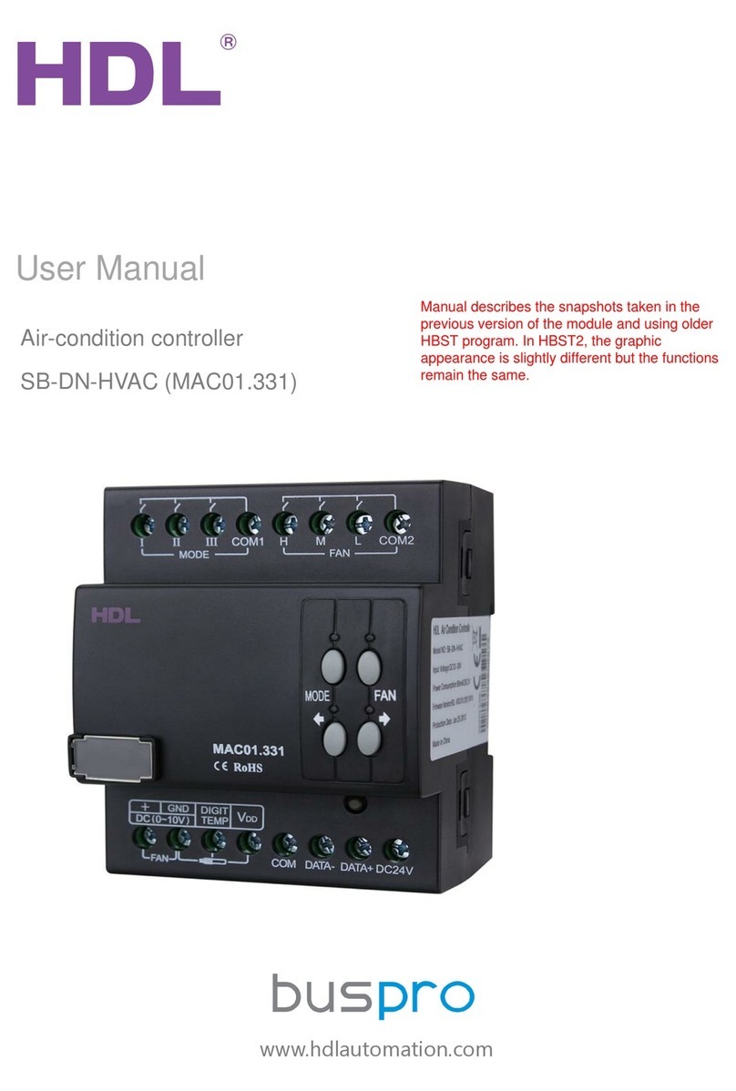
HDL BUSPRO SB-DN-HVAC User manual

HDL

HDL BUSPRO SB-DN-HVAC User manual

HDL HDL-MWM70-RF.12 Instruction Manual

HDL

HDL HDL-MWM70-RF.12 Instruction Manual

HDL SB-DN-512DMX User manual

HDL

HDL SB-DN-512DMX User manual

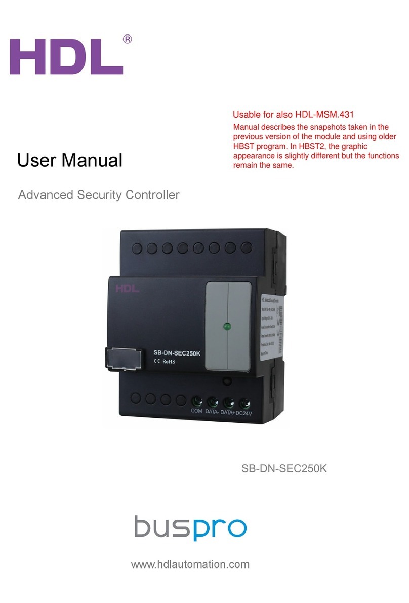
HDL Buspro HDL-MSM.431 User manual

HDL

HDL Buspro HDL-MSM.431 User manual

HDL M/R4.16.1 User manual

HDL

HDL M/R4.16.1 User manual

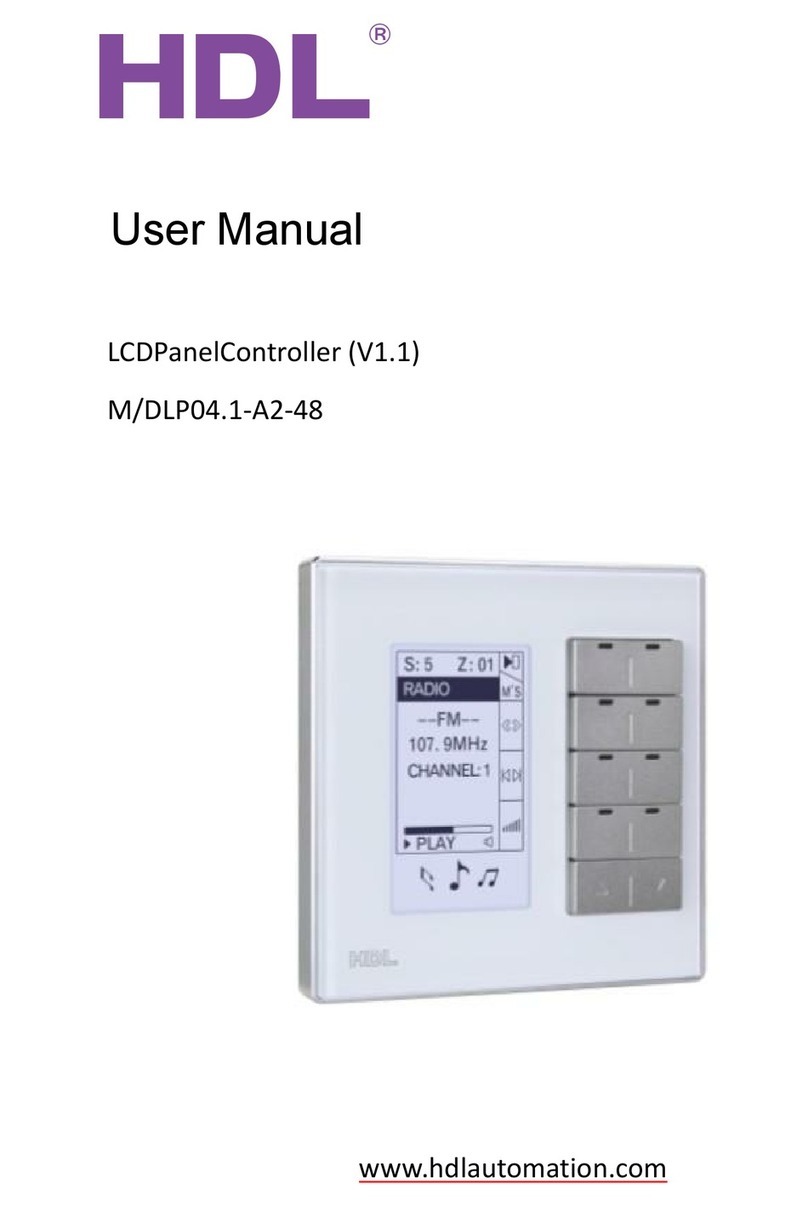
HDL M/DLP04.1-A2-48 User manual

HDL

HDL M/DLP04.1-A2-48 User manual

Popular Controllers manuals by other brands

Honeywell MS4120F Product data

Honeywell

Honeywell MS4120F Product data

Automated Logic LGC Technical instructions

Automated Logic

Automated Logic LGC Technical instructions

V2 DRYS390-R quick start guide

V2

V2 DRYS390-R quick start guide

Siemens FLN installation instructions

Siemens

Siemens FLN installation instructions

Fisher 627F instruction manual

Fisher

Fisher 627F instruction manual

BAGRAM RGB STX-1796 manual

BAGRAM

BAGRAM RGB STX-1796 manual

Airwell WELLEA MONO SPLIT A R32 Operation manual

Airwell

Airwell WELLEA MONO SPLIT A R32 Operation manual

VDO ACTUATORS -  FOR CENTRAL LOCKING SYSTEMS... brochure

VDO

VDO ACTUATORS - FOR CENTRAL LOCKING SYSTEMS... brochure

Siemens RVP331 installation instructions

Siemens

Siemens RVP331 installation instructions

Abbey swampfox SF1 installation guide

Abbey

Abbey swampfox SF1 installation guide

Maintronic CBA UP manual

Maintronic

Maintronic CBA UP manual

Grace m908 user manual

Grace

Grace m908 user manual

Avaya WLAN 8100 Series Regulatory information

Avaya

Avaya WLAN 8100 Series Regulatory information

RMG 330 Operation and Maintenance, Spare Parts

RMG

RMG 330 Operation and Maintenance, Spare Parts

RADEMACHER HomePilot Translation of the commissioning instruction manual

RADEMACHER

RADEMACHER HomePilot Translation of the commissioning instruction manual

IAI RA3R First step guide

IAI

IAI RA3R First step guide

Mitsubishi Electric Central Controller G-50A Operation manual

Mitsubishi Electric

Mitsubishi Electric Central Controller G-50A Operation manual

IBM 3745 Series Connection and Integration Guide

IBM

IBM 3745 Series Connection and Integration Guide

manuals.online logo
manuals.online logoBrands
  • About & Mission
  • Contact us
  • Privacy Policy
  • Terms and Conditions

Copyright 2025 Manuals.Online. All Rights Reserved.