Nova Lock&Load User manual

Vehicle Restraint
Owner’s Manual
© 2013 Nova Technology International, LLC MF2-012-000 October 2013

TABLE OF CONTENTS
SAFETY WARNINGS …………………………………………………………………
COMPONENTS DESCRIPTION …………….…………………………………………
OPERATING PROCEDURES …………………………………………………………
ROUTINE MAINTENANCE ……………………………………………………………
TROUBLESHOOTING …………………………………………………………………
CONTROL HARNESS …………………………………………………………………
ELECTRICAL SCHEMATIC …………………………………………………………..
OUTSIDE LIGHT BOX WIRING ……………………………………………………….
PARTS …………………………………………………………………………………..
NOTES …………………………………………………………………………………….
WARRANTY……………………………………………………………………………..
2NOVA Lock & LoadTM Owner’s Manual
3
4
5
9
11
13
14
15
16
21
23

3NOVA Lock & LoadTM Owner’s Manual
SAFETY WARNINGS
The statements used with this level of
warning deal with a safe operating
procedure. If the procedure is ignored the
possibility of personal injury may exist.
!CAUTION
This is a statement of serious hazard. Failure
to follow the listed instructions could place
the individual at risk of serious injury or
death.
!WARNING
IMPORTANT is used to draw attention to a
procedure that needs to be followed
to prevent machine damage.
IMPORTANT
This is the highest level statement. Failure to
follow the listed instructions will most likely
result in severe injury or death.
DANGER
!
You will find the safety alerts DANGER, WARNING, CAUTION or IMPORTANT used throughout this
manual. Their meaning is listed below:
DO NOT OPERATE THIS PRODUCT UNTIL YOU HAVE READ AND UNDERSTAND THE SAFETY
PRACTICES, WARNINGS AND OPERATING INSTRUCTIONS CONTAINED WITHIN THIS MANUAL.
IMPROPER USE OF THE LOCK & LOAD VEHICLE RESTRAINT COULD RESULT IN SERIOUS
INJURY OR DEATH.
If the Lock & Load vehicle restraint does not operate properly using the procedures in this manual, BE
CERTAIN TO CHOCK THE VEHICLE WHEELS BEFORE LOADING OR UNLOADING. Contact NOVA
or your local representative for service.

NOVA Lock & LoadTM Owner’s Manual
4
COMPONENTS DESCRIPTION
Figure A—Lock & Load Components Description

NOVA Lock & LoadTM Owner’s Manual 5
OPERATING PROCEDURE
Before loading or unloading a vehicle at
your loading dock while using a Lock & Load
vehicle restraint, always visually inspect to
be sure that the restraint is engaged with the
Rear Impact Guard (RIG). If the restraint is
still not engaged after backing the trailer
firmly against the dock bumpers, secure the
trailer by other means.
Be sure that the area around the RIG
assembly is clear of obstructions.
Always operate the Lock & Load vehicle
restraint from the top of the dock.
Inspect all restraint lights daily to make
certain they work properly.
Perform maintenance on restraints in
accordance with Maintenance on page 11 of
this manual.
Lock & Load vehicle restraints should be
operated only by authorized personnel who
have read and understand the Owner’s
Manual.
If you have questions, Call your local
representative or NOVA at (800) 236-7325.
FAILURE TO FOLLOW THESE PROCEDURES
COULD RESULT IN SERIOUS INJURY OR
DEATH.
!WARNING
FIGURE B—STORED POSITION
Stored Position / Restraint UNLOCKED
Hook is in the STORED position. Inside light is
flashing red alerting forklift operator unsafe
condition exists. Outside light is flashing green
alerting truck driver it is safe to back in.
Refer to Figure B.

OPERATING PROCEDURE continued
NOVA Lock & LoadTM Owner’s Manual
6
RESTRAIN Button Pressed -
Restraint ENGAGING
Trailer has backed into loading dock and is
parked firmly against dock bumpers. Hook
rotates from stored position to engage RIG.
Outside light is flashing red alerting truck driver
not to move. Refer to Figure C.
If horn sounds, proceed to FAULT, otherwise
proceed to Restraint ENGAGED.
If trailer can not be restrained due to a lift
gate or other obstruction that could become
damaged, proceed to OVERRIDE.
!CAUTION
Restraint ENGAGED
Once the RIG is engaged by the hook, an
ENGAGED condition exists. Inside light is flash-
ing green alerting the forklift operator a safe con-
dition exists. Outside light is flashing red alerting
truck driver not to move. Refer to Figure D.
If during loading/unloading the inside light turns
red and the horn sounds, press RESTRAIN
button to secure the RIG.
Visually inspect to ensure that the Lock &
Load vehicle restraint hook securely engages
the RIG of the trailer before operating the
dock leveler.
!WARNING
FIGURE D—RESTRAINT LOCKED
FIGURE C—RESTRAINT LOCKING

OPERATING PROCEDURE continued
RELEASE Button Pressed-
Restraint DISENGAGING
Hook travels from the ENGAGED position to the
STORED position. Outside light is flashing red
alerting truck driver not to move. Refer to Figure E.
7
NOVA Lock & LoadTM Owner’s Manual
FAULT from ENGAGING State
Hook cannot engage the RIG. This could be due
to a RIG that is located too far toward the rear
axle, bent, obstructed or missing. Inside light is
flashing red and horn is pulsing, alerting the fork-
lift operator that the trailer is not locked. Outside
light is flashing red alerting the truck driver not to
move. See Figure F.
If the trailer is parked firmly against the dock
bumpers proceed to HORN OVERRIDE. If not,
press RELEASE to clear the fault, have trailer
back up and repeat Restraint ENGAGING.
FIGURE F—FAULT STATE
FIGURE E—RESTRAINT UNLOCKING

NOVA Lock & LoadTM Owner’s Manual8
OPERATING PROCEDURE continued
HORN OVER-RIDE State, KEY
SWITCH TURNED TO OVER-RIDE
after Securing Trailer by Alternate
Means
An alternate means of securing the truck must be
used (e.g. wheel chocks) if the hook can not
capture the RIG. Inside lights are flashing red
and green alerting the forklift operator the trailer
is secured by other means. Outside light is
flashing red alerting the truck driver not to move.
See Figure G.
To return to STORED, turn the HORN OVER-
RIDE key and press the RELEASE button.
FIGURE G—HORN OVER-RIDE STATE

ROUTINE MAINTENANCE
NOVA Lock & LoadTM Owner’s Manual 9
When working with electrical or electronic
controls, make sure that the power source
has been locked out and tagged according to
OSHA regulations and approved local
electrical codes.
Post safety warnings and barricade work ar-
ea, at dock level and at ground level, to pre-
vent unauthorized use of the dock.
DANGER
!
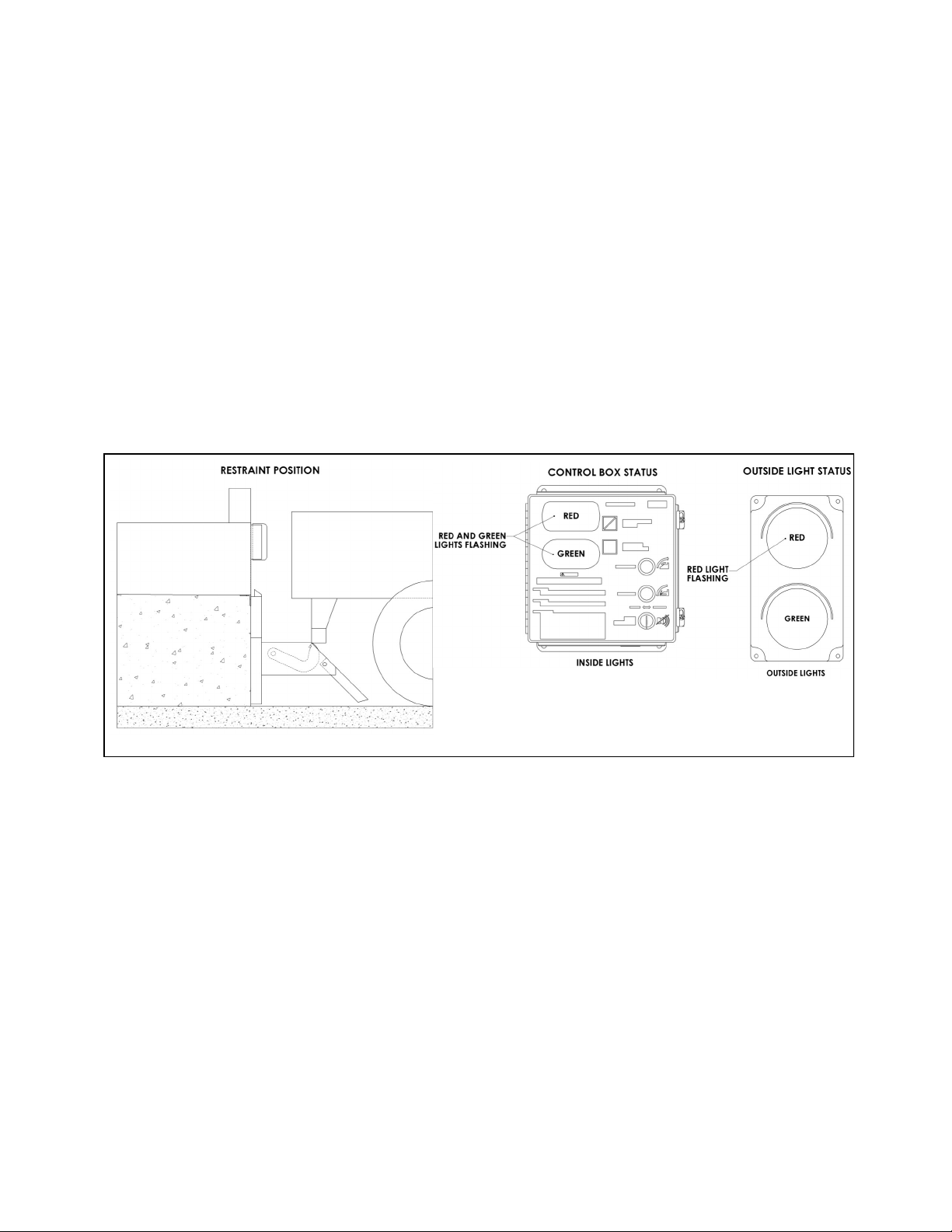
Safe operation of the Lock & Load truck
restraint requires all lights and the
horn to be working properly. DO NOT use
Lock & Load vehicle restraint if parts are
broken or missing.
!WARNING
Use lifting device (e.g. crane, jack) when
lifting carriage (approx. 110 lbs.). Lifting by
hand may cause back injury.
!CAUTION
Maintenance may be required more
frequently at loading docks exposed to harsh
environments (extreme climates, corrosive
chemicals, frequency of usage, etc.). If these
conditions exist, consult NOVA for
accelerated maintenance requirements.
IMPORTANT
NOTE: If a leveler is installed at the Lock & Load
vehicle restraint location, it may be necessary to
raise the leveler before performing maintenance.
Raise the leveler, insert and secure the mainte-
nance strut, and LOCKOUT/TAGOUT the power
source.
DAILY
Remove debris around Lock & Load vehicle
restraint.
Verify that restraint operates smoothly and
inside, outside lights and horn are working.
Replace damaged or missing light bulbs and
lenses.
Repair, remount, or replace outside and
inside signs and labels as required.
Inspect dock bumpers. Missing bumpers must
be replaced.
180 DAYS
Perform all Daily maintenance.
Grease rollers at fittings located on the top
and bottom axle with a synthetic oil-base mo-
ly grease with a temperature range of
–40° to 170° F.
Verify brake torque is greater than 500 in-lbs,
and less than 700 in-lbs at the hook shaft,
rotating the hook from ENGAGED to
STORED.
Inspect the outside electrical connections
(junction box, conduit, power harness) and
outside communication light. Loose or
damaged components must be repaired or
replaced.
Check that all concrete anchor bolts are
torqued to 100 ft-lbs.
Perform operational test after all maintenance
repairs and adjustments are complete.
Inspect dock bumpers. Four inches (4") of
protection is required. Worn, torn, loose or
missing bumpers must be replaced.
360 DAYS
Perform all Daily and 180 Day maintenance.
Check and tighten, if necessary, motor drive
chain. To tighten see Figure H, page 10.
Lube chain using chain lube.
Lubricate limit switch mounting bracket
between drive sprocket and cam with a
synthetic oil-base moly grease with a
temperature range of –40° to 170° F .

ROUTINE MAINTENANCE
NOVA Lock & LoadTM Owner’s Manual
10
DRIVE CHAIN ADJUSTMENT
When working with electrical or electronic
controls, make sure that the power source
has been locked out and tagged according to
OSHA regulations and approved local
electrical codes.
DANGER
!
Inspect the drive chain periodically for dirt and
chain slack. Open the motor enclosure and clean
the chain with solvent. After cleaning, spray with a
high quality chain spray type lubricant.
The drive chain should not have more than 1/4"
slack. Refer to Figure H. To tighten chain:
Open motor enclosure and loosen the four (4)
motor mounting bolts.
Pry the motor assembly forward, in the
slotted holes, until the chain is tight with prop-
er alignment between sprockets.
Hold in this position and tighten the four (4)
motor mounting bolts to 75 in-lbs.
FIGURE H—MAINTENANCE AND LUBRICATION
BRAKE TORQUE ADJUSTMENT
(Refer to Figure H.)
Loosen brake adjuster locknut while holding
the adjuster screw to prevent inadvertent
adjustment.
Turn adjuster screw clockwise to increase
brake torque as needed.
Tighten adjuster locknut while holding the
adjuster screw to prevent inadvertent
adjustment.
Verify brake torque is in the range of 500 to
700 in-lbs at the hook shaft; readjust as re-
quired.

TROUBLESHOOTING
NOVA Lock & LoadTM Owner’s Manual 11
PROBLEM PROBABLE CAUSE RESOLUTION
Lock & Load vehicle restraint
lights do not flash and the
hook does not raise.
Power source malfunction.
Incorrect wiring.
Check power source, including facility
circuit breaker and 1A fuse. and
circuit breaker on power module.
Verify wiring per Electrical Schematic,
Figure K page 14.
Lock & Load vehicle restraint
lights are flashing, but the
hook does not raise or lower to
full extent.
Chain is loose or broken.
Low incoming voltage.
Drive motor defective.
Incorrect wiring.
Adjust or replace as required.
Verify incoming voltage at L1 and L2
is a minimum of 110V. Do not power
off a control transformer from other
equipment unless properly sized for
load.
Check motor. Repair or replace as
needed.
Verify wiring per Electrical Schematic,
Figure K page 14.
Lock & Load vehicle restraint
is operational, but hook drops
causing lights to change and/
or horn to sound while trailer is
being serviced.
Verify brake torque.
Drive motor defective
If brake torque is less than 500 in lb or
chain is loose or broken, adjust or
replace as required.
Check motor. Repair or replace as
needed.
Lock & Load vehicle restraint
is operational but all lights are
out.
Bulbs burnt out, loose or missing.
Incorrect wiring.
Check all bulbs and replace as re-
quired.
Verify wiring per Electrical Schematic,
Figure K page 14.
Lock & Load vehicle restraint
horn does not sound but hook
and lights are operational.
Horn is defective.
Incorrect wiring.
Power horn using 12V DC power. If
horn does not sound, replace as re-
quired.
Verify wiring per Electrical Schematic,
Figure K page 14.
Lock & Load vehicle restraint
hook is in stored position with
an inside green light.
Incorrect wiring. Verify wiring of SW1 and SW2 at the
control box and outside junction box.
Lock & Load vehicle restraint
carriage does not return to a
full up position
Carriage binding in track.
Damaged roller track plate.
Broken or weak springs.
Check to see if roller track plate is
clean and rollers are clean, full of de-
bris and lubricated. Use only ap-
proved grease to lubricate rollers.
Verify that the roller track plate is
straight and not damaged.
Remove spring cover and replace as
required

TROUBLESHOOTING CONTINUED
NOVA Lock & LoadTM Owner’s Manual
12
LIMIT SWITCH TEST PROCEDURE
Set multimeter to “RX1” scale for “Continuity
Test”.
Attach multimeter leads to pins “B” and “C” of
limit switch connector. You should have:
- plunger released - no meter reading.
- plunger depressed - a “Full Scale” meter
reading.
NOTE: The green (ground) wire of the limit switch
does not have to be tested. A continuity test lamp
may be used instead of a multimeter.
FIGURE I—LIMIT SWITCH AND HOOK POSITION CHART

CONTROL HARNESS
NOVA Lock & LoadTM Owner’s Manual 13
FIGURE J—CONTROL HARNESS

ELECTRICAL SCHEMATIC
NOVA Lock & LoadTM Owner’s Manual
14
FIGURE K—ELECTRICAL SCHEMATIC
WIRING PROVIDED BY OTHERS
WIRING PROVIDED BY NOVA TECHNOLOGY
LOCK MOTOR
1/10 HP
3.5 FLA
MOTOR HAS AUTOMATIC
THERMAL OVERLOAD

OUTSIDE LIGHT BOX WIRING
15
NOVA Lock & LoadTM Owner’s Manual
FIGURE L—OUTSIDE LIGHT BOX WIRING

PARTS
NOVA Lock & LoadTM Owner’s Manual
16
CARRIAGE ASSEMBLY DRAWING
FIGURE M —CARRIAGE ASSEMBLY
CARRIAGE ASSEMBLY PARTS LIST
ITEM NO. PART NUMBER DESCRIPTION QTY.
1MF2-015-000 3/8"-16 X 1 1/2" HH CAP SCREW 2
2MF2-061-000 SNAP RING 1
3MF2-047-000 ROLLER ASSEMBLY 4
4MF2-034-000 3/4" CONDUIT NIPPLE 1
5MF2-038-000 LIMIT SWITCH, LS1 1
6MF2-039-000 LIMIT SWITCH, LS2 1
7MF2-094-000 CAM DECAL 1
8MF2-028-000 CAM 1
9MF2-024-000 LIMIT SWITCH MOUNTING PLATE 1
10 MF2-042-000 CHAIN COVER 1

PARTS continued
NOVA Lock & LoadTM Owner’s Manual 17
CARRIAGE ASSEMBLY PARTS LIST continued
ITEM NO. PART NUMBER DESCRIPTION QTY.
11 MF2-026-000 7/16”-14 SERRATED FLANGE LOCK NUT 2
12 MF2-016-000 3/8"-16 SERRATED FLANGE WHIZ NUT 8
13 MF2-041-000 1/4"-20 X 1 1/2" SOCKET HEAD CAP SCREW 2
14 MF2-018-000 1 3/4" OD, 1 1/4" ID, 1/8" THK, MACHINERY BUSHING 2
15 MF2-040-000 1/4" LOCK WASHER 2
16 MF2-095-000 NO STEP DECAL 1
17 MF2-021-000 1/4" X 1/4" X 1 1/4" HOOK KEY 1
18 MF2-023-000 1/4" X 1/4" X 1" KEY, SPROCKET & CAM 2
19 MF2-020-000 HOOK SHAFT 1
20 MF2-037-000 3/4" CONDUIT LOCK NUT 2
21 MF2-022-000 HOOK DRIVE SPROCKET W/SET SCREW 1
22 MF2-019-000 5/16"-18 X 1/2" SK SET SCREW 1
23 MF2-014-000 3/8"-16 X 1" CARRIAGE BOLT 6
24 MF2-117-000 5/16”-18 X 5/8” FLANGE HEAD SCREW 4
25 MF2-033-000 CORD GRIP 1
26 MF2-003-000 STRAIGHT HOOK 1
27 MF2-004-000 CARRIAGE WELDMENT 1
28 MF2-005-000 WIRE HARNESS 1
29 MF2-017-000 LOCK & LOAD BEARING ASSEMBLY 2
30 MF2-017-002 SET SCREW 4
31 MF2-064-000 "LOCK & LOAD" HORIZONTAL DECAL 1
32 MF2-066-000 5/16"-18 X 5/8" SET SCREW 1
33 MF2-068-000 SERIAL NUMBER DECAL 1
34 MF2-080-000 "LOCK & LOAD" LARGE HORIZONTAL DECAL 1
35 MF2-107-000 CHAIN 1
36 MF2-110-000 MF2 MOTOR ASSEMBLY 1
37 MF2-027-000 7/16-14 NYLOCK NUT 1
38 MF2-013-000 GREASE FITTING 2

ITEM NO. PART NUMBER DESCRIPTION QTY.
1MF2-052-000 SPRING COVER RIGHT HAND 1
2MF2-048-000 ROLLER TRACK 1
3MF2-049-000 5/16"-18 CAGE NUT 4
4MF2-050-000 EXTENSION SPRING 4
5MF2-054-000 5/8" X 4" CONCRETE ANCHOR 15
6MF2-051-000 LEFT SPRING COVER 1
7MF2-060-000 5/16"-18 X 1 1/4" FLAT HEAD SOCKET SCREW 4
PARTS continued
NOVA Lock & LoadTM Owner’s Manual
18
ROLLER TRACK ASSEMBLY DRAWING and PARTS LIST
FIGURE N—ROLLER TRACK ASSEMBLY

PARTS continued
19
NOVA Lock & LoadTM Owner’s Manual
SLOPE EXTENSION DRAWING AND PARTS LIST
FIGURE O—SLOPE EXTENSION ASSEMBLY
ITEM NO. PART NUMBER DESCRIPTION QTY.
1MF2-045-000 1" X 18 GAUGE FLAT WASHER 2
2MF2-046-000 COTTER PIN 1
3MF2-044-000 SLOPE EXTENSION PIVOT PIN 1
4MF2-043-000 SPRING MOUNTING PLATE ASSEMBLY 1
5MF2-026-000 7/16"-14 SERRATED FLANGE LOCK NUT 2
6MF2-002-000 SLOPE EXTENSION 1
7MF2-007-000 LOCK & LOAD CARRIAGE ASSEMBLY 1
8MF2-132-000 ROLLER SLOPE EXTENSION 1
9MF2-143-000 5/8” X 3” CLEVIS PIN 1
10 MF2-142-000 COTTER PIN 1
11 MF2-130-000 5/8” SAE FLAT WASHER 1
12 MF2-136-000 ROLLER ASSEMBLY 1

PARTS continued
NOVA Lock & LoadTM Owner’s Manual
20
ELECTRICAL PARTS
FIGURE P —ELECTRICAL PARTS
Table of contents
Popular Automobile Accessories manuals by other brands

Master Tailgaters
Master Tailgaters MR-43-E2DVR3 user manual

Paxton Automotive
Paxton Automotive 1300001 installation manual

Scosche
Scosche BFHA quick start guide

GOWESTY
GOWESTY Yakima installation instructions

Kemo Electronic
Kemo Electronic M180 quick start guide

Maxxhaul
Maxxhaul 80401 Instruction manual & parts list