NOVAERUS Defend 1050 User manual
Document No. NOV-MNL-103
COPYRIGHT ©2021 Novaerus, US
Novaerus, US Inc.
35 Melrose Pl.
Stamford, CT 06902
Phone: 1.866.515.5181
www.novaerus.com
Defend 1050 User Manual
(NV1050)
FDA Cleared
510(k) Class II Medical Device

Table of Contents
1. Intended Purpose . . . . . . . . . . . . . . . . . . . . . . . . . . . . . . . . . . . . . . . . . . . . . . . . . 3
2. Labeling Symbols . . . . . . . . . . . . . . . . . . . . . . . . . . . . . . . . . . . . . . . . . . . . . . . . . . 3
3. ClassicationofEquipment . . . . . . . . . . . . . . . . . . . . . . . . . . . . . . . . . . . . . . . . 4
4. Warnings . . . . . . . . . . . . . . . . . . . . . . . . . . . . . . . . . . . . . . . . . . . . . . . . . . . . . . . . 4
5. TechnicalSpecications . . . . . . . . . . . . . . . . . . . . . . . . . . . . . . . . . . . . . . . . . . . . 6
6. Instructions for Use . . . . . . . . . . . . . . . . . . . . . . . . . . . . . . . . . . . . . . . . . . . . . . . 7
7. Service and Maintenance Instructions . . . . . . . . . . . . . . . . . . . . . . . . . . . . . . . 10
8. Filter Disposal . . . . . . . . . . . . . . . . . . . . . . . . . . . . . . . . . . . . . . . . . . . . . . . . . . . 13
9. Cleaning . . . . . . . . . . . . . . . . . . . . . . . . . . . . . . . . . . . . . . . . . . . . . . . . . . . . . . . . 13
10. Troubleshooting . . . . . . . . . . . . . . . . . . . . . . . . . . . . . . . . . . . . . . . . . . . . . . . . . 14
11. ProductCertications . . . . . . . . . . . . . . . . . . . . . . . . . . . . . . . . . . . . . . . . . . . . 14
12.APPENDIXA.GuidanceandManufacturer’sDeclarations . . . . . . . . . . . . . 15

Document No. NOV-MNL-103
COPYRIGHT ©2021 Novaerus, US 3
1. Intended Purpose
The Novaerus Defend 1050 (NV1050) is a free-standing, portable recirculating
air cleaning system designed for additional frontline protection in healthcare
settings such as operating rooms, intensive care units, in vitro fertilization labs,
emergency rooms, waiting and treatment areas, neonatal units, and other critical
environments including those performing aerosol-generating medical procedures
(AGMP).
Please read and follow all instructions in this manual.
2. Labeling Symbols
Symbol Meaning
Caution, Consult User’s Manual
Caution, High Voltage
Date of Manufacture
Manufactured for or by
Serial Number
This product has been tested by UL to nationally recognized
safety and sustainability standards.
Mains Power Switch On (Power)
Mains Power Switch Off (Power)
Accompanying documents must be consulted
Document No. NOV-MNL-103
COPYRIGHT ©2021 Novaerus, US
4
Indicates the temperature limits to which the medical device
can be safely exposed.
Indicates the range of humidity to which the medical device
can be safely exposed.
3. ClassicationofEquipment
Item Classication
Protection of Harmful Ingress of Water IPX0 (No protection, indoor use only)
Mode of Operation Continuous
Oxygen Rich Environments Not intended for oxygen rich
environments
4. Warnings
GeneralWarnings
CAUTION: This High Voltage (HV) Device is not suitable for use within
atmospheres that contain potentially combustible or explosive dusts,
vapors or gases (including oxygen rich environments).
CAUTION: This device should not be exposed to environmental sterilization
processes such as fogging and misting. Both the water vapor and
chemical agents may cause internal damage to device componentry
thus invalidating the warranty. The active carbon lter may also absorb
the chemical vapor, thereby minimizing the sterilization effects in the
environment, whilst also reducing the operating life of the lter.
CAUTION: The product is not meant to be carried or lifted by the handle.
Castors are provided for mobility, risk of instability if power cord stops
wheels from moving, ensure cord is lifted above the wheels.
CAUTION: Use two or more people to move and handle this unit. Failure to do
so can result in back or other injury. Carefully remove the packaging
materials and any shipping tape before using.
CAUTION: This equipment contains high voltage

Document No. NOV-MNL-103
COPYRIGHT ©2021 Novaerus, US 5
CAUTION: To avoid the risk of electric shock, this equipment must only be
connected to a supply mains with protective earth.
CAUTION: This equipment should be inspected frequently and collected dirt
removed from it regularly to prevent excessive accumulation that may
result in ashover or a risk of re.
CAUTION: No modication of this equipment is allowed.
CAUTION: Do not modify this equipment without authorization of the
manufacturer.
CAUTION: Do not restrict the air ow of the product.
CAUTION: Do not open the tamper proof screws on the casing of the unit. No
serviceable parts are contained within.The units should be opened by
qualied Novaerus personnel only.
CAUTION: Do not use other lters except those supplied by Novaerus. The use
of other brand or no-brand lters with the NV1050 will invalidate
the claims that can be made for the performance of the NV1050.
Novaerus also reserves the right in such situations to refuse warranty
claims.
CAUTION: Do not position the equipment where it is difcult to operate the
power switch.
CAUTION: For continued protection against risk of re, replace the fuse with the
same type and rating, Fuse rated at 120 VAC, 6.3 Amps.
CAUTION: Do not use outdoors or near water.
CAUTION: Not to be used by persons (including children) with reduced physical,
sensory or mental capabilities, or lack of experience and knowledge,
unless they have been given supervision or instruction. Children should
be supervised to ensure that they do not play with the appliance.
CAUTION: To reduce the risk of electric shock, this equipment has a grounding
type plug that has a third (grounding) pin. This plug will only t into a
grounding type power outlet. If the plug does not t into the outlet,
contact qualied personnel to install the proper outlet. Do not alter
the plug in any way.
CAUTION: If the power cord is damaged in any way it must be replaced by a
special cord or assembly available from the manufacturer or its service
agent.
CAUTION: Please remove plastic packaging from lters before use.

Document No. NOV-MNL-103
COPYRIGHT ©2021 Novaerus, US
6
5. TechnicalSpecications
Floor standing, 2-wheeled base +
handle, 5 speed fan setting with 6.6 ft
power cord
Area Coverage:
200 – 1,000 ft2( 4 air changes per
hour)
400 – 2,000 ft2(2 air changes per hour)
Volume Treated:
1,600 – 8,000 ft3(4 air changes per
hour)
3,200 – 16,000 ft3(2 air changes per
hour)
ElectricalRating:
Single phase, 100-120 VAC, 60 Hz
Fuse rated at 120 VAC, 6.3 Amps,
Listed
Power Consumption:
Maximum 396W
Construction + Color:
Precision-cut fabricated metal casing
in a white anti-bacterial powder coat
nish.
Dimensions:
36.2” (h) × 19.3” (w) × 23.2” (d)
Weight
Approx. 118.6 lbs
ElectricalConnection:
Switched and fused with a grounded,
molded and detachable power cord.
FanAirowVolume:
Speed 1 = 107 CFM
Speed 2 = 187 CFM
Speed 3 = 267 CFM
Speed 4 = 400 CFM
Speed 5 = 553 CFM
NoiseLevel:
Speed 1 = 48 dBA
Speed 2 = 56 dBA
Speed 3 = 62 dBA
Speed 4 = 70 dBA
Speed 5 = 78 dBA
Filters:
Stage 1: M5 30/30 lter
Stage 2: HEPA H13 lter, MGA grade
Stage 3: G4 carbon pleated lter
Operating Conditions
50 – 95 °F, 10 - 75% Relative Humidity
Shipping / Storage Conditions
41 – 122 °F, Maximum 95% Relative
Humidity
Quality + Safety:
Manufactured under ISO 9001, ISO
14001 & OHSAS 18001.
IEC 60601-1,Third Edition
IEC 60601-1-2, Fourth Edition
UL 867 Safety for Electrostatic Air
Cleaners
FDA K200321.510(k) Class II Medical
Device

Document No. NOV-MNL-103
COPYRIGHT ©2021 Novaerus, US 7
6. Instructions for Use
a. Transporting the Defend 1050
When transporting the Defend 1050, care should be taken when moving the unit
to the desired location.
The transporter should be positioned close to the back of the unit holding the
transport handle rmly with both hands. The transporter should place one foot
against the base of the Defend 1050 for anchorage and pull the handle slowly
towards them, stepping back on to their other foot.
Stabilize the Defend 1050 at a comfortable angle, depending on the transporters
individual height, where minimal pressure is exerted against the body to ensure
stability.
Once the destination has been reached, allow the unit to gently return to the
upright position. The transporter should place one foot against the base of the
unit and gently extend their forearms, allowing the unit to rest on its front feet.
The Defend 1050 should be placed in a dry location and connected to a suitable
grounded outlet. The product is intended to be used as a oor standing unit only.
Once the product is installed, turn the power switch on the back of the unit to
the ON position. The device is now ready to operate, please use the control
panel to activate the unit to the desired speed.

Document No. NOV-MNL-103
COPYRIGHT ©2021 Novaerus, US
8
Control Panel and Location
The control is located on the top panel of the Defend 1050 near the front of the
unit.
The control panel layout is shown in Figure 1. The control features are listed
below:
Figure 1: Defend 1050 Control Panel layout.
1. ON/OFF power button
2. LED light indicator for ON/OFF power state
3. Airow speed selection button, reduce airow
4. LED lights (5 lights) indicating the active airow speed
5. Airow speed selection button, increase airow
6. LED light indicator of pressure drop check across HEPA lter
7. Pressure drop check button across HEPA lter
b. Power control
The control button on the furthest left-hand side of the control panel is for
switching the device ON/OFF; the power button. The power button is clearly
illuminated with a blue LED to indicate when the device is on. The blue LED is
illuminated when in the ‘ON’ mode and non-illuminated when the device is in
the ‘OFF’ mode.
c. Airowcontrol
The control allows the user to select the device airow using selection button
‘+’ on the right-hand side for incrementing the air ow setting to a higher airow,
and ‘-’ on the left-hand side for decreasing the air ow setting to a lower air ow.
The air ow setting level is clearly indicated by illuminating a series of blue LEDs
in sequence (from left to right) according to the speed setting (e.g. two LEDs for
speed II, three LEDs for speed III). The Defend 1050 has 5 selectable air ow
speeds.
5 6 7
431 2

Document No. NOV-MNL-103
COPYRIGHT ©2021 Novaerus, US 9
d. Saveairowtomemory
There is an ability to save a selected airow to memory so the device will revert
to the last known speed on power-on. The last known speed can be saved to
memory by holding the ON/OFF (1) and ‘-‘ (3) buttons for three seconds. To
revert to factory settings and to clear the air speed memory the ON/OFF (1) and
‘+’ (5) buttons are held for three seconds.
e. HEPAFilterreplacementtest
The HEPA lter replacement test indicator is for information purposes only.
The lter replace button, for testing the lter back pressure, is on the furthest
right-hand side of the panel. Upon pressing the lter back pressure test, the
device shall override the air ow setting to speed 5 air ow for testing the
lter for a period of approx. 30 seconds. The test button shall remain backlit
illuminated blue LED while the device is testing the air pressure.
The device will indicate that the HEPA lter needs to be inspected for
replacement by illuminating the test button in orange or a continuous LED light in
orange.
The device will indicate that the HEPA lter does not need to be inspected by
illuminating the test button in green or a continuous light in green.
Novaerus recommends replacing the HEPA lter every twelve-month (12) period
to ensure optimal performance, or when the lter test check output indicates to
do so; whichever comes rst. Discoloration on the HEPA lter may indicate that
the lter has exceeded its life expectancy. The expected lifetime of these lters is
approximately twelve months (12) under normal clean air conditions (such as that
of a hospital ward).
Document No. NOV-MNL-103
COPYRIGHT ©2021 Novaerus, US
10
7. Service and Maintenance Instructions
a. Service
No serviceable parts are contained within the Defend 1050 unit. The units
should be opened by qualied Novaerus personnel only. The unit is designed
with tamper-proof screws to ensure that it cannot be easily opened by anyone
other than service personnel.
b. Maintenance–ReplacementofFilters
Before replacing lters, ensure the power is switched off at the rear mains switch.
Ensure all lter doors are securely closed before switching the unit back on via
the rear mains switch.
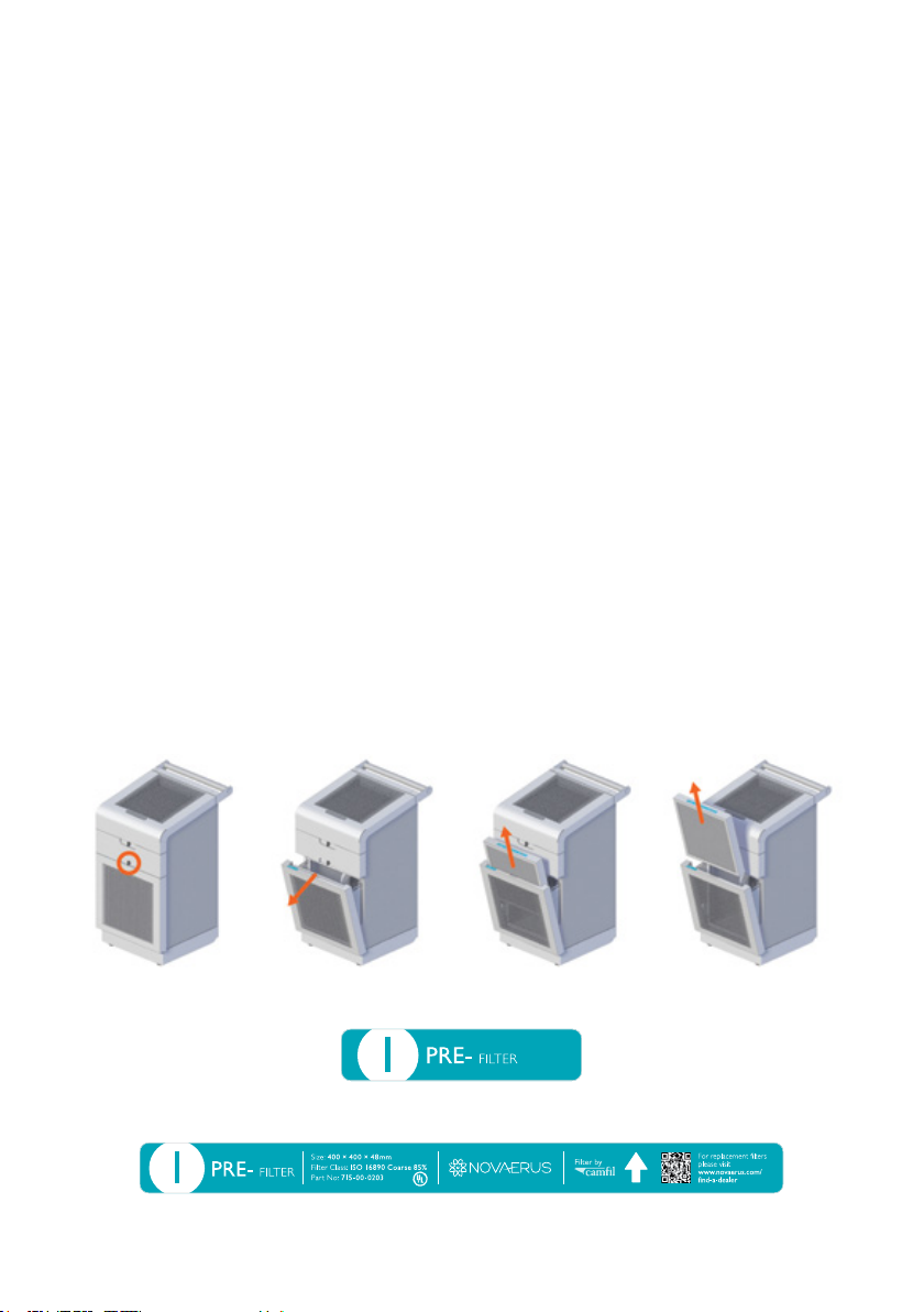
Pre-lter
The intake pre-lter is located behind the front panel of the unit. The pre-lter
should be inspected monthly and be replaced when dirty.
The pre-lter can be removed by unlocking the latch, simply pulling the framing
of the lter outwards and replacing with a new lter.
The metal wire-frame grid should be facing towards the rear of device as shown
in the image below. An airow arrow on the side of the lter shows the correct
direction for the installation of the intake pre-lter screen.
Marking on the Defend 1050 unit corresponding with the required lter.
Markings on the lter to aid placement and correct orientation.

Document No. NOV-MNL-103
COPYRIGHT ©2021 Novaerus, US 11
It is recommended to replace this lter after three (3) months of continuous use.
It is recommended that the user inspect the intake pre-lter screen monthly
during the rst 2 months of use to determine the most appropriate cleaning
period for its facility. If dust and debris has collected on the intake screen
sufcient enough to cause a signicant decrease in airow, more frequent
replacement of this lter may be required.
Only Novaerus supplied replacement lters should be used. Please contact
Novaerus Customer Service for replacement lters.
CarbonFilterandHEPAFilter
The Carbon and HEPA lters are located in the top of the unit and are accessible
by opening the top panel. The Carbon lter should be removed before gaining
access to the HEPA lter.
Marking on the Defend 1050 unit correspond with the required lter.
The Carbon and HEPA lters are tted with a handle that can be used to pull the
lter out of its housing in the Defend 1050 unit.
Carbon Filter
The Carbon Filter can be accessed from the top panel. The orientation of the
lter is indicated on the lter frame itself, see illustration below.

Document No. NOV-MNL-103
COPYRIGHT ©2021 Novaerus, US
12
Markings on the lter to aid placement and correct orientation.
The expected lifetime of the Carbon lter is approximately four months
(4) under normal clean air conditions (such as that of a hospital ward). It is
recommended to replace this lter after four (4) months of continuous use.
Only Novaerus supplied replacement lters should be used. Please contact
Novaerus Customer Service for replacement lters.
HEPAFilter
The HEPA lter can be accessed from the top panel, see illustration below. The
orientation of the lter is indicated on the lter frame itself, see illustration
below. The Carbon lter should be removed before gaining access to the HEPA
lter.
Markings on the lter to aid placement and correct orientation.
Novaerus recommends replacing the HEPA lter every twelve-month (12) period
to ensure optimal performance, or when the lter test check output indicates to
do so; whichever comes rst. Discoloration on the HEPA lter may indicate that
the lter has exceeded its life expectancy. The expected lifetime of these lters is
approximately twelve months (12) under normal clean air conditions (such as that
of a hospital ward).
Only Novaerus supplied replacement lters should be used. Please contact
Novaerus Customer Service for replacement lters.

Document No. NOV-MNL-103
COPYRIGHT ©2021 Novaerus, US 13
8. Filter Disposal
The pre-lter, HEPA and carbon lters are throw-away, dry type air lter units.
The following instructions are for lter disposal for lters used in non-hazardous
environments:
To properly dispose of a used non-hazardous air lter:
• Before you begin, turn off the unit
• Have a plastic bag on hand
• Carefully remove the used air lter from the Defend 1050 unit
• Place the lter gently into the bag, without shaking it. This will prevent
the lter from releasing dust and particles into the air
• Tie or tape the bag shut
• Take the bagged air lter and place it in the waste disposal
For lters used in environmentally hazardous and/or biomedical hazardous air
streams, follow the occupational safety and health administration guidelines in the
country of origin.
9. Cleaning
The unit should be visually inspected for accumulation of dirt and dust on the
vent grills that are located in front and above the unit chassis on a monthly basis.
It is recommended that the unit be cleaned using a vacuum cleaning brush from
the outside of the unit to remove any dirt and dust that may have accumulated
on the grills.
Clean the body of the Defend 1050 regularly to prevent dust from collecting.
1. Wipe away dust from the body of the device with a soft dry cloth.
2. Clean the air outlet with a soft dry cloth.

Document No. NOV-MNL-103
COPYRIGHT ©2021 Novaerus, US
14
10. Troubleshooting
Should the unit sustain severe damage and an increase in noise from the internal
parts is observed, discontinue use of the unit and contact a representative of
the Novaerus technical team for assistance. This product is not intended to be
repaired in the eld.
To ensure the Defend 1050 unit’s optimal functionality when replacing the lters,
the power must be switched off at the rear mains switch before attempting to
open the lter doors. Ensure all lter doors are securely closed before switching
the unit back on via the rear mains switch.
Should the unit power up to an unwanted airspeed, the memory can be cleared
by holding down the ON/OFF button and the ‘+’ button for three seconds.
11. ProductCertications
IEC 60601-1, Third Edition
IEC 60601-1-2, Fourth Edition
UL 867 Safety for Electrostatic Air Cleaners
FDA K200321.510(k) Class II Medical Device
Document No. NOV-MNL-103
COPYRIGHT ©2021 Novaerus, US 15
12. APPENDIXA.Guidanceand
Manufacturer’sDeclarations
Table 201 – Guidance and manufacturer’s declaration – electromagnetic
emissions – for all equipment and systems
Guidance and manufacturer’s declaration – electromagnetic immunity
The NV1050 is intended for use in the electromagnetic environment specied
below. The customer or the user of the NV1050 should assure that it is used in
such an environment.
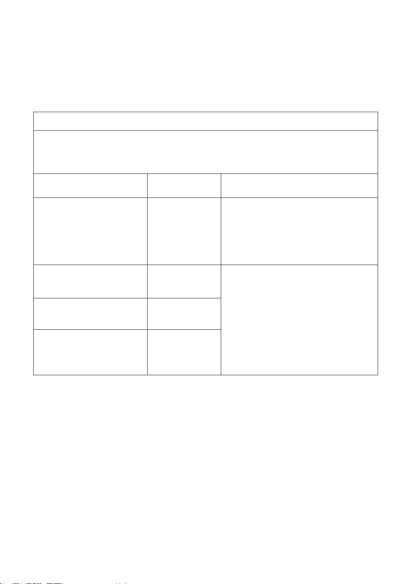
Emissionstest Compliance
RF Emissions
CISPR 11 EN 55011:
2009 + A1: 2010
Group 1
The NV1050 must emit
electromagnetic energy in order
to perform its intended function.
Nearby electronic equipment may
be affected.
RF Emissions
CISPR 11 EN 55011 Class B The NV1050 is suitable for use
in all establishments including
domestic and those directly
connected to the public low-
voltage power supply network
that supplies buildings used for
domestic purposes.
Harmonic emissions EN
61000-3-2 Complied
Voltage uctuations /
icker emissions
EN 61000-3-3
Complied

Document No. NOV-MNL-103
COPYRIGHT ©2021 Novaerus, US
16
Table 202 – Guidance and manufacturer’s declaration – electromagnetic
immunity – for all equipment and systems
Guidance and manufacturer’s declaration – electromagnetic immunity
The NV1050 is intended for use in the electromagnetic environment specied
below. The customer or the user of the NV1050 should assure that it is used in
such an environment.
Immunity
test
IEC60601
Test level Compliance level
Electromagnetic
environment -
guidance
Electrostatic
discharge
(ESD)
EN 61000-
4-2
+/- 8 kV contact
+/- 15 kV air
+/- 2, 4, 6 & 8 kV
contact
+/- 2, 4, 8 & 15
kV air
Floors should be wood,
concrete or ceramic
tile. If oors are
covered with synthetic
material, the relative
humidity should be at
least 30%.
Electrical fast
transient/
burst
EN 61000-
4-4
+/- 2kV for
power supply
lines +/-1 kV
for input/output
lines
+/- 2kV for
power supply
lines +/- 1kV for
input/output lines
Mains power quality
should be that of a
typical commercial or
hospital environment.
Surge EN
61000-4-5
+/- 1kV
differential
mode +/- 2 kV
common mode
+/- 0.5 & 1kV
differential mode
+/- 0.5, 1 & 2 kV
common mode
Mains power quality
should be that of a
typical commercial or
hospital environment.

Document No. NOV-MNL-103
COPYRIGHT ©2021 Novaerus, US 17
Voltage
dips, short
interruptions
and voltage
variations on
power supply
input lines
EN 61000-
4-11
<5 % Ut (>95 %
dip in Ut) for 0.5
cycle @ 0°, 45°,
90°, 135°, 180°,
225°, 270°, 315°
70 % Ut (30 %
dip in Ut) for 25
cycles
<5 % Ut (>95
% dip in Ut) for
5 sec
<5 % Ut (>95 %
dip in Ut) for 0.5
cycle @ 0°, 45°,
90°, 135°, 180°,
225°, 270°, 315°
70 % Ut (30 %
dip in Ut) for 25
cycles
<5 % Ut (>95
% dip in Ut) for
5 sec
Mains power quality
should be that of a
typical commercial or
hospital environment.
If the user of the
NV1050 requires
continued operation
during power mains
operation, it is
recommended that the
NV1050 be powered
from an uninterruptible
power supply or
battery.
Power
frequency
(50/60 Hz)
magnetic
eld
EN 61000-
4-8
30 A/m 30 A/m
Power frequency
magnetic elds
should be at levels
characteristic of a
typical location in a
typical commercial or
hospital environment.
NOTE: Ut is the a.c.mains voltage prior to application of the test level.
continued…

Document No. NOV-MNL-103
COPYRIGHT ©2021 Novaerus, US
18
Table 203 – Guidance and manufacturer’s declaration – electromagnetic
immunity – for equipment and systems that are not life-supporting
Guidance and manufacturer’s declaration – electromagnetic immunity
The NV1050 is intended for use in the electromagnetic environment specied
below. The customer or the user of the NV1050 should assure that it is used in
such an environment.
Immunity
Test
IEC60601TestLevel Compliance Level Electromagnetic
environment guidance
Conducted
RF
EN 61000-
4-6
Radiated
RF EN
61000-4-3
3 Vrms outside
industrial, scientic
and medical (ISM)
and amateur radio
bands.
6 Vrms in ISM and
amateur radio bands
150 kHz to 80 MHz
10 V/m 80 MHz to
2.7 GHz
27 V/m, 18 Hz PM
385 MHz
28 V/m, 50 %18 Hz
PM 450 MHz
9 V/m, 217 Hz PM
710 MHz
9 V/m, 217 Hz PM
745 MHz
9 V/m, 217 Hz PM
780 MHz
28V/m, 18 Hz PM
810 MHz
28 V/m, 18 Hz PM
870 MHz
28 V/m, 18 Hz PM
930 MHz
28V/m, 217 Hz PM
1720 MHz
6 Vrms 150 kHz to
80 MHz
150 kHz to 80
MHz
10 V/m 80 MHz to
2.7 GHz
27 V/m, 18 Hz PM
385 MHz
28 V/m, 50 %18 Hz
PM 450 MHz
9V/m,217HzPM
710 MHz
9V/m,217HzPM
745 MHz
9V/m,217HzPM
780 MHz
28V/m, 18 Hz PM
810 MHz
28V/m,18HzPM
870 MHz
28V/m,18HzPM
930 MHz
28V/m, 217 Hz PM
1720 MHz
28 V/m, 217 Hz PM
1845 MHz
28 V/m, 217 Hz PM
1970 MHz
27 V/m, 217 Hz PM
2450 MHz
Portable and mobile
RF communications
equipment should be
used no closer to any
part of the NV1050,
including cables, than
the recommended
separation distance
calculated from the
equation applicable to
the frequency of the
transmitter.
Recommended
separation distance
d = [1.17] Sqrt P
d = [1.17] Sqrt
P...80MHz to 800 MHz
d = [2.33] Sqrt P...800
MHz to 2.5GHz.
Where P is the
maximum output
power rating of the
transmitter in Watts
(W), according to
the transmitter
manufacturer, and d
is the recommended
separation distance
Document No. NOV-MNL-103
COPYRIGHT ©2021 Novaerus, US 19
28 V/m, 217 Hz PM
1845 MHz
28 V/m, 217 Hz PM
1970 MHz
27 V/m, 217 Hz PM
2450 MHz
9V/m, 217 Hz PM
5240 MHz
9 V/m, 217 Hz PM
5500 MHz
9 V/m, 217 Hz PM
5785 MHz
9V/m, 217 Hz PM
5240 MHz
9 V/m, 217 Hz PM
5500 MHz
9 V/m, 217 Hz PM
5785 MHz
in meters (m), eld
strengths from xed
RF transmitters, as
determined by an
electromagnetic site
survey a, should be less
than the compliance
level in each frequency
range b.
Interference may occur
in the vicinity of
equipment marked
with the
following
symbol:
NOTE1:At 80 MHz and 800 MHz, the higher frequency range applies.
NOTE2:These guidelines may not apply in all situations. Electromagnetic
propagation is affected by absorption and reection from structures, objects and
people.
a. Field strengths from xed transmitters, such as base stations for radio
(cellular/cordless) telephones and land mobile radios, amateur radio, AM
and FM radio broadcast and TV broadcast cannot be predicted theoretically
with accuracy. To assess the electromagnetic environment due to xed
RF transmitters, an electromagnetic site survey should be considered. If
the measured eld strength in the location in which the NV1050 is used
exceeds the applicable RF compliance level above, the NV1050 should be
observed to verify normal operation. If abnormal performance is observed,
additional measures may be necessary, such as re-orientating or relocating
the NV1050.
b. Over the frequency range 150 kHz to 80 MHz, eld strengths should be less
than [V1]V/m.
continued…

Document No. NOV-MNL-103
COPYRIGHT ©2021 Novaerus, US
20
Table 204 – Recommended separation distances between portable and mobile
RF communications equipment and the equipment and system – for equipment
and systems that are not life supporting
Recommended separation distances between portable and mobile RF
communication equipment and the NV1050.
The NV1050 is intended for use in an electromagnetic environment in which
radiated RF disturbances are controlled. The customer or the user of the
NV1050 can help prevent electromagnetic interference by maintaining a
minimum distance between portable and mobile RF communications equipment
(transmitters) and the NV1050 as recommended below, according to the
maximum output power of the communications equipment.
Rated maximum
output power of
transmitter W
Separation distance according to frequency of transmitter m
150 kHz to 80
MHz d = [1.17]
Sqrt P
80 MHz to 800
MHz d = [1.17]
Sqrt P
800 MHz to
2.5GHz d = [2.33]
Sqrt P
0.01 0.12 0.12 0.23
0.1 0.37 0.37 0.75
11.17 1.17 2.33
10 3.70 3.70 7.36
100 11.70 11.70 23.30
For transmitters rated at a maximum output power not listed above, the
recommended separation distance d in meters (m) can be estimated using
the equation applicable to the frequency of the transmitter, where P is the
maximum output power rating of the transmitter in watts (w) according to the
transmitter manufacturer.
NOTE1 At 80 MHz and 800 MHz, the separation distance for the higher
frequency range applies.
NOTE2 These guidelines may not apply in all situations. Electromagnetic
propagation is affected by absorption and reection from structures, objects and
people.
This manual suits for next models
1
Table of contents
Other NOVAERUS Air Cleaner manuals


