field guide
•For Timbuk2 ESCs with ROCK BOOST•
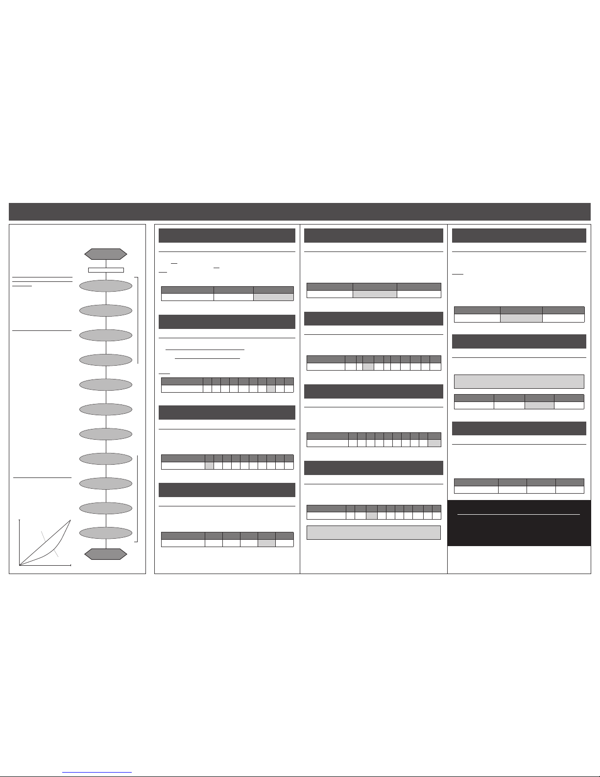
proper gear selection
4-2014
#55-1832P-1 Rev.5
Motor operating temperature is the ONLY
way to properly set vehicle gearing
The Motor and Speed Control should not exceed
160°F MAX at any time during run!
Change the gearing to avoid overheating!
DO NOT FREE-REV MOTOR
!
Free-running your brushless motor in a no-load condition can cause rotor failure
& ESC transistor damage that will not be covered by the product’s warranty.
Because of the potential danger of overheating and ESC/motor damage and
failure, you must start with VERY small pinion sizes and check the speed
control and motor operating temperatures at multiple times throughout the
initial runs after installation. This is the only way to ensure that you are not
causing excessive heating.
If ESC & motor temperatures remain low & stable, you can slowly increase
the pinion size while again monitoring the temperatures to determine the
safe gearing for your vehicle, motor, and climate/track conditions. Because
these variables can change or be modified, you MUST continually monitor
ESC & motor temperatures to protect your electronics from damage.
This Brushless Electronic Speed Control (ESC) is factory loaded with
programmable features. While this may seem overwhelming at first
glance, this Field Guide is designed to keep with you out on the rocks to
use as a quick-reference and help walk you through the programming
of all of the speed control’s features.
Take the time to thoroughly read through this programming guide
before attempting to make any programming adjustments so you
fully understand the different ESC parameters, and how they can be
used to fine tune your ESC’s feel and performance. Most importantly,
enjoy all of the technical benefits and features the ESC has to offer.
Visit our web site for the most up to date information and to learn
more about other Novak products and services.
www.teamnovak.com
trouble-shooting guide
Steering Channel Works But Motor Will Not Run
• Possible receiver damage––Check operation with a different receiver.
• Possible internal damage––Refer to ‘SERVICE PROCEDURES’ section.
• Check motor or motor connections.
•
Check ESC is plugged into receiver’s throttle channel. Check signal harness wire sequence.
Receiver Glitches/Throttle Stutters During Acceleration
• Receiver or antenna too close to ESC, power wires, battery, or motor.
• Bad motor sensors, sensor harness, or connections––Check wiring, sensor harness, &
connections, perform hall sensor test (Refer to ‘MOTOR HALL SENSOR TEST’ section).
•
Low voltage to receiver––Try Novak Glitch Buster (#5626) on receiver to retain power.
• PowerCap damaged/missing––Replace PowerCap/Trans-Cap Module.
• Battery pack damaged or weak––Try a different battery pack.
• Motor magnet weak or overheated––Replace rotor
(Refer to motor manufacturer’s website
).
• Excessive current to motor—Use a milder motor or a smaller pinion gear.
• Untidy wires or signal and power wired bundled together. Input harness and servo
wires should be bundled separately. Power wires should be as short as possible.
Motor and Steering Servo Do Not Work
• Check wires, receiver signal harness wiring & color sequence, radio system, crystals,
battery/motor connectors, & battery pack.
• Possible receiver damage––Check operation with a different receiver.
• Possible internal damage––Refer to Service Procedures.
Motor Runs Backward
• Reverse motor rotation direction––Refer to
‘CUSTOM PROGRAMMING OPTIONS’
section.
• Improper One-Touch set up––Refer to ‘ONE-TOUCH PROGRAMMING’ section.
Speed Control Runs Excessively Hot
•
Gear ratio too low––Increase gear ratio/Reduce pinion
(refer to ‘PROPER GEAR SELECTION’).
• Motor is damaged––Try a different motor.
Model Runs Slowly/Slow Acceleration
•
Gear ratio too high––Reduce gear ratio/Increase pinion
(refer to ‘PROPER GEAR SELECTION’).
• Check battery & connectors––Check battery pack & connectors. Replace if needed.
• Incorrect transmitter/ESC adjustment––Refer to ‘TRANSMITTER ADJUSTMENTS’.
• PowerCap damaged/missing––Replace PowerCap or Power Trans-Cap Module.
ESC Is Melted Or Burnt/ESC Runs With Switch Off
• Internal damage––Refer to Service Procedures.
No Power to the BEC
• Check power wire connections to your battery, ESC and BEC unit.
•
Check BEC input harness is plugged into receiver & ESC’s red wire is removed from harness.
• Be sure that the BEC unit switch is turned ON.
error/LED codes
• Blue status LED on solid at neutral––Minimum Brake is set to value greater than 0%.
• Yellow status LED on solid at neutral––Drag Brake is set to value greater than 0%.
• Red & Green status LEDs on solid––Check input signal harness connections at ESC and
receiver. Check input signal harness wiring sequence––Refer to STEP 3.
• Red status LED on solid & Green LED blinking––Check motor sensor harness connection.
Possible internal motor damage.
•
Blue & Green status LEDs both blinking. Misfire shut-down––return throttle to neutral
position to regain motor control––check drive train for free operation.
• Blue & Red status LEDs blinking. Possible ESC thermal shut-down––Check gear ratio
& free operation of drive train for possible overloading/ESC is being severely over-
loaded––allow system to cool & return throttle to neutral position to regain motor
control. LEDs will continue to blink until system is cooled down.
• Blue & Yellow status LEDs blinking. Possible Motor thermal shut-down––Check gear
ratio & free operation of drive train for possible overloading/Motor is being severely
over-loaded––allow system to cool & return throttle to neutral position to regain
motor control. LEDs will continue to blink until system is cooled down.
• Blue & Green (Misfire Detection), Blue & Red (ESC Thermal Shut-Down), or Blue &
Yellow (Motor Thermal Shut-Down) status LEDs blinking. ESC may have shut-down &
ESC’s neutral point is too far off to sense that transmitter throttle has been returned
to neutral (Refer to ‘ONE-TOUCH’ & ‘TRANSMITTER ADJUSTMENTS’).
•
Red & Yellow status LEDs toggling. LiPo/LiFe Cut-Off voltage reached. Recharge battery.
service procedures
Before sending your product in for service, review the Trouble-Shooting Guide. Product
may appear to have failed when other problems exist. After reviewing instructions, if you
feel that you require service, obtain the most current service options & pricing as follows:
WEB: Print out the PRODUCT SERVICE FORM from CUSTOMER SERVICE
section of the web
site. Fill out required information on form and return it with the product requiring service.
WARRANTY SERVICE: You MUST CLAIM WARRANTY on PRODUCT SERVICE FORM & include
a valid cash register receipt with purchase date, dealer name, & phone# on it, or a previous
service invoice. If warranty provisions have been voided, there will be service charges.
• ESCs returned without a serial number will not be serviced under warranty •
TRADE-IN PROGRAM: Novak offers a trade-in program for non-warranty items toward
current and discontinued products. You can replace, exchange, or upgrade Novak products
as listed within the trade-in program. Complete a Non-Warranty Service Form to be eligible.
ADDITIONAL NOTES:
•
Dealers/distributors aren’t authorized to replace products thought to be defective.
• If a hobby dealer returns your product for service, submit a completed PRODUCT
SERVICE FORM to the dealer and make sure it is included with product.
• Novak R/C, Inc. does not make any internal electronic components (transistors,
resistors, etc.) available for sale.
one-touch programming
esc parameters
motor hall sensor test
The following parameters are adjustable to help fine-tune the feel and
response of the speed control to your liking:
1. Rock Boost (1 of 2) .......................................................... OFF/ON
2. Standard Drag Brake--Settings 1-5 (1 of 5) ....................... 0-100%
Power Hill/Hold Brake--Settings 6-10 (1 of 5) ................... 40-90%
3. Minimum Drive (1 of 10) ................................................... 0-15%
4. Dead Band (1 of 5) ..............................................................2-8 %
5. Throttle Curve (1 of 2) .....................................Linear/Exponential
6. Brake Frequency (1 of 10) .......................................1.67-13.7 KHz
7. Brake End Point (1 of 10) ...............................................10-100%
8. Drive Frequency (1 of 10) ...............................................7-16KHz
9.
Motor Rotation (1 of 2) ................................................. CCW/CW
10.
Voltage Cut-Off (1 of 3) ......................................... OFF-LiPo -LiFe
The Hall Sensor Test diagnostic feature in this ESC allows you to easily check the
sensors in the brushless motor connected to it to determine if they are operating
normally. This will help you pinpoint the cause of problems in your system, and
hopefully reduce the down time and expenses associated with sending your
product in for service when you can resolve the issue yourself.
To access this feature, simply follow these steps:
1. Follow the steps in the ‘CUSTOM PROGRAMMING OPTIONS’ section to
access the Hall Sensor Test option via the ESC’s SET button.
2. Slowly rotate the motor’s output/pinion shaft. If motor is installed in a
vehicle, slowly rotate the drive train so that the motor also rotates.
3. The status LEDs on the speed control should cycle through illuminating
the BLUE, YELLOW, and RED status LEDs.
If the BLUE, YELLOW, and RED LEDs light up one after another as the motor’s shaft
is rotated, the Hall Sensors in the motor are operating normally.
If any one of the BLUE, YELLOW, or RED status LEDs do not light while rotating
the motor’s shaft, there is a either a problem with the Sensor Harness Cable (or
its connections either at the motor end or the ESC end) or with the actual Hall Effect
Sensors in the motor’s timing section.
If your motor has a user-replaceable double-ended sensor harness, replace it with
another one to determine if this is the problem. If, after replacing the harness, all
3 of the LEDs still do not light up, it would appear that one of the motor’s sensors
has been damaged--replace the timing section of your motor, or if your motor
is not user-rebuildable, send it in the manufacturer for the appropriate service.
This speed control features Novak’s Smart-Stop Voltage Cut-Off Circuitry built-in,
and when used properly will allow you to safely use LiPo and LiFe type batteries,
without letting the cells drop below their critical safety voltage during operation.
The default setting in the speed control is that the Voltage Cut-Off is turned ON
and is set to LiPo. If you are using NiMH or NiCd cells, you will need to switch
the Voltage Cut-Off feature OFF. If you are using LiFe cells, you will need to switch
the Voltage Cut-Off feature to the LiFe battery setting.
Note: Whenever the speed control’s One-Touch Programming is
performed, this setting will revert to the LiPo default setting.
DO NOT USE LiPo/LiFe BATTERIES WITH
VOLTAGE CUT-OFF TURNED OFF
Using a Non-Novak External BEC
To use a non-Novak BEC with this ESC, follow the BEC manufacturer’s instructions.
Remove the RED wire from the plug plastic on the ESC’s receiver input signal
harness. Turn ON the ESC’s power switch, then turn ON the BEC’s power switch.
Using a Novak External BEC
Connect the Novak BEC’s main power input leads (heavier gauge silicone wires) to
ESC’s Positive & Negative battery solder tabs (RED to Positive, BLACK to Negative).
Plug the BEC’s receiver power output lead into any open channel of your receiver.
Remove the RED wire from the plug plastic on the ESC’s receiver input signal
harness--Insulate removed wire to avoid short circuits, as it is “live”.
Turn ON the ESC’s power switch, then turn ON the BEC’s power switch.
Turn the system’s power OFF in the reverse order--BEC then ESC.
voltage cut-off circuitry
external bec connection
temperature monitoring
This ESC has a built-in diagnostic temperature monitoring feature that lets you
quickly check the ESC’s operating temperature at any time.
While connected to a battery and powered ON, simply tap the ESC’s SET button
and one of the on-board LED lights will flash 4 times to indicate the operating
temperature of the speed control.
WHITE flashing LED = normal operating temp--under 135°F (57°C).
BLUE flashing LED = medium operating temp--136-147°F (58-64°C).
YELLOW flashing LED = hot operating temp--148-167°F (65-75°C).
GREEN flashing LED = hotter operating temp--168-194°F (76-90°C).
RED flashing LED = hottest operating temp--195-215°F (91-102°C).
You are now pushing the ESC extremely hard and should be very careful
to avoid overheating and possible thermal shut-down.
All LEDs flashing = DANGEROUS operating temp--216-239°F (103-115°C).
Your ESC is now about to thermally shut-down.
Reduce the pinion size/check drive train to avoid ESC
overheating that could result in potential damage.
With the ESC connected to (at least) a charged battery pack, the receiver,
and the brushless motor’s sensor harness:
1. TURN ON THE TRANSMITTER’S POWER
2. PRESS & HOLD ESC’S ONE-TOUCH/SET BUTTON
3. TURN ON THE SPEED CONTROL’S POWER
With transmitter throttle at neutral, and still pressing the
SET button, slide the
ESC’s ON/OFF switch to ON position.
4.
CONTINUE HOLDING SET BUTTON UNTIL RED LED COMES ON
5. RELEASE SET BUTTON AS SOON AS RED LED TURNS ON
6.
PULL TRANSMITTER THROTTLE TO FULL-ON POSITION
Hold it there until the green status LED turns solid green.
Note: Motor will not run during programming even if connected.
7. PUSH TRANSMITTER THROTTLE TO FULL-BRAKE/REVERSE
Hold it there until the green status LED blinks green.
8. RETURN TRANSMITTER THROTTLE TO NEUTRAL
The red status LED will turn solid red, indicating that the ESC is at neutral and
that proper programming has been completed.
Blue & yellow LEDs will also be on
indicating Minimum Brake (blue) & Drag Brake (yellow) settings are at levels above 0%.
If transmitter settings are changed, the One-Touch Programming must be repeated.
If you experience any problems, turn off ESC and repeat One-Touch.
NOTE: Whenever the One-Touch Programming set-up is performed, the
speed control will automatically revert back to the factory-default settings.
With the higher performance of brushless systems, undesirable radio
system noise may occur when used with lower quality radio systems.
2.4GHz radio systems are the best to use. FM radio systems are
acceptable, as long as the system is high quality. AM radio systems are
not recommended.
Good Quality Radio System Suggested
Transmitter adjustments may not be required to properly complete the
One-Touch programming of the speed control. However, should you
have any problems completing the ONE-TOUCH PROGRAMMING, adjust
the settings on your transmitter as listed below, then repeat the ONE-
TOUCH PROGRAMMING as described above.
THROTTLE CHANNEL ADJUSTMENTS
A. Set HIGH ATV or EPA to 100%. [amount of throw at full throttle]
B. Set LOW ATV, EPA, or ATL to 100%. [amount of throw at full brakes]
C. Set EXPONENTIAL to zero setting. [throttle channel linearity]
D. Set THROTTLE CHANNEL REV. SWITCH to either position.
E. Set THROTTLE CHANNEL TRIM to middle setting.
[adjusts neutral position/increases or decreases coast brakes]
F. Set ELECTRONIC TRIGGER THROW ADJUSTMENT to 70% throttle and
30% brake throw (or 7:3)–best for racing ESCs. Set to 50% throttle and 50%
brake for full time use with reverse to get the best performance in reverse.
[adjusts trigger throw on electronic/digital pistol-grip transmitters]
G. Set MECHANICAL TRIGGER THROW ADJUSTMENT to position with
2/3 throttle and 1/3 brake throw.
[adjusts trigger throw on mechanical/analog pistol-grip transmitters]
•NOT ALL TRANSMITTERS HAVE ALL OF THESE ADJUSTMENTS•
FM AM2.4 GHz
Do not useOK to use
Best to use
transmitter adjustments
NOVAK R/C, INC.
19 Rancho Circle, Lake Forest, CA 92630
PHONE: (949) 916-6044 • Monday-Thurday