Novar ETM-2040 User manual

ETM-2040 Installation
Instructions
DOC. #560075000 2/12/01 PRINTED IN U.S.A.

FCC InformationThis device complies with Part 15 of the FCC rules. Operation is subject to the following
two conditions: (1) This device may not cause harmful interference, and (2) this device
must accept any interference received, including interference that may cause undesired
operation.
NOTE!This equipment has been tested and found to comply with the limits for
a Class B digital device pursuant to Part 15 of the FCC Rules. These
limits are designed to provide reasonable protection against harmful
interference when the equipment is operated in a commercial
environment. This equipment generates, uses, and can radiate radio
frequency energy and, if not installed and used in accordance with the
instruction manual, may cause harmful interference to radio
communications. Operation of this equipment in a residential area is
likely to cause harmful interference, in which case the user will be
required to correct the interference at his own expense.
CAUTION!Any changes or modifications not expressly approved by Novar
Controls Corporation could void your authority to operate this
equipment.
Industry CanadaThis digital apparatus does not exceed the Class B limits for radio noise emissions from
digital apparatus set out in the interference-causing equipment standard entitled Digital
Apparatus, ICES-003, of Industry Canada.
Cet appareil numérique respecte les limites de bruits radioélectriques applicables aux
appareils numériques de Classe B préscrites dans la norme sur le matériel brouiller:
Appareils Numériques, NMB-003, édictée par l’Industrie Canada.
DisclaimerLOGIC ONE ®is a registered trademark of Novar Controls Corporation.
The material in this manual is for information purposes only. The contents and the
product it describes are subject to change without notice. Novar Controls Corporation
makes no representations or warranties with respect to this manual.
In no event shall Novar Controls Corporation be liable for technical or editorial omissions
or mistakes in this manual, nor shall it be liable for any damages, direct or incidental,
arising out of or related to the use of this manual.
Copyright © 2001 by Novar Controls Corporation. All rights reserved.
No part of this manual may be reproduced in any form or by any means
without prior written permission from Novar Controls Corporation.
Novar Controls Corporation
3333 Copley Road, Copley, OH 44321
Tel: (330) 670-1010 www.novarcontrols.com

Description
The Electronic Thermostat Modules (ETMs) are LOGIC ONE ®intelligent control
modules that can be distributed throughout a building to provide local direct digital
control of unitary, packaged, staged HVAC systems. The ETM-2040 is a wall-mount
module that must be mounted in the space being controlled because the sensor is
connected directly to the module. One additionalremote temperature sensor and a
digital dirty filter switch can be wired to the ETM-2040.
This document provides instructions for mounting the ETM baseplate, wiring the
module, setting the address, installing the electronics, and checking the
installation.
ETM-2040 Specifications
Power Requirements
Voltage:24 VDC, Class 2
Current:120 mA
Operating Environment
Temperature:32° to 122°F (0° to 50°C)
Humidity:0 to 95% Relative, noncondensing
Physical Dimensions
Height:4.875 inches
Width:7.093 inches
Depth:1.75 inches
Weight:1 lb
Precautions
Take the following precautions during installation:
§Observe national and local electrical codes.
§Observe voltage and current limits marked on the module.
§Do not exceed 24-VAC at 1 ampere on any load.
Mounting the ETM-2040
Baseplate
The ETM-2040 baseplate should be mounted horizontally, approximately 5 feet
above the floor, in an area that is free from drafts and sudden changes in
temperature. The baseplate may be mounted to an electrical junction box or
directly to a wall or panel.
The baseplate is shipped with a hardware kit that contains four screws, four
hollow-wall anchors, one module address label, and 15 wire nuts.
NOTE!Use the hollow-wall anchors when mounting to paneling
or drywall. When mounting to a cement block or brick
wall, use a 3/8-inch to ½-inch layer of insulation between
the wall and the baseplate.
DOC. #560075000 2/12/011
ETM-2040 Installation Instructions
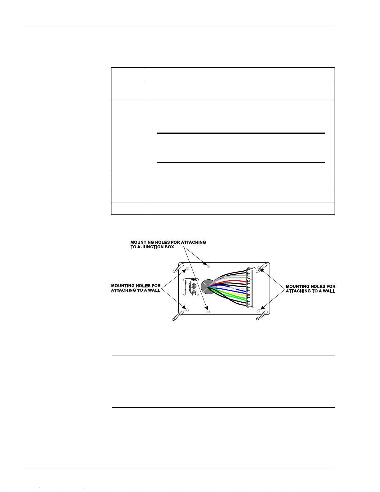
Use the following procedure and refer to Figure 1, as necessary to mount the
baseplate.
StepProcedure
1Turn off all power to the HVAC equipment before mounting the
baseplate.
2Position the baseplate against the mounting surface and mark the
surface to show the location of the four screw holes in the corners
of the baseplate.
NOTE!To mount the baseplate to a junction box, use the
two holes located directly above and below the
large hole through which the wires pass.
3Drill holes in the locations marked on the mounting surface and
insert hollow-wall anchors (and insulation, if necessary).
4Position the baseplate over the screws.
5Tighten the screws to secure the baseplate.
Supplying the ETM-2040
with Power
Connect the ETM-2040 to a suitable 24-VDC power supply. Connect the
positive (+) and negative (–) power terminals to the appropriate wire as indicated
in Table 1.
2DOC. #560075000 2/12/01
ETM-2040 Installation Instructions
Figure 1.Mounting the baseplate

Wiring the ETM-2040
Control Outputs
Use the wire nuts provided and the wiring scheme outlined in Table 1 to connect
the ETM-2040 baseplate wires to the HVAC control/interface equipment.
CAUTION!Make sure the wiring is connected properly to
prevent permanent damage to the system.
Table 1. ETM-2040 Wiring Scheme
PIN NUMBER/COLORFUNCTION
1 White/BlueHeat Stage 2
2 WhiteHeat Stage 1
3 White/BlackModule Communication (–)
4 White/RedModule Communication (+)
5 Dark BlueHeat/Cool Return (Transformer Power)
6 YellowCool Stage 1
7 OrangeCool Stage 2
8 White/Black/GreenModule Power (–)
9 White/Black/RedModule Power (+), +24-VDC
10 Light BlueHeating Stage 3 or Dampers
11 GreenFan
12 BrownFan Status Input
13 White/BrownFilter Status Input
14 Polarizing Key
15 BlackStatus Return
16 BlackStatus Return
17 BlackModule Communication (Shield)
18 VioletTemperature Sensor (+)
19 GrayTemperature Sensor (–)
DOC. #560075000 2/12/013
ETM-2040 Installation Instructions
Temperature Sensor
The distance between the ETM and the temperature sensor can be up to 1000
feet. Refer to the sensor’s installation instructions for mounting and complete
wiring details.
StepProcedure
1Mount the remote temperature sensor in the zone being controlled
or in the supply air of the HVAC unit.
2Run a shielded 2-conductor cable (Belden 8761, Novar
WIR-1010, or equivalent) from the sensor to the baseplate.
3Connect the plus (+) lead to the violet wire.
4Connect the minus (–) lead to the gray wire at the ETM-2040.
Fan Status
Use a shielded 2-conductor cable (Belden 8761, Novar WIR-1010, or equivalent)
to connect the fan status switch to the ETM.
StepProcedure
1Connect one lead from the fan status switch to the ETM’s brown
wire.
2Connect the other lead from the fan status switch to one of the
ETM’s black wires (see Table 1, Status Return).
The fan status switch contact is open when the fan is off and closed when the fan
is on.
Dirty Filter Switch
Use a shielded 2-conductor cable (Belden 8761, Novar WIR-1010, or equivalent)
to connect the filter status switch to the ETM.
StepProcedure
1Connect one lead from the filter status switch to the ETM’s
white/brown wire.
2Connect the other lead from the filter status switch to one of the
ETM’s black wires (see Table 1, Status Return).
The filter status switch contact is closed when the filter is dirty.
4DOC. #560075000 2/12/01
ETM-2040 Installation Instructions

Communications Network
Use a shielded 2-conductor cable (Belden 8761, Novar WIR-1010, or equivalent)
to connect communications between the ETM and the network communication
terminals of the executive module. Use the following procedure to make the
connections at the ETM.
StepProcedure
1Connect the plus (+) lead to the white/red wire.
2Connect the minus (–) lead to the white/black wire.
3Connect the shield to the black wire (see Table 1, Module
Communication Shield).
Testing the Wiring
Before installing the ETM-2040 electronics module, use an ETM Interface
Analyzer and the ETM-2020 adapter cable to test the baseplate for correct
wiring. The analyzer tests for module power and allows manual cycling of the
ETM outputs. Instructions are provided with the analyzer and the adapter cable.
Installing the ETM-2040
Electronics
NOTE!Before the electronics are installed, make sure that the
baseplate has been properly installed.
A hardware kit to be used during installation is shipped with the electronics. It
contains four screws and a hex key.
Setting the Module’s Address
Locate the address switches on the rear of the module (see Figure 2). Each
module requires a unique address for the executive module to identify it.
Addresses are assigned during system programming. Use the system
configuration to find the address of the ETM being installed.
DOC. #560075000 2/12/015
ETM-2040 Installation Instructions
Figure 2.ETM address switch and connector

Set the switches on the back of the electronics with the correct address from 00 to
63 (see Figure 3).
NOTE!Address 00 may notbe used by the ETM when operating
on an EC. (The IOM section of the EC uses address 00).
Record the settings on the module address switch label on the back of the ETM
electronics and on the label provided with the ETM baseplate hardware kit.
Apply the baseplate label to the ETM baseplate as shown in Figure 2.
The EP/2 executive module is designed to accept module addresses from 00 to
127 for any type of LOGIC ONE module. The EP/2 would require a Network
Expander to communicate with addresses 64 through 127. Only unitary
controllers can be connected to the Network Expander. Addresses 64 through
127 are set using the same sequence of settings shown in Figure 3, beginning
with address setting 64 being the same as address setting 00, etc. (The Network
Expander Module Installation Instructions [Doc. #560092000] provide more
information about setting the addresses from 64 through 127.) When connecting
additional modules to the EP/2, do not exceed the their 128-input or 128-output
limits.
6DOC. #560075000 2/12/01
ETM-2040 Installation Instructions
Figure 3.Setting the module address
Mounting the ETM
Electronics
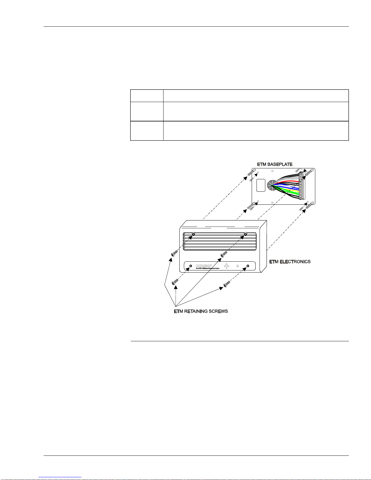
Use the following procedure and refer to Figure 4 to mount the ETM electronics
on the baseplate. Make sure the connector on the rear of the ETM electronics fits
properly into the pigtail wiring connector on the baseplate.
StepProcedure
1Align the module over the mounting posts and press onto the
baseplate connector as shown in Figure 4.
2Use the screws and hex key provided in the hardware kit to secure
the module to the posts.
Checking Installation
Turn on power to the ETM-2040. Make sure that power to the HVAC equipment
and its control circuitry is on. If the executiv e module is operating properly, the
ETM begins to control the HVAC equipment in about 3 minutes (after
performing a self-diagnostic check and establishing communications with the
executive module).
§Output Status Indicators
There are six output status indicators (inside the ETM case and visible through
the front grill) that show the status of each output. The indicator is lit when
the corresponding output is on.
DOC. #560075000 2/12/017
ETM-2040 Installation Instructions
Figure 4.ETM electronics installation
§Override Switch Input
The ETM-2040 has a built-in timed override switch. To test the switch for
proper function, press the switch when the schedule status indicator is off (if
set to “active” in the software). The schedule status indicator exhibits a steady
flash that stops when the override period ends. On a call for heating or
cooling, the ETM’s output indicators should show a change in status.
To cancel the timed override, press the button a second time. The schedule
status indicator stops flashing when the timed override is canceled.
§Schedule Status Indicator
Observe the flashing pattern of the schedule status indicator to verify proper
communications between the ETM and the executive module.
—The schedule status indicator should be on during scheduled on periods.
—The schedule status indicator should be off during scheduled off periods.
It flashes on or off regularly when communicating with the executive module,
depending upon the schedule status (off or on). When a scheduled timed
override has been implemented, the schedule status indicator flashes steadily
and stops when the override period ends. The steady flash is broken when the
ETM is communicating with the executive module.
§Checking from the EP/2 or EC
If any faults or malfunctions still exist, they are picked up by the executive
module and announced by alarm messages.
Monitor the executive module display during the test procedures. The ETM’s
setpoints can be altered from the executive module keypad and the status
display monitored for proper equipment response from the keypad.
Model and Part Numbers
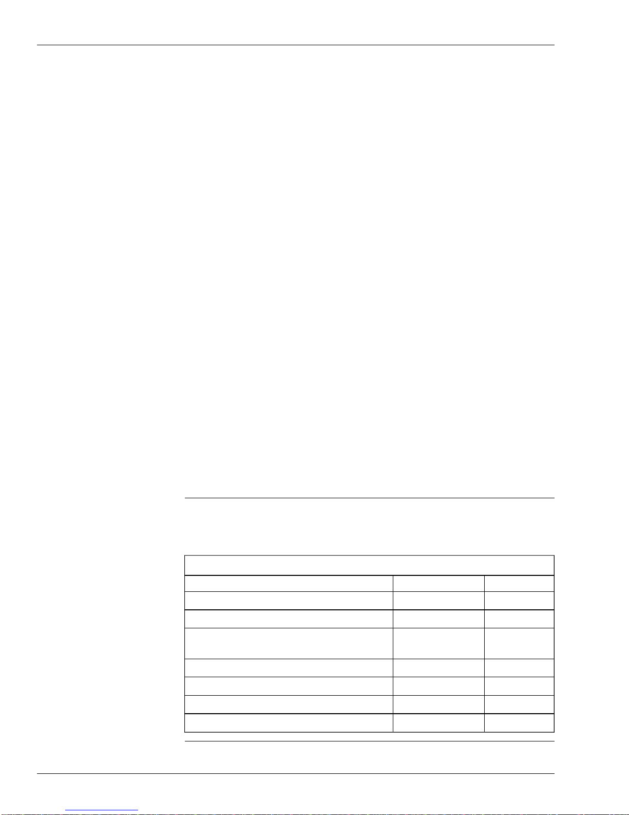
Use the part numbers provided in Table 2 to order the necessary Novar parts.
Table 2. Novar ETM-2040 Model Numbers
PRODUCTMODEL NO.PART NO.
ETM-2040 BaseplateETM-2040-BPL705100000
ETM-2040 Electronics ETM-2040729041000
Two-conductor, shielded cable (Belden
8761equivalent)WIR-1010709001000
Module Interface AnalyzerMOD-EIA706000000
Adapter CableEIAC706065000
Wall-Mount Temperature SensorWTS-10712003000
Futura Temperature SensorFTS-1732203000
8DOC. #560075000 2/12/01
ETM-2040 Installation Instructions
Table of contents
Other Novar Control Unit manuals

Popular Control Unit manuals by other brands


EDS
EDS SPM-010 user guide

PRESONUS
PRESONUS CENTRAL STATION user manual

AVer
AVer NV series user manual

National Instruments
National Instruments 9221 Getting started guide

Texas Instruments
Texas Instruments LM5122EVM-2PH user guide

Deep Sea Electronics Plc
Deep Sea Electronics Plc DSE6120 MKII Operator's manual