EDS SPM-010 User manual

SPM-010 Sump Pump Monitor and Control Unit EDSPN: 2052102004
© Copyright 2022 Electronic Design Service, LLC All Rights Reserved Page 1
Electronic Design Service
SPM-010 Sump Pump Monitor/Control Unit
User Guide

SPM-010 Sump Pump Monitor and Control Unit EDSPN: 2052102004
© Copyright 2022 Electronic Design Service, LLC All Rights Reserved Page 2
Revision History
The Table below displays the revision history for the chapters in this User Guide
Date
Version
Change Made
April 24,
2022
1.0
Original release
Contact Us
For the most up-to-date information about the Electronic Design Service products, go to the Electronic
Design Service website at www.eldesignservice.com.
Technical Support:
Phone: +1 319 553-6080
www.eldesignservice.com

SPM-010 Sump Pump Monitor and Control Unit EDSPN: 2052102004
© Copyright 2022 Electronic Design Service, LLC All Rights Reserved Page 3
Contents
Revision History .......................................................................................................................................... 2
Contact Us .................................................................................................................................................. 2
About SPM-010 Sump Pump Monitor/Control Unit ................................................................................... 5
Specifications.......................................................................................................................................... 7
Inside Box................................................................................................................................................ 8
Components and Applications ................................................................................................................ 9
Connections and Connector Panel........................................................................................................ 11
Installation and Adjustment...................................................................................................................... 12
WS Sensor Installation .......................................................................................................................... 12
WS-010 (without SIP) and SPM-010 Installation Instruction............................................................. 13
WS-010 (with SIP) and SPM-010 Installation Instruction .................................................................. 15
Resistive Sensor (KUS / SSS), SPM-010 and SSR-CU Installation............................................................ 16
KUS SSS Resistive Sensor and SPM-010 Installation Instruction........................................................ 18
SPM-010 Installation............................................................................................................................. 19
Installation Warning.............................................................................................................................. 19
Operation.................................................................................................................................................. 20
SPM-010 Dummy Cell Installation and Serial Number Location............................................................ 20
SPM-010 Front Panel ............................................................................................................................ 21
SPM-010 iOS Application Installation and Operation............................................................................ 21
Installation ........................................................................................................................................ 21
iOS Application Screenshot............................................................................................................... 24
Start and Operation Conditions with Messaging .............................................................................. 25
Battery Warning........................................................................................................................................ 28
Warranty................................................................................................................................................... 29
Troubleshooting........................................................................................................................................ 30
Support..................................................................................................................................................... 30
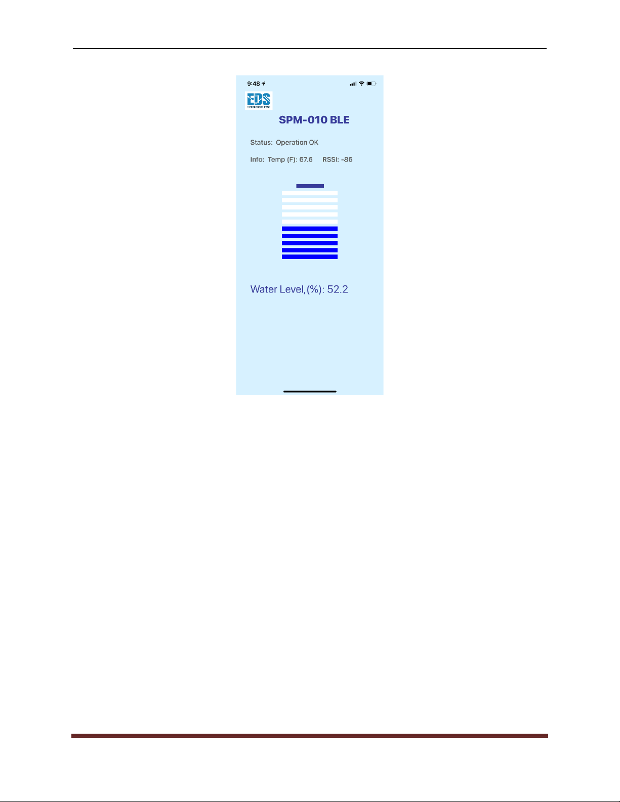
Figure 1 Normal Operation Screen Example............................................................................................... 6
Figure 2 Inside Home Application only ....................................................................................................... 9
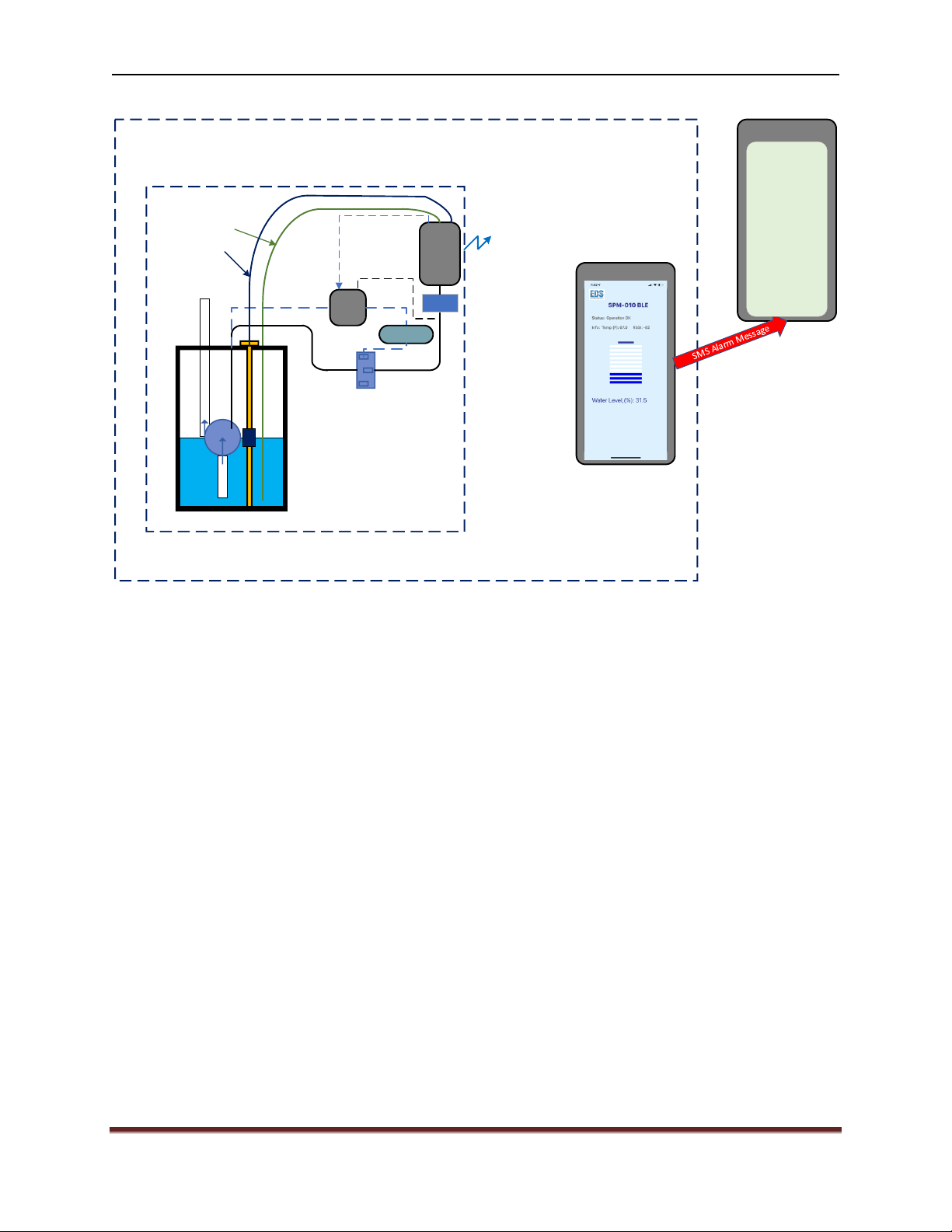
Figure 3 Inside and Outside Home Application......................................................................................... 10
Figure 4 Connection Diagrams SPM-010 v4 (top) and SPM-010 v5 (bottom) ........................................... 11

SPM-010 Sump Pump Monitor and Control Unit EDSPN: 2052102004
© Copyright 2022 Electronic Design Service, LLC All Rights Reserved Page 4
Figure 5 WS-010 Sensor (without Sensor Installation Pipe (SIP)) and SPM-010 Installation diagram for
Monitoring Operation Mode .................................................................................................................... 13
Figure 6 WS-010 Sensor with SIP and SPM-010 Installation Diagram for Monitoring Operation Mode ... 14
Figure 7 Resistive sensor and SPM-010 Installation Diagram for Monitoring Operation .......................... 16
Figure 8 Resistive sensor, SPM-010 and SSR-CU Installation Diagram for Monitoring and Control
Operation Mode ....................................................................................................................................... 17
Figure 9 Resistive sensor, SPM-010 and SSR-CU Installation Diagram for Monitoring and Control
Operation Mode with Redundant Pump................................................................................................... 18
Figure 10 Silicon Cover.............................................................................................................................. 20
Figure 11 Dummy Cell Installation and Serial Number Location ............................................................... 20
Figure 12 SPM-010 Front Panel................................................................................................................. 21
Figure 13 Activation Message................................................................................................................... 22
Figure 14 Message Phone number at start ............................................................................................... 23
Figure 15 iOS Application Screenshot ....................................................................................................... 24
Figure 16 Power Loss and Power Messages Screenshots ......................................................................... 25
Figure 17 Water Level Alarm and Message Screenshots .......................................................................... 26
Figure 18 Power Loss and Water Alarm message ..................................................................................... 26
Figure 19 Normal operation with battery charging screenshot ................................................................ 27
Figure 20 Low Temperature and Temperature Normal Messages............................................................ 27

SPM-010 Sump Pump Monitor and Control Unit EDSPN: 2052102004
© Copyright 2022 Electronic Design Service, LLC All Rights Reserved Page 5
About SPM-010 Sump Pump Monitor/Control Unit
SPM-010 is a Bluetooth Low Energy Monitor/Control Unit (device). The SPM-010 communicates with
smartphone or tablets. This combination forms the SPM-010 Monitor / Control System (SPM-010 or
system). The system constantly informs home owner about sump water level, power condition of sump
pump and temperature near the sump. Also, system provides efficient control of sump pump and
messaging service in critical conditions.
The advantages of SPM-010 are:
-Independence from home WiFi and internet stability
-Indication of the actual water level, power status and temperature at any given time
-Effective pump control
-Ability to operate in case of power outage
SPM-010 unit monitors
Water level (with adjustable alarm level), air temperature device operational status and device battery
charging status. All these parameters are visible on smartphone or tablet at any time (see Figure 1 as
normal operation example screen). SPM-010 has an internal rechargeable battery, produces audio alarm
and can operate independently from smartphone or tablet.
Sump Pump control function is optional and requires to use SSR-CU module.

SPM-010 Sump Pump Monitor and Control Unit EDSPN: 2052102004
© Copyright 2022 Electronic Design Service, LLC All Rights Reserved Page 6
Figure 1 Normal Operation Screen Example

SPM-010 Sump Pump Monitor and Control Unit EDSPN: 2052102004
© Copyright 2022 Electronic Design Service, LLC All Rights Reserved Page 7
Specifications
Operating Temperature: 32°F 110°F (0° 45°C)
Operating Humidity: 0 95%, non-condensing
Temperature Accuracy: ±1.8°F (1°C )
Water Level Wire Sensor (WS-010) Wire Length: (1.85m)
Water Level (WS-010) Range: 0 - (0.95m)
Water Leve (WS-010) Accuracy: ± 2%
WS-010 Sensor Calibration Range: 0 100% (any range from 0.3m) to 0.95m))
WS-010 Sensor Input: two dry contacts
Resistive Water Level Sensor: 240 33 Ohms (240 Ohms at empty, 33 Ohms at full)
Resistive Sensor Level Transferring Characteristics: KUS SSS-24 sensor (two linear branches with break
point at 21.3% length)
Resistive Sensor Resolution Range (KUS SSS sensor): 21m)
Resistive Sensor Input: Two dry contacts
Input Power: 5VDC, 500mA
Battery: 3.7V Lithium Ion 750mAH (KLARUS LIR 14500 protected battery)
Internal Alarm: 85dB
Bluetooth: 2.4-GHz RF Transceiver Compatible with Bluetooth low energy (BLE) 4.2 Specification
Antenna: Integrated Antenna
FCC Compliance: FCC CFR47, Part 15 and ARIB STD-T-66
Pump Control Interface: two pins LED control with 3mA current maximum (Solid State Relay Control)
SPM-010 Application SW: iOS 14.5 or newer version devices

SPM-010 Sump Pump Monitor and Control Unit EDSPN: 2052102004
© Copyright 2022 Electronic Design Service, LLC All Rights Reserved Page 8
Inside Box
1. SPM-010 device
2. WS-010 water level sensor
3. AA size Dummy Cell (needs to be installed in SPM-010 in empty battery slot)
4. 120VAC / +5VDC Power adapter

SPM-010 Sump Pump Monitor and Control Unit EDSPN: 2052102004
© Copyright 2022 Electronic Design Service, LLC All Rights Reserved Page 9
Components and Applications
iPhone/iPAD
SPM-010
BLE
(Battery
included)
House Bluetooth Zone
SUMP PUMP AREA
Inside House Sump Pump Monitoring and Control
AC Out
Real Time Parameters:
- True Water Level
- Sump Pump Power and Operation Statuses
- Air Temperature
Real Time Indication:
- True Water Level
- Power and Operation Statuses
- Air Temperature
- ALARM
-ALARM Sound
SPM-010 – Sump Pump Monitor
and Control:
- Local Alarm Sound
- Rechargeable Battery
- Pump Control (through SPM-CU,
Optional)
- Full System Monitoring with
Bluetooth communication
Wire Level Sensor
Or
KUS SSS/SSL Sender Sensor
SSR-CU
SSR-CU -
Optional
PWR
Backup
Pump Control
Power
Adapter
Figure 2 Inside Home Application only

SPM-010 Sump Pump Monitor and Control Unit EDSPN: 2052102004
© Copyright 2022 Electronic Design Service, LLC All Rights Reserved Page 10
iPhone/iPAD
House Bluetooth Zone
Inside/Outside House Sump Pump Monitoring and Control
Real Time Parameters:
- True Water Level
- Sump Pump Power and Operation Statuses
- Air Temperature
Real Time Indication:
- True Water Level
- Power and Operation Statuses
- Air Temperature
- ALARM
-ALARM Sound
iPhone/iPAD
SMS:
- Power Status Alarm
- Water Level Alarm
with true water level
parameter
- Air Temperature
less than 45F
SPM-010
BLE
(Battery
included)
SUMP PUMP AREA
AC Out
SPM-010 – Sump Pump Monitor
and Control:
- Local Alarm Sound
- Rechargeable Battery
- Pump Control (through SPM-CU,
Optional)
- Full System Monitoring with
Bluetooth communication
Wire Level Sensor
Or
KUS SSS/SSL Sender Sensor
SSR-CU
SSR-CU -
Optional
PWR
Backup
Pump Control
Power
Adapter
Figure 3 Inside and Outside Home Application

SPM-010 Sump Pump Monitor and Control Unit EDSPN: 2052102004
© Copyright 2022 Electronic Design Service, LLC All Rights Reserved Page 11
Connections and Connector Panel
SPM-010
PUMP_CTRL
GND
V+
V-
WS_SIG
WS_GND
PUMP_3V3
Top View
5V_PWR
V+
V-
Resistive Sensor
240 Ohms to 33 Ohms
120AC to 5VDC
0.5A Adapter
GND
WS-010: Lw=1.85m (72.8"), Lopw=0.95m (37")
+3.3VDC
To SPM_CU (Solid State Relay)
(3.3V, 7mA)
KUS SSS/SSL sensor
Notes:
1. Resistive Sensor can be used for monitoring and control function
2. WS-010 sensor can be used for monitoring function only
SPM-010
PUMP_CTRL
PUMP_3V3
V+
V-
WS_SIG
WS_GND
FLOAT_SWITCH
Top View
5V_PWR
V+
V-
Resistive Sensor
240 Ohms to 33 Ohms
120AC to 5VDC
0.5A Adapter
GND
WS-010: Lw=1.85m (72.8"), Lopw=0.95m (37")
+3.3VDC
To SPM_CU (Solid State Relay)
(3.3V, 7mA)
KUS SSS/SSL sensor
Notes:
1. Resistive Sensor can be used for monitoring and control function
2. WS-010 sensor can be used for monitoring function only
Figure 4 Connection Diagrams SPM-010 v4 (top) and SPM-010 v5 (bottom)

SPM-010 Sump Pump Monitor and Control Unit EDSPN: 2052102004
© Copyright 2022 Electronic Design Service, LLC All Rights Reserved Page 12
Installation and Adjustment
Note: In case default calibration data does not match the actual depth of the sump, the WS-010 Water
level sensor needs to be calibrated in accordance with procedure described in WS-010 Sensor
Calibration Instruction.
WS Sensor Installation
Wire Sensor can be installed by two ways. First way, it can be attached to sump pump discharge pipe. It
allows to avoid WS-010 floating and blocking pump sensor. See Figure 5 for this connection method.
The WS-010 is installed vertically on the PVC discharge pipe of the sump pump. The sensor wire attaches
to the PVC pipe with zip ties. Place the sealed end of the sensor wire as far down the discharge pipe as
possible. Care must be taken to secure the sensor wire to the discharge pipe to avoid it being sucked
or metal piping as this can result in measurement inaccuracy.
NOTE: DO NOT CUT OR INCREASE WIRE SENSOR LENGTH!!!!!

SPM-010 Sump Pump Monitor and Control Unit EDSPN: 2052102004
© Copyright 2022 Electronic Design Service, LLC All Rights Reserved Page 13
Bottom
AC Adapter
WSU050-1500-R
5VDC
L% - 100%
Ltop = 2" - 3"
(51mm 76mm))
Lsump
Sump Pump
Sump Pump
Switch Sump Pump Cover
Cable Zip Ties
SPM-
010
BLE
Discharge Pipe
Bundling Strap
Switch
Connector
Figure 5 WS-010 Sensor (without Sensor Installation Pipe (SIP)) and SPM-010 Installation diagram for Monitoring Operation
Mode
WS-010 (without SIP) and SPM-010 Installation Instruction
1. Install WS-010 as shown on Figure 5 along of discharge pipe by using Cable Zip Ties.
Notes:
a) Sealed end of WS-010
b) Do not strongly cable tie the sensor wire around discharge pipe. Sensor wire shall be
loosely fixed to the pipe.
2. Seal the sump cover area around of WS-010 installation by using any plumbing caulk. if it is
needed.
3. Install SPM-010 in accordance with SPM-010 Installation section.
4. Connect system in accordance with Figure 5 and Figure 4.
NOTE: DO NOT CUT OR INCREASE WIRE SENSOR LENGTH!!!!!

SPM-010 Sump Pump Monitor and Control Unit EDSPN: 2052102004
© Copyright 2022 Electronic Design Service, LLC All Rights Reserved Page 14
The second way of installation is to use plastic pipe (sensor installation pipe - SIP). The
hole (equal to external PEX pipe diameter) should be drilled in sump cover. This hole shall be far from
sump pump switch and pump. The sensor wire is installed inside of the SIP. The SIP needs to be cut
approximately -2See Figure 6 installation diagram.
Bottom
SPM-
010
BLE
AC Adapter
WSU050-1500-R
5VDC
¼PEX Pipe (SIP)
Pipe Edge
L% - 100%
Ltop = 2" - 3"
(51mm 76mm))
Lsump
Sump Pump
Sump Pump
Switch Sump Pump Cover
WS-010
Discharge Pipe
Bundling Strap
Switch
Connector
Figure 6 WS-010 Sensor with SIP and SPM-010 Installation Diagram for Monitoring Operation Mode

SPM-010 Sump Pump Monitor and Control Unit EDSPN: 2052102004
© Copyright 2022 Electronic Design Service, LLC All Rights Reserved Page 15
WS-010 (with SIP) and SPM-010 Installation Instruction
1. Find the SIP installation location. The location shall meet the following criteria:
a) Be far enough from sump pump switch and pump
b) Be installed at deepest area
2. Measure external diameter (Dext) of SIP and drill mounting hole (hole diameter is Dext) in the
chosen cover installation area.
3. Measure the Lsump (see Figure 6) and keep record.
4. Cut SIP bottom edge as shown on Figure 6.
5. Cut SIP to adjust length approximately 12 (L_SIP = Lsump + Hcover +
. Where Hcover is thickness of cover.
6. Install SIP into the mounting hole in the way when cut edge is connected to bottom of sump and
seal the sump cover area of installation hole by using any plumbing caulk.
7. Install WS-010 sensor inside of SIP until lightly touching the bottom.
8. Install SPM-010 in accordance with SPM-010 Installation section.
9. Connect system in accordance with Figure 6 and Figure 4.
NOTE: DO NOT CUT OR INCREASE WIRE SENSOR LENGTH!

SPM-010 Sump Pump Monitor and Control Unit EDSPN: 2052102004
© Copyright 2022 Electronic Design Service, LLC All Rights Reserved Page 16
Resistive Sensor (KUS / SSS), SPM-010 and SSR-CU Installation
The SPM-010 with KUS/SSS resistive sensor can be used in multiple configurations. It can be used for
monitoring, monitoring and pump control and for monitoring and redundant (emergency) pump control.
All installation cases are shown in Figure 7, Figure 8 and Figure 9. Use Figure 4 SPM-010 connection
diagram for SPM-010 connection. Note: The SSR-CU unit (or relay device with similar electrical
characteristics) needs to be used to implement pump control function.
The resistive sensor installation method is the same for all system installation variants. The hole (equal
to sensor float diameter) should be drilled in sump cover. Sensor shall be installed far from sump pump
switch and pump.
Bottom
AC Adapter
WSU050-1500-R
KUS/SSS
Resistive Sensor
L% - 100%
Ltop = 2" - 3"
(51mm 76mm))
Lsump
Sump Pump
Sump Pump
Switch Sump Pump Cover
Discharge Pipe
Bundling Strap
Sensor Float
SPM-
010
BLE
5VDC
Switch
Connector
Figure 7 Resistive sensor and SPM-010 Installation Diagram for Monitoring Operation

SPM-010 Sump Pump Monitor and Control Unit EDSPN: 2052102004
© Copyright 2022 Electronic Design Service, LLC All Rights Reserved Page 17
Bottom
AC Adapter
WSU050-1500-R
KUS/SSS
Resistive Sensor
L% - 100%
Ltop = 2" - 3"
(51mm 76mm))
Lsump
Sump Pump
Sump Pump
Switch Sump Pump Cover
Discharge Pipe
Bundling Strap
Sensor Float
SPM-
010
BLE
5VDC
SSR-CU
Figure 8 Resistive sensor, SPM-010 and SSR-CU Installation Diagram for Monitoring and Control Operation Mode

SPM-010 Sump Pump Monitor and Control Unit EDSPN: 2052102004
© Copyright 2022 Electronic Design Service, LLC All Rights Reserved Page 18
Bottom
AC Adapter
WSU050-1500-R
KUS/SSS
Resistive Sensor
L% - 100%
Ltop = 2" - 3"
(51mm 76mm)
Lsump
Original Sump Pump
Sump Pump
Switch
Sump Pump Cover
Discharge Pipes
Bundling Strap
Sensor Float
SPM-
010
BLE
5VDC
SSR-CU
Power Backup
Redundant Sump Pump
Switch
Connector
Figure 9 Resistive sensor, SPM-010 and SSR-CU Installation Diagram for Monitoring and Control Operation Mode with
Redundant Pump
KUS SSS Resistive Sensor and SPM-010 Installation Instruction
1. Measure the depth of sump (Lsump - Figure 7) and order sensor length a one-step less or equal
to Lsump value.
2. Find the sensor location. The location shall meet the following criteria:
c) Be far enough from sump pump switch and pump
d) Be installed for deepest area
3. Measure external diameter (Dext) of sensor float and drill mounting hole (hole diameter is Dext)
in the chosen cover installation area.
4. Install sensor into the mounting hole and seal the area of installation plate by using any
plumbing caulk.
Note: Do not use screws for mounting. It will be enough of using plumbing caulk.
5. Install SPM-010 in accordance with SPM-010 Installation section.
6. Connect system in accordance with Figure 7 and Figure 4.

SPM-010 Sump Pump Monitor and Control Unit EDSPN: 2052102004
© Copyright 2022 Electronic Design Service, LLC All Rights Reserved Page 19
SPM-010 Installation
The SPM-010 installation example is shown in Figure 5, Figure 6 and Figure 7.
Velcro ONE-WRAP Roll or similar can be used for SPM-010 mounting on discharge pipe.
Wire connections shall be performed in accordance with Figure 4 for sensor type which plan to be used.
Installation Warning
Disconnect all sump pump circuit breakers before beginning work. If you are unfamiliar or
uncomfortable, please contact a licensed electrician or plumber to perform the installation.

SPM-010 Sump Pump Monitor and Control Unit EDSPN: 2052102004
© Copyright 2022 Electronic Design Service, LLC All Rights Reserved Page 20
Operation
SPM-010 Dummy Cell Installation and Serial Number Location
The SPM-010 is shipped with uninstalled Dummy Cell.
Serial Number is located on back side label (see Figure 11).
The Dummy Cell shall be installed before start of operation:
1. Remove silicon cover (see Figure 10)
2. Open battery cover and install Dummy Cell (see Figure 11)
3. Close battery cover and install silicone cover.
Figure 10 Silicon Cover
Figure 11 Dummy Cell Installation and Serial Number Location
Table of contents
Popular Control Unit manuals by other brands

Dormakaba
Dormakaba MFC installation instructions

Zapi
Zapi ZAPIMOS H2B user manual

Eaton
Eaton CEAG DLS/3PH-BUS-Module-inverse Mounting and operating instructions

NXP Semiconductors
NXP Semiconductors A3M38SL039 manual

Allen-Bradley
Allen-Bradley XM-124 user manual

extronics
extronics ISOLATE 100: ISOLATE 100M operating manual