Novasub SCC-2DRVL-DVR User manual

Manual SCC-2DRVL-DVR Gen2
www.novasub.com
Rev 5
1
of
47
Manufactured by Seascape.nl
OPERATIONS MANUAL
Divers Communication Radio with integrated 0.4” daylight monitor
and Full PAL DVR
SCC-2DRVL-DVR
Gen2
(Manufactured after 07-20 ) / OSD- &2 overlay
S
urface
C
ontrol
C
ase
2 D
ivers
R
adio
with
V
ideo
, L
ight control and
D
igital
V
ideo
R
ecorder

Manual SCC-2DRVL-DVR Gen2
www.novasub.com
Rev 5
2
of
47
Manufactured by Seascape.nl
Index
1
General description ............................................................................................................ 4
2
General functions ............................................................................................................... 4
3
Quick startup ...................................................................................................................... 8
4
Charging the system ......................................................................................................... 10
5
Video configuration.......................................................................................................... 11
5.1
Setting for Video transmission type .......................................................................... 11
5.1.1
Set for video over Coax cable ............................................................................ 11
5.1.2
Set for video over twisted pair. .......................................................................... 12
5.2
Video compensating settings for cable length over TSP........................................... 12
6
Diver audio....................................................................................................................... 14
6.1
Diver audio adjust...................................................................................................... 14
7
External Speaker .............................................................................................................. 15
8
Headset / Mic ................................................................................................................... 15
9
BOBOX (optional) ........................................................................................................... 16
10
Duplex 4 wire communication (optional) ........................................................................ 16
11
Third party camera connection......................................................................................... 16
12
Sensor data input on Video overlay (Optional)................................................................ 17
12.1
USD-1 Diver Depth sensor (D).............................................................................. 17
12.2
Thickness Gauge (T).............................................................................................. 17
12.3
CP probe (CP) ........................................................................................................ 18
12.4
Data output............................................................................................................. 18
12.4.1
Data outputs........................................................................................................ 18
12.5
Sensor connections................................................................................................. 18
13
Connections...................................................................................................................... 19
13.1
Standard SCC with OSD-1 .................................................................................... 19
13.2
Optional SCC with OSD-2..................................................................................... 21
14
Video Overlay Instructions OSD-1 .................................................................................. 23
15
Video overlay instructions OSD-2 ................................................................................... 24
16
DVR panel:....................................................................................................................... 26
16.1
Quick DVR guide .................................................................................................. 27
16.1.1
Recording ........................................................................................................... 27
16.1.2
Pause recording .................................................................................................. 27
16.1.3
Stop recording .................................................................................................... 27
16.1.4
Playback recorded files ...................................................................................... 27
16.1.5
Copy files to USB Disk (USB Memory stick) ................................................... 28
16.1.6
Copy files to PC ................................................................................................. 28
17
Operating instructions DVR............................................................................................. 30
17.1
The Remote Control............................................................................................... 30
17.1.1
Function.............................................................................................................. 30
17.2
Getting Started ....................................................................................................... 31
17.3
Format Hard Disc................................................................................................... 32
17.4
AV In ..................................................................................................................... 33
17.5
Instant Record ........................................................................................................ 33
17.6
Browse Recordings List......................................................................................... 33
17.7
Timer Record ......................................................................................................... 33
17.8
Creating a New Schedule....................................................................................... 34
17.9
Editing Schedules................................................................................................... 34
17.10
Deleting Schedules................................................................................................. 34
17.11
Viewing Schedule Status Viewing Schedule Status .............................................. 35

Manual SCC-2DRVL-DVR Gen2
www.novasub.com
Rev 5
3
of
47
Manufactured by Seascape.nl
17.12
Viewing Recording History ................................................................................... 35
17.13
Timeshift Function................................................................................................. 35
17.14
Browser .................................................................................................................. 35
17.15
Browser Menu........................................................................................................ 35
17.16
Browsing All.......................................................................................................... 36
17.17
Playback Movie ..................................................................................................... 36
17.18
Playlist function ..................................................................................................... 36
17.19
Add files into Playlist............................................................................................. 37
17.20
View files in Playlist.............................................................................................. 37
17.21
Delete files in Playlist ............................................................................................ 37
17.22
File Copy................................................................................................................ 37
17.23
Select Source Device ............................................................................................. 37
17.24
Select Destination Device ...................................................................................... 37
17.25
Select copy files or folders..................................................................................... 38
17.26
Select the folders of Destination ............................................................................ 38
17.27
Copy Status ............................................................................................................ 38
17.28
Setup Menu ............................................................................................................ 39
17.29
Changing Audio Settings ....................................................................................... 39
17.29.1
Night Mode..................................................................................................... 39
17.29.2
Digital Output ................................................................................................. 39
17.30
Changing Video Settings ....................................................................................... 40
17.30.1
Aspect Ratio ................................................................................................... 40
17.30.2
Brightness ....................................................................................................... 40
17.30.3
Contrast........................................................................................................... 40
17.30.4
TV System ...................................................................................................... 40
17.31
Changing Record Settings...................................................................................... 40
17.31.1
Quality ............................................................................................................ 41
17.31.2
Automatic timeshift ........................................................................................ 41
17.31.3
Record Device ................................................................................................ 41
17.32
Changing Network Settings ................................................................................... 41
17.33
Changing System Settings ..................................................................................... 41
17.33.1
Menu Language .............................................................................................. 42
17.33.2
Text Encoding................................................................................................. 42
17.33.3
Time................................................................................................................ 42
17.33.4
HDD Format ................................................................................................... 43
17.33.5
Restore Default ............................................................................................... 43
17.34
Changing Photo Settings........................................................................................ 43
17.34.1
Slide Show Time ............................................................................................ 43
17.34.2
Transition Effect ............................................................................................. 44
17.34.3
Background Music.......................................................................................... 44
18
QuickStart Chart............................................................................................................... 45
19
Appendix 1 Umbilical configurations .............................................................................. 47

Manual SCC-2DRVL-DVR Gen2
www.novasub.com
Rev 5
4
of
47
Manufactured by Seascape.nl
General description
The SCB-2DRVL-DVR is a 2 diver radio communication unit with integrated video and LED
light controller with HD recorder and 10,4” Daylight TFT monitor.
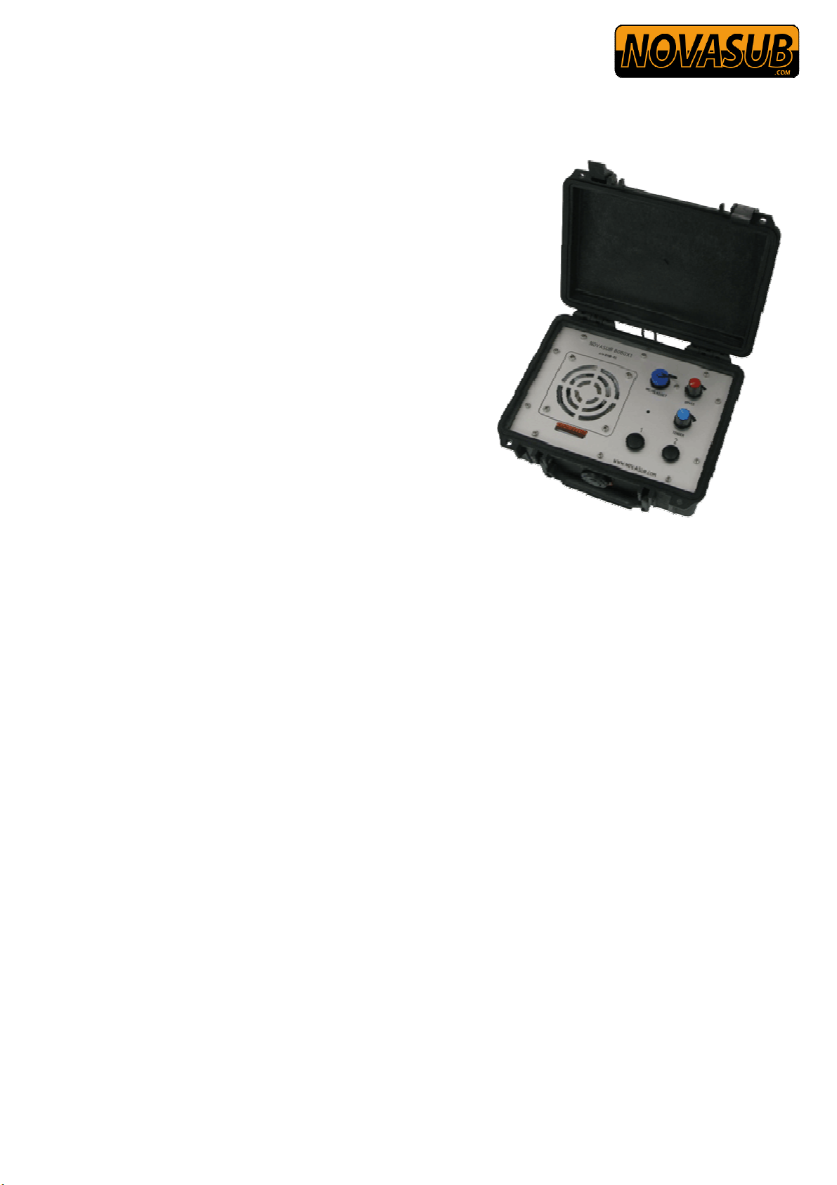
The radio is built in a ruggedized flight case of which the Lid can be removed for easy setup
on a table.
Two divers can be connected and operated at the same time. For each diver the audio volume
can be adjusted for surface and diver. Each diver LED light can be regulated for 0-100%.
Intensity. The diver communication is based on a simplex 2 wire communication. This means
that the divers is always listened out at the surface and the operator needs to press the PTT
button to talk to the diver. Each diver has its own PTT.
The system needs to be powered by 100- 240 vac and has a built in uninterruptable power
supply (UPS) function. This is realized with a battery system and an automatic battery
charger. The SCC will also operate for approx. 1 hour on the internal UPS.
The status of the batteries is indicated with 3 LED’s.
An optional external speaker is controlled by an independent amplifier.
Camera and light of each diver can be switched on and off.
The built in video camera controller can be set for video signal over normal twisted pair cable
or coaxial cable. The video signal can be external adjusted to corresponding cable length.
The maximum cable length without loss of video signal is 400 m.
The built in DVR can record one diver video (selectable) and records audio of both divers and
surface operator. The DVR records in Full PAL resolution 720*576 @ 25 fps.
The recorded files can be retrieved using a USB memory stick (Pen Drive) or direct PC
connection. The DVR is controlled with function buttons and/or remote control.
Both audio and video have an extra output for connection to other monitors and/or recording
systems.
The built in video overlay is operated with a standard pc keyboard. The overlay has a built in
clock for time&date. The overlay has 12 pages of free text which can be stored in the overlay
memory.
An external headset and microphone or a Mic with PTT can be connected to the radio.
Note: This manual can be found on the DVR HD in the folder MANUAL, in a pdf format.
It can be copied from the DVR HD to the PC or USB Pendrive.
2General functions
Manual SCC-2DRVL-DVR Gen2
www.novasub.com
Rev 5
5
of
47
Manufactured by Seascape.nl
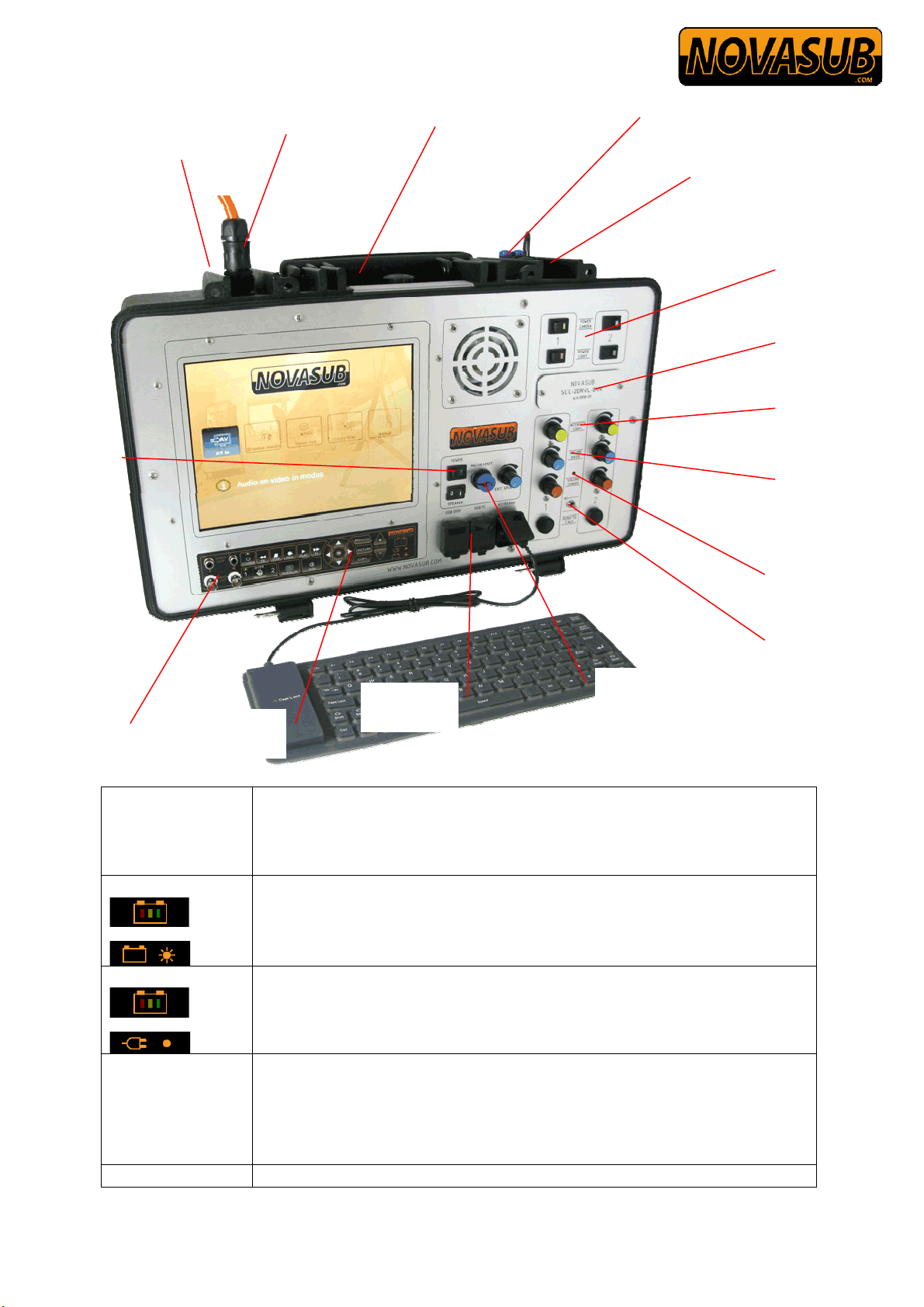
Power
Switches main power on
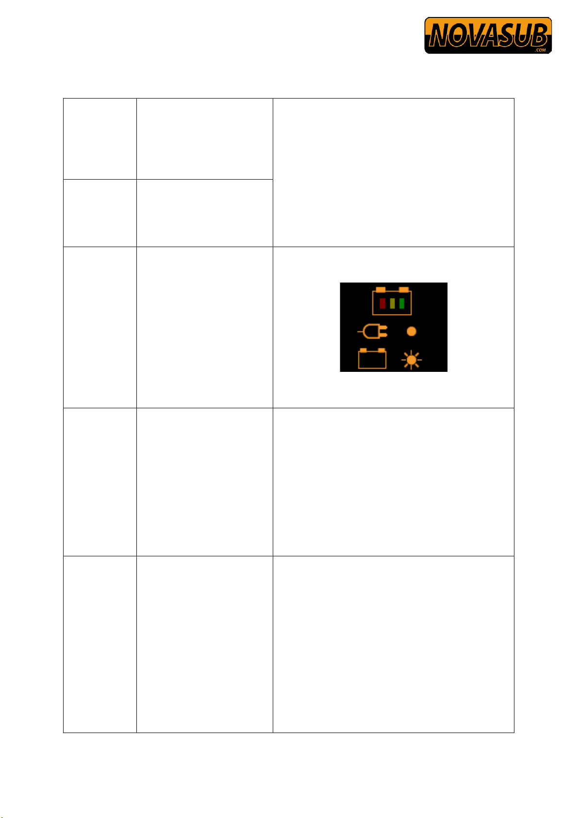
Batt. Level
Led indicating the level of the battery (Blinking) when there is
NO
external power (100-220 vac) connected
• 10-30 % • 30 - 80 % • 100 % Full
Charge level
Led indicating the level of the battery (Solid) when there is external
power (100-220 vac) connected and charging the internal battery (UPS)
• Bulk charging • Trickle charge • Maintenance charge
Speaker
Switches internal main speaker on or off
DVR audio to Switches DVR recorded audio to the internal speaker. The diver
Diver 1 cable
connector &
Bananaplug
sockets
Diver 2 cable
connector &
Bananaplug
sockets
Optional:
Bobox connector
Video &
Audio out
DVR USB
DVR
buttons
Ext. Mic and
headset
Keyboard conn.
Ext sopeaker
Camera &
Light switches
Light Intesity
Divers
Volume
control
Microphone
Diver cross-
Talk
Cable length
adjustments
Power
On/Off
Main power
Connector
Ext. Speaker
connector

Manual SCC-2DRVL-DVR Gen2
www.novasub.com
Rev 5
6
of
47
Manufactured by Seascape.nl
Speaker
communication to internal speaker will not be listened.
When LED is green, the DVR audio is set to radio.
Warning: Switch this option off during normal diver
communications.
DVR REC select
Selects if diver 1 or 2 video will be recorded on DVR.
Both divers audio and surface audio will be always recorded.
Power Camera
Switches camera on and off (LED indicates status)
Power Light
Switches light on and off (LED indicates status)
Intensity Light
Adjustment of LED light from 0 – 100 %
Volume Diver
Adjustment of Diver helmet speaker volume
Volume Tender
Adjustment of operators speaker volume
Cross Talk
Cross talk, operators control that diver 1 can talk to diver 2 while
toggling switch, and vice versa
PTT
Push to Talk buttons, press to speak to diver 1 or diver 2
Ext. Speaker
Adjustment of external speaker volume
Headset / Mic
Bulgin Multipin connection for standard headset with Mic and optional
Mic with PTT
USB disk USB connection for memory stick / pen drive or ext. harddrive
Keyboard USB keyboard connector for video overlay control and text input
USB PC USB connection to PC USB, the internal DVR Hard Disk will be
recognized as an external Hard disk on the PC
Diver Umbilical Multipin connector for Diver umbilical with video, light and comms.
Standard Novasub Multipin connector is the UTS 10 pin connector.

Manual SCC-2DRVL-DVR Gen2
www.novasub.com
Rev 5
7
of
47
Manufactured by Seascape.nl
Other connectors can be installed at order.
Separate yellow Banana sockets coonector for comms only
Audio Out
Diver 1 and 2 audio output
Video Output
Diver 1 and 2 video output, signal direct from camera. Video text
overlay is not available on this channel.
Video overlay
Switches the video overlay on and off
DVR
Switches the DVR on (green is on)
DVR controls
Stop,Rec,Return
See chapter 16,17
Video Adjust
Access
Manual SCC-2DRVL-DVR Gen2
www.novasub.com
Rev 5
8
of
47
Manufactured by Seascape.nl
3Quick startup
Plug in Main
power cables
Plug in external power
supply 100-220 vac. The
system will automatically
start charging the internal
battery. Even with the
main power switch off
Connect
diver
Umbilicals
Connect one or two diver
umbilical with Multipin
connector for video,light
and comms, or only
Banana sockets for comms
Switch Main
power on
If external 100-220 vac
power is supplied the
Charge Level will
indicate that the battery is
charging and the status of
the charge by color. (solid
LED)
When NO external power
is supplied the Batt. Level
is indicated by blinking
LED and indicates the
battery status by color
Switch main
speaker ON
Switch DVR
audio to
speaker OFF
Select Diver
I or II
Switch internal main
speaker on to hear the
divers
Switch DVR audio To
speaker OFF (Toggle left
down)
Select diver 1 or 2 to view
and record.
Switch on
the Camera
and lights
Toggle the camera and
light switches, status LED
indicates On or OFF
Rotate the Intensity Light
knob to the required
power

Manual SCC-2DRVL-DVR Gen2
www.novasub.com
Rev 5
9
of
47
Manufactured by Seascape.nl
Switch DVR
on
Press DVR button, the
LED will Lid indicating
on. After initialization
press OK to enter the
video In mode and the
selected diver camera can
be viewed
Volume
adjustments
Regulate the diver and
tender volume according
the requirements.
Note:
If Diver 1 or Diver 2 has
no umbilical connected
with helmet, turn down
both volumes of that
diver. Or else this line will
cause interference on the
radio and recordings.
Recording
Pause
Press Rec to start
recording
Press PLAY to pause
recording, press again to
resume
Playback
recorded
files
Press Browser or
Press RETURN Select
Brower Media using arrow
keys Press OK
Select HDD Select My
RecordingScroll to
filePress OK
Manual SCC-2DRVL-DVR Gen2
www.novasub.com
Rev 5
10
of
47
Manufactured by Seascape.nl
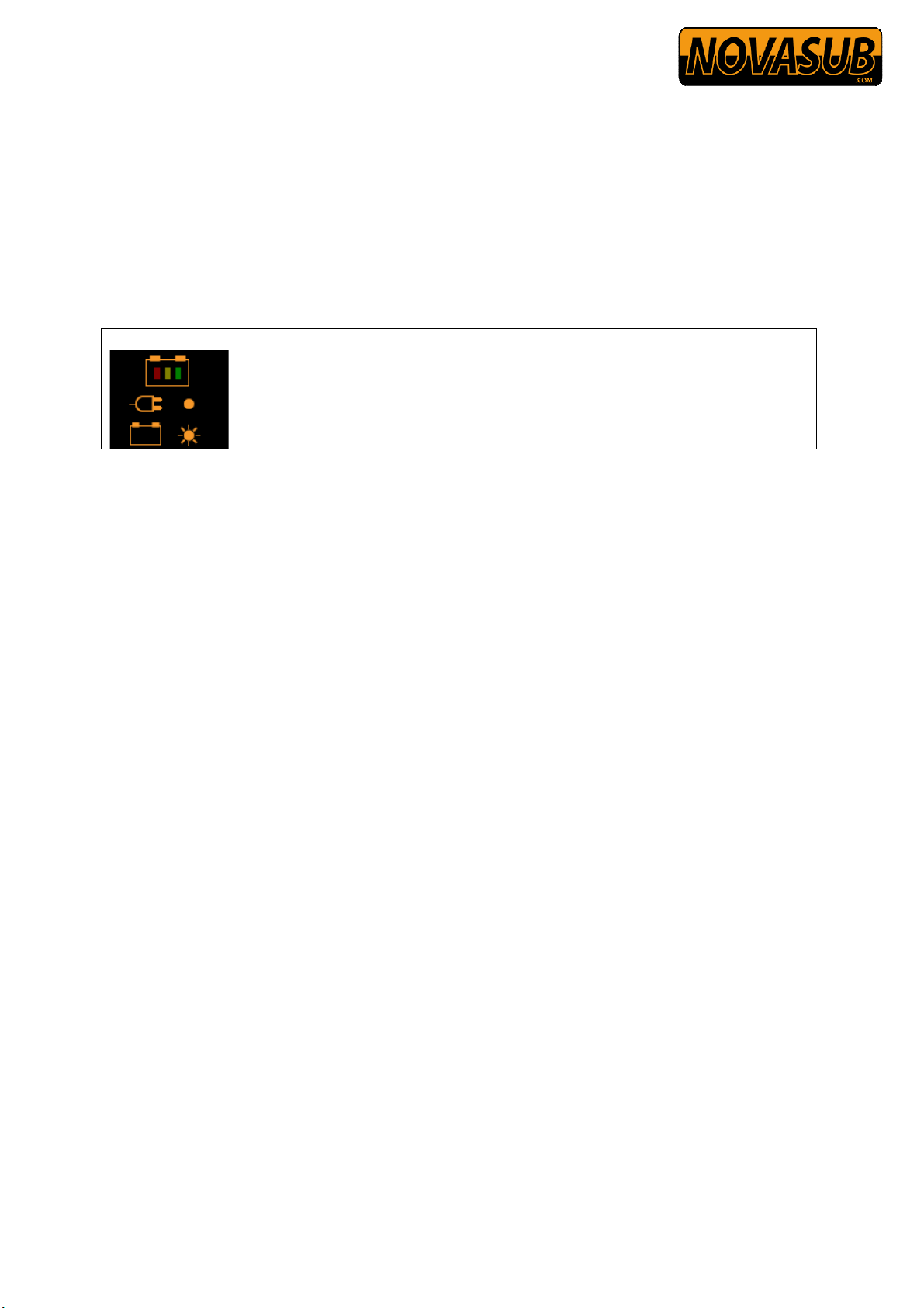
4Charging the system
When the external IEC plug is inserted on the top left of the case the internal battery will be
automatically charged. The system can be powered with 100 – 240 vac 50/60 Hz
The Charge level LED’s will indicate that the system is being charged and the status of
charge. Charging time for a fully discharged system will take approx. 10 -12 hrs.
When system is fully charged the batteries are automatically trickle charged to maintain full
capacity.
The Main power does not need to be switched on to the charge the system.
Charge level
Led indicating the level of the battery (Solid) when there is external
power (100-220 vac) connected and charging the internal battery
(UPS)
• Bulk charging • Trickle charge • Maintenance charge

Manual SCC-2DRVL-DVR Gen2
www.novasub.com
Rev 5
11
of
47
Manufactured by Seascape.nl
5Video configuration
The SCC has a built in video line driver for each camera. This video line driver allows the use
of video signal over twisted pair cable up to a maximum length of 400 m.
Also the line driver can be set for coax cable use.
The Novasub cameras are available with video line driver for video signal over twisted pair
and coax.
The Novasub CAMSSTP set for Twisted Pair can also be used on Coaxial umbilicals or
cables.
For correct video setting with video over TSP, the radio PCB has for each diver an
adjustment possibility to compensate the video signal for different cable length and
quality. Up to 400 m of length can be compensated over TSP.
5. Setting for Video transmission type
Remove the front panel serial number plate.
By switching several jumpers on the PCB the video transmission can be set for video over
coax cable or video over twisted pair cable. This is done for each channel (diver).
You can set one channel for coax cable transmission and the other for twisted pair
transmission.
5. . Set for video over Coax cable
Set on selected channel (Diver) set the jumpers 1x J101, 1x J201 to open, set jumper only on
the left most pin, leave the right pin open.
And set 2x JP102 & 2x JP202 to coax, both jumpers on the left 2 pins.
J101
JP102
J201
JP1
02

Manual SCC-2DRVL-DVR Gen2
www.novasub.com
Rev 5
12
of
47
Manufactured by Seascape.nl
5. .2 Set for video over twisted pair.
Set on selected channel (Diver) set the jumpers 1x J101, 1x J201 to closed, set jumpers on
both pins.
And set 2x JP102 & 2x JP202 to TP, both jumpers on the right 2 pins.
5.2 Video compensating settings for cable length over TSP
The following procedure explains the setting of the correct video signal for use of Novasub
video camera system over twisted screened pair cable.
To be able to access these switches and pot meters the front panel serial number plate needs to
be removed from the front panel.
Connect all umbilicals and video cameras.
Power up the system and select the diver camera you want to adjust.
Front view of radio PCB in SCC-2DRVL –(DVR) diver radio.
Left is Diver 1 en right is Diver 2
Video adjust
Diver 2
Video adjust
Diver 1
Manual SCC-2DRVL-DVR Gen2
www.novasub.com
Rev 5
13
of
47
Manufactured by Seascape.nl
Adjust for each diver accordingly.
Note: use a plastic screwdriver to be sure not to touch any components on
the PCB.
Set the adjustment to best video image, and move the camera over bright area’s to check
quality. Re-adjust if needed. Check also with overlay switched on, certain limits will
lose overlay.
Best adjustment is a bright image with nearly any brightness level change when
switching the text overlay on/off.
Cable length settings
all Off for Coax
1,2,3 or 4 ON for
different TSP cables
length
ADJ202
Brightness
Adjust to get the
correct brightness
ADJ201
Equalization
Adjust for the
correct video
transmission over
TSP.

Manual SCC-2DRVL-DVR Gen2
www.novasub.com
Rev 5
14
of
47
Manufactured by Seascape.nl
6Diver audio
The diver audio is standard set for a 2 wire communications (simplex).
The divers can only speak to each other when the surface operator pushes the cross-talk
switch to the desired direction.
The SCC-2DRVL-DVR can also be ordered (and set) for 4 wire communication (duplex)
The divers have an open 2 way communications with each other without any selection from
the surface. The surface will hear both divers and can talk to the desired diver by pressing the
corresponding PTT.
The audio comms is connected to the diver umbilical via the multipin connector (pins H,J) or
via the yellow Banana sockets
6. Diver audio adjust
The diver amplifier volume can be set on the PCB for different type of helmet microphone
speakers. The factory settings are based on a standard helmet microphone/speaker element.
If the volume is too low or too high, it can be adjusted with a potmeter for each channel.
The potmeters are hidden behind the front panel serial number plate. Remove the front panel
serial number plate.
Use potmeter ADJ303 for diver 1 and ADJ403 for diver 2.
Turn CCW for less amplification and CW for more amplification.
Diver audio
adjust

Manual SCC-2DRVL-DVR Gen2
www.novasub.com
Rev 5
15
of
47
Manufactured by Seascape.nl
7External Speaker
The SCC has a built in 10 watt amplifier to which a external 4-8 ohm (10-30w) speaker can
be connected. The external speaker has its own volume control.
All conversation, diver and tender are heard on the ext. speaker.
8Headset / Mic
The external headset/Mic connector can be used to connected the supplied headset with mic
and used with the SCC built in PTT to speak to the divers.
Another option is to us the headset/mic connector for an optional MIC with PTT to talk to the
divers. The internal speaker can be switched of if required.
Headset standard supplied with SCC, MIC-PTT is optional
Banana connection
or bare wire
External volume
control
Manual SCC-2DRVL-DVR Gen2
www.novasub.com
Rev 5
16
of
47
Manufactured by Seascape.nl
9BOBOX (optional)
The Bobox can be ordered at new order or post
ordered for integration on previously built systems.
The Bobox is an optional Break Out Box to use as an
remote extension for 2 diver communication. The
Bobox is standard supplied with 30 m cable. The
Bobox has a built in amplifier and speaker. Also PTT
for each diver and volume control of the speaker and
divers.
Also an external Headset/Mic can be connected.
All Tender-Diver and Diver communication are
heared on the Bobox as well as the SCC.
Also the SCC controls are fully functional.
Application:
•Remote setup out of the diver container at the
diver launching platform
•Remote setup in a control room for any
machinery
•Remote setup in a client area
The Bobox is connected to an optional connector installed on the SCC.
0 Duplex 4 wire communication (optional)
The SCC-2DRVL-DVR can also be ordered (and set) for 4 wire communication (duplex)
The divers have an open 2 way communications with each other without any selection from
the surface. The surface will hear both divers and can talk to the desired diver by pressing the
corresponding PTT.
The standard 10 pin connector needs to be replaced by a 12 pins connector to add the extra
two contacts for the 4 wire communication.
This procedure can be done on order or post order by shipping the SCC-2DRVL-DVR back to
Seascape or Novasub service centre.
Third party camera connection
The SCC-2DRVL-DVR is fully built to accept the standard Novasub video cameras.
However any brand of analog video camera can be connected to the SCC-2DRVL-DVR.
The standard voltage output to the camera connection is 31 vdc.
This can be configured to a lower voltage by Seascape at its factory.
On new orders please specify required voltage range.
Standard range are 12 vdc, 15 vdc and 24 vdc.

Manual SCC-2DRVL-DVR Gen2
www.novasub.com
Rev 5
17
of
47
Manufactured by Seascape.nl
2 Sensor data input on Video overlay (Optional)
The SCC-2DRVL-DVR can be supplied with a OSD-2 type video text&data overlay unit.
This overlay enables the input of different analog and digital sensors which can be displayed
on the monitor video overlay. The OSD-2 has the same standard function as the OSD-1 with
the extra sensor input and data display.
Standard extra data overlay
Standard the OSD-2 overlay unit is configured for the input of a de following sensors:
2. USD- Diver Depth sensor (D)
The USD-1 depth sensor is a analog pressure
sensor in a underwater housing with a 3 pin
connector. The sensor outputs a 4-20 ma signal
through the diver umbilical/cable to the SCC’s
overlay. The sensors are standard 0-60 MSW and
are so calibrated together with the SCC’s overlay
OSD-2 unit. Other pressure depth ranges are
possible.
2.2 Thickness Gauge (T)
The data of a Ultrasoon thickness gauge can be displayed
on the video overlay. Standard the OSD-2 is configured
for the Tritex Multigauge 3000.

Manual SCC-2DRVL-DVR Gen2
www.novasub.com
Rev 5
18
of
47
Manufactured by Seascape.nl
2.3 CP probe (CP)
The OSD-2 has a built in 0-2000 mV input which can be used with a underwater Proximity
Probe to measure the cathodic potentials.
2.4 Data output
The OSD-2 has standard a Rs232 output, which outputs all data in different ASCII strings.
This can be used by other data display instruments or software.
2.4. Data outputs
The values diver depth, thickness and cathodic potential are transmitted by RS232 - 9600 bps,
in the following ASCII strings:
$NSDD,160734,010911,05.05
Novasub diver depth, time (HHMMSS), date (DDMMYY), depth in meters and centimeters.
$NSTH,145134,010811,000.0
Novasub thickness, time (HHMMSS), date (DDMMYY), thickness in mm.
$NSCP,145133,010811,0339
Novasub cathodic potential, time (HHMMSS), date (DDMMYY), cathodic potential in milivolts.
All strings are ended with a carriage return and line feed.
2.5 Sensor connections
The depth, Thickness gauge and CP-probe are connected with the SCU through the divers
cable/umbilical to the 19 pins UTS multipin connector.
The CP probe negative potentional is connected to the Banana screw terminal connector
labeled CP- GND.
The rs232 port is a bulkhead Bulgin 8 pin connector labeled with RS-232.

Manual SCC-2DRVL-DVR Gen2
www.novasub.com
Rev 5
19
of
47
Manufactured by Seascape.nl
3 Connections
The SCC has several different type of connections for inputs and outputs.
3. Standard SCC with OSD-
Following connections are standard on the SCC with video overlay OSD-1

Manual SCC-2DRVL-DVR Gen2
www.novasub.com
Rev 5
20
of
47
Manufactured by Seascape.nl
Table of contents
Other Novasub DVR manuals


Popular DVR manuals by other brands

Dedicated Micros
Dedicated Micros BX2 User Supplement

avertX
avertX A800+ ProConnect quick start guide

Samsung
Samsung SRD-880D Quick manual

Sentry Surveillance
Sentry Surveillance RealEyes 17 Series Quick start manual

Honeywell
Honeywell HRDP16D1T0 quick start guide

REI
REI HD5 Care and maintenance quick guide


