NovaTec GSL Series User manual
USER GUIDE
MODELS:
>GSL-12
>GSL-19
Patent # 8,753,432 and 8,070,844
Vacuum Loaders
GSL Series
GSL-UG 17 June 2019
©2019 NOVATEC, Inc. All Rights Reserved
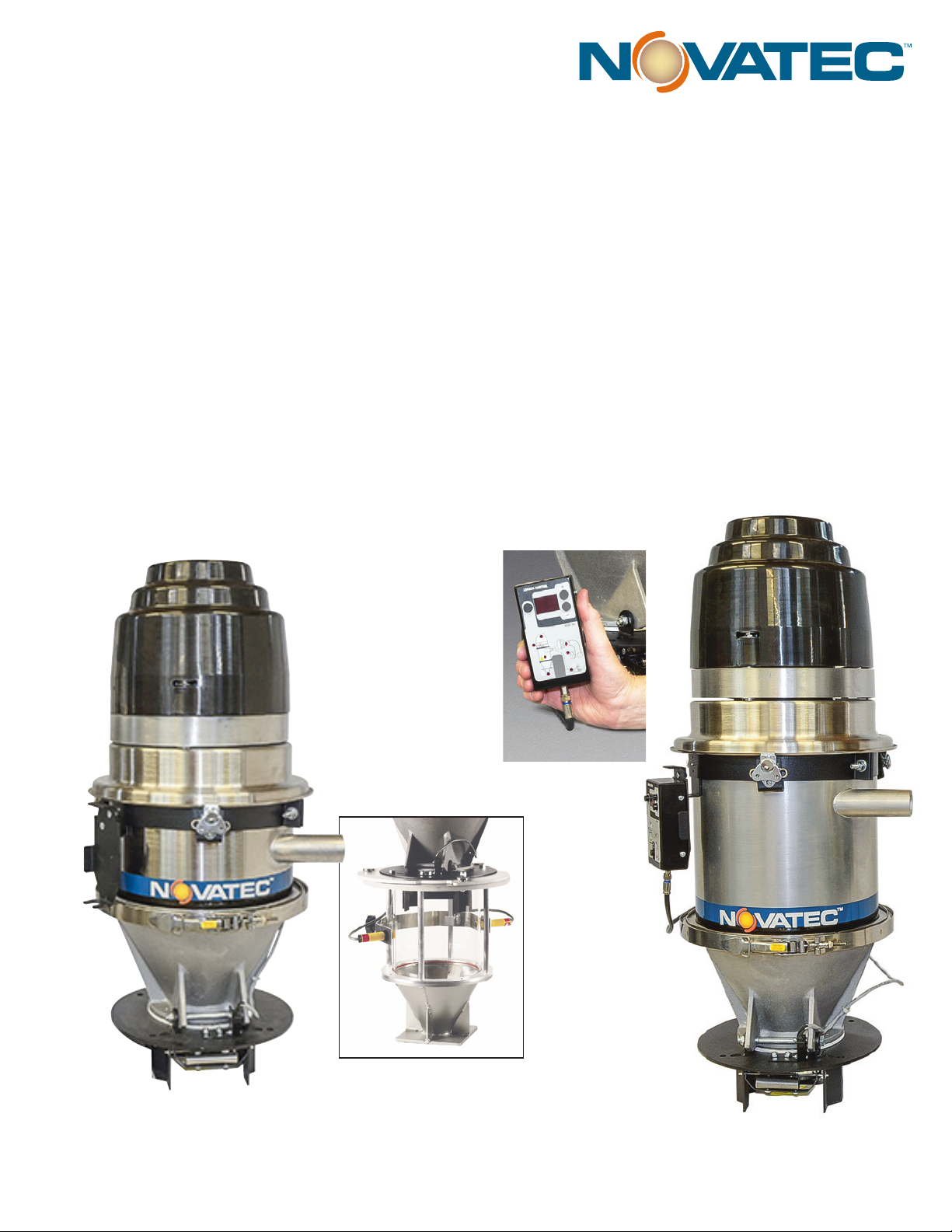
GSL-12
GSL-19
Oponal
machine mount
assembly
Remote
pendant control

In the space provided below you should record the model and serial
number(s) of your equipment and the date the equipment was received.
In the event you would need aermarket assistance our parts and ser-
vice department uses this informaon, along with the manual number, to
provide help for the specic equipment installed.
Please keep this instrucon manual, any relevant addendums, engineer-
ing prints and parts lists together for accurate documentaon of your
equipment.
NOTES
User Manual: GSL-UG 17 June 2019
Serial Number(s):
Model Numbers:
DISCLAIMER: NOVATEC, Inc., shall not be liable for errors in this instrucon
manual. Informaon can change without noce. Novatec makes no warranty of
any kind concerning the informaon contained herein, including, but not limited
to the implied warranes of merchantability and tness for a parcular purpose.
©2019 NOVATEC, Inc. All Rights Reserved.

Table of Contents
1 SPECIFICATIONS 4
2 UNPACKING AND INSPECTION 5
3 INSTALLATION 6
3.1 GSL 6
3.2 GSL MACHINE MOUNT MODELS 8
4 OPERATION OVERVIEW 9
6 ADJUSTING THE LOADER CONTROL 10
6.1 Loading Control System Terminology 12
6.2 Proporoning Valve Use 13
7 INITIAL STARTUP 14
8 ELECTRICAL CONNECTIONS FOR LOADER OPTIONS 15
9 TROUBLESHOOTING 18
10 Warranty Periods: 19

4
1.0 PRINCIPLE OF OPERATION
A Load Cycle begins with a compressed air blowback
pulse to clear any isolated material parcles or dust
buildup that may remain on the apper discharge valve.
This acon ensures a ght vacuum seal for each Load
Cycle.
The loader then acvates our powerful, maintenance
free, brushless motor to create a vacuum, which draws
material into a chamber. Aer the load me seng has
expired, the vacuum motor is turned o and the nega-
ve pressure in the chamber is relieved. Material in the
chamber then falls through the boom, past the apper
while compressed air is pulsed through the lter to dis-
lodge any contaminants or nes that may have accumu-
lated. This cycle is repeated as many mes as necessary,
unl the unit is shut o by the rise of the conveyed ma-
terial in the area below the loader which trips the level
switch, removing the ‘demand’ signal.
Machine mounted units do not have a apper valve or
demand switch, but instead ulize a clear sight tube,
which mounts directly to the machine throat, with a sen-
sor to control loader operaon based upon the level of
material within the sight tube. The sensor may be either
a capacitance style, with sensivity adjustment, or a pair
of photoelectric sensors, an emier and a receiver.
The boom ange of a Machine Mount unit is normally
supplied undrilled to allow the customer to drill the ap-
propriate mounng paern for a parcular process ma-
chine.
2.0 UNPACKING AND INSPECTION
NOVATEC Vacuum loaders are shipped complete, with
all controls for automac operaon. The only ulies
required are a 115 volt power supply and clean, dry com-
pressed air at approximately 80 PSI.
Aer receipt of the unit, completely inspect it for dam-
age. All units are packaged securely at the factory. Please
report any damage to your carrier promptly.
3.0 SPECIFICATIONS
NOVATEC GSL Series vacuum loaders are completely
automac self-cleaning vacuum loaders designed to con-
vey virgin pellets and regrind materials from storage con-
tainers to drying hoppers or directly to process machines.
Each unit is shipped complete with all controls for imme-
diate operaon, and include a hardware package. The
hardware package includes 15 feet of exible vacuum
hose, hose clamps and a material pick up lance, plus a 12’
extension cable for remote mounng the standard Con-
trol Pendant.
The GSL is designed for mounng on drying hoppers.
The GSL can be modied for use as a machine mount
unit on processing machines by adding a machine mount
assembly with an 8, 12, or 16 lb. capacity site glass with a
height adjustable photo-eye demand switch.
OPTIONS:
2” Inlet: (in lieu of 1.5”)
Extended Wear Package: Recommended when loading
abrasive materials - contact factory
Alternate Glass Size: 12 lb glass (adds 4” to height) or
16 lb glass (adds 7” to height)
Kit includes glass, twist-lock plug and photo-eye
Alternate Mounng Flange (7” x 7” with 3.5” opening)
removes 1.5” from height
ACCESSORIES:
(one included with each GSL)
(Includes coupler, wand,
hose and clamps.) 1.5”and 2.0” O.D.
30mm dia., 2m cable
Sensor (for
machine mount models)
5
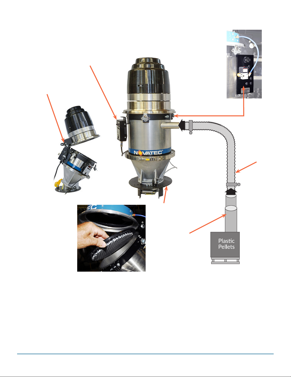
1. Install exible hose, secured with hose clamps at both
ends, from feed tube to material inlet tube of loader. A
Proporoning Valve, if included (see separate instruc-
ons) is installed on the material inlet tube with a com-
pression style coupling.
2. Plug power cord into 115 VAC power source. Note
amperage lisng on loader for correct voltage and capac-
ity.
3. Install exible compressed air line to the solenoid
valve ng (below lid hinge). Source should provide
clean, dry compressed air supply 80 -100 psi. Use only
full-ow quick disconnect ng for best blowback per-
formance. CAUTION: Use a second wrench to hold the
ng on the GSL securely while ghtening the hose t-
ng. DO NOT apply direct pressure, or damage the GSL
ng or an air leak could result. A compressed air lter
(sold separately) is recommended for protecon of pneu-
mac components.
Locate HINGE away from
operator for easy cleaning
GSL Mounng Plate
(see page 6)
Feed Tube Inserted
into material
Domed lter
stays in place
when lted.
115 VAC
Power Cord
Connect Fing on
Solenoid Valve to
Compressed Air
(Pilot for Blowback)
(Not visible)
Material Line
Connecon
Control Pendant
(see page 6)
4.0 INSTALLATION
4.1 GSL
1.
2.
3.

6
• New or exisng NOVATEC hoppers will allow
mounng the GSL directly. Hoppers with large
openings for 5” dump throat models will use the
VL-12 to VL-38 adaptor, included with the GSL unit.
You may bolt the loader base plate on the receiving
hopper securely, and then install the GSL cast cone
with the front hinge pin and rear ange locking tab.
CAUTION: FASTEN GSL FLANGE TO RIGID
MOUNTING SURFACE BEFORE OPERATING OR
TILTING THE HOPPER BODY. USE ONLY LOCK-
ING, CAPTIVE FASTENERS.
• For mounng to non-NOVATEC hoppers, note
your model of GSL and prepare the hopper to be
loaded with the appropriate cut-out and bolt pat-
tern according to the diagrams above. These have
been designed to allow for direct mount into several
non-NOVATEC mounng paerns.
• Secure fasteners should be employed, fastened per-
manently to the hopper lid to prevent possible drop-
ping into the hopper/material.
10.38” O.D.
9.00” Dia. Bolt Hole Circle
.3125” Dia. Typ. (4 places)
Alternate Mounng Flange (7” x 7” with
3.5” opening) removes 1.5” from height
7
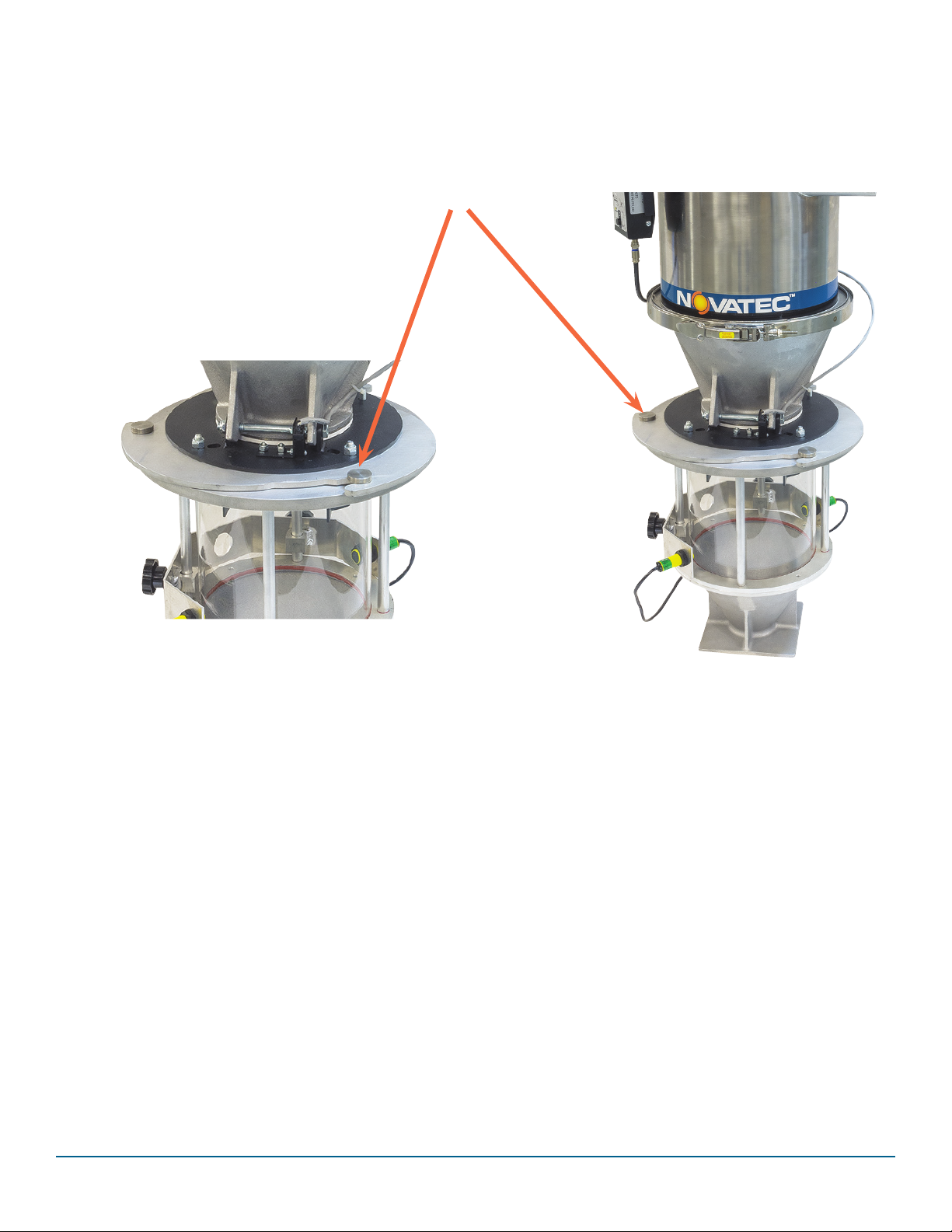
4.2 GSL MACHINE MOUNT MODELS
The upper part of the machine mount model sll lts for
ease of access to clean/replace lters.
Upper and lower parts of machine mount
model are connected together with a plate
that slides into place.
A detent pin locks the plate in place. GSL-19 with adjustable with oponal ma-
chine mount assembly and Photo Eye Level
Sensor installed.
8
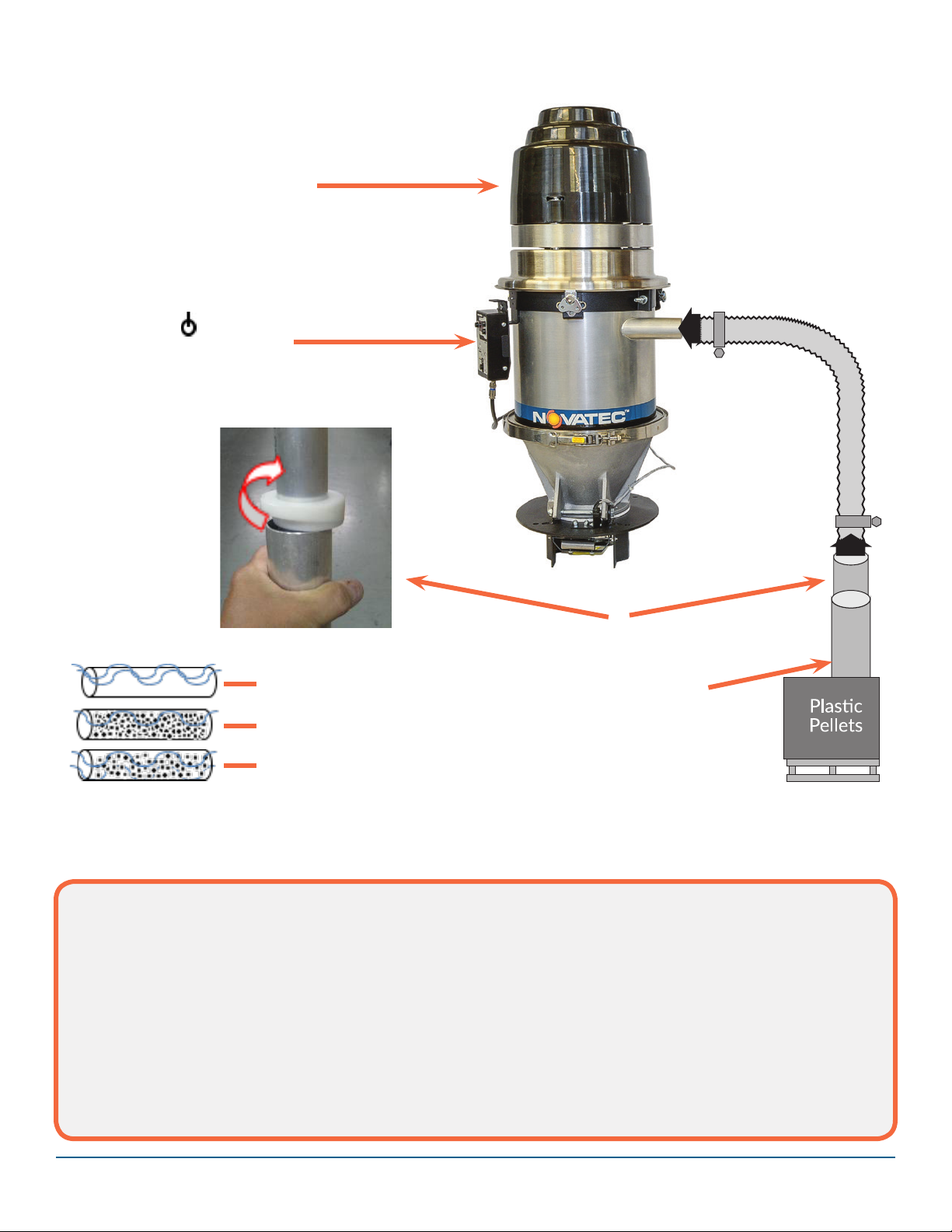
1. The feed tube joins air with material and it should
be plunged (and kept) in the material supply, but allow
upper secon of feed tube to remain above material
level.
2. Adjust load me. See next page for detailed in-
strucons on control sengs and opons.
3. To allow opmum loading and longest lter life,
adjust load me to ll the loader without over lling.
To idenfy opmal load me, operate the motor unl
material stops moving and note the corresponding ll
me. This means the loader is OVER FILLED. Sub-
tract 5 seconds from the over-lled me to limit pre-
mature lter blinding.
4. Rotate the feed tube ring for the best air to material
mixture. The best mixture of air and material will allow
material to ow eciently, with the right proporon of
conveying air, without clogging and without rapid hose
wear. Be sure material ows into loader consistently
from start to nish, without surging or oang at the
pickup or loader inlet.
3. Vacuum motor should ll loader
unl 5 seconds before pellets stop
moving through the convey hose
and no more.
Rotate to change air
inlet opening
2. Press buon to turn on
loader and adjust load me
with + buons.
Air inlet
4. Adjust conveying air with
feed tube ring
1. Assure that the feed tube
is inserted into material
Too much air…slow loading
and hose wear more likely
Too lile air…plugged
material line is possible
Good mixture of air and
material

9
Solenoid Valve
(Air) Connecon
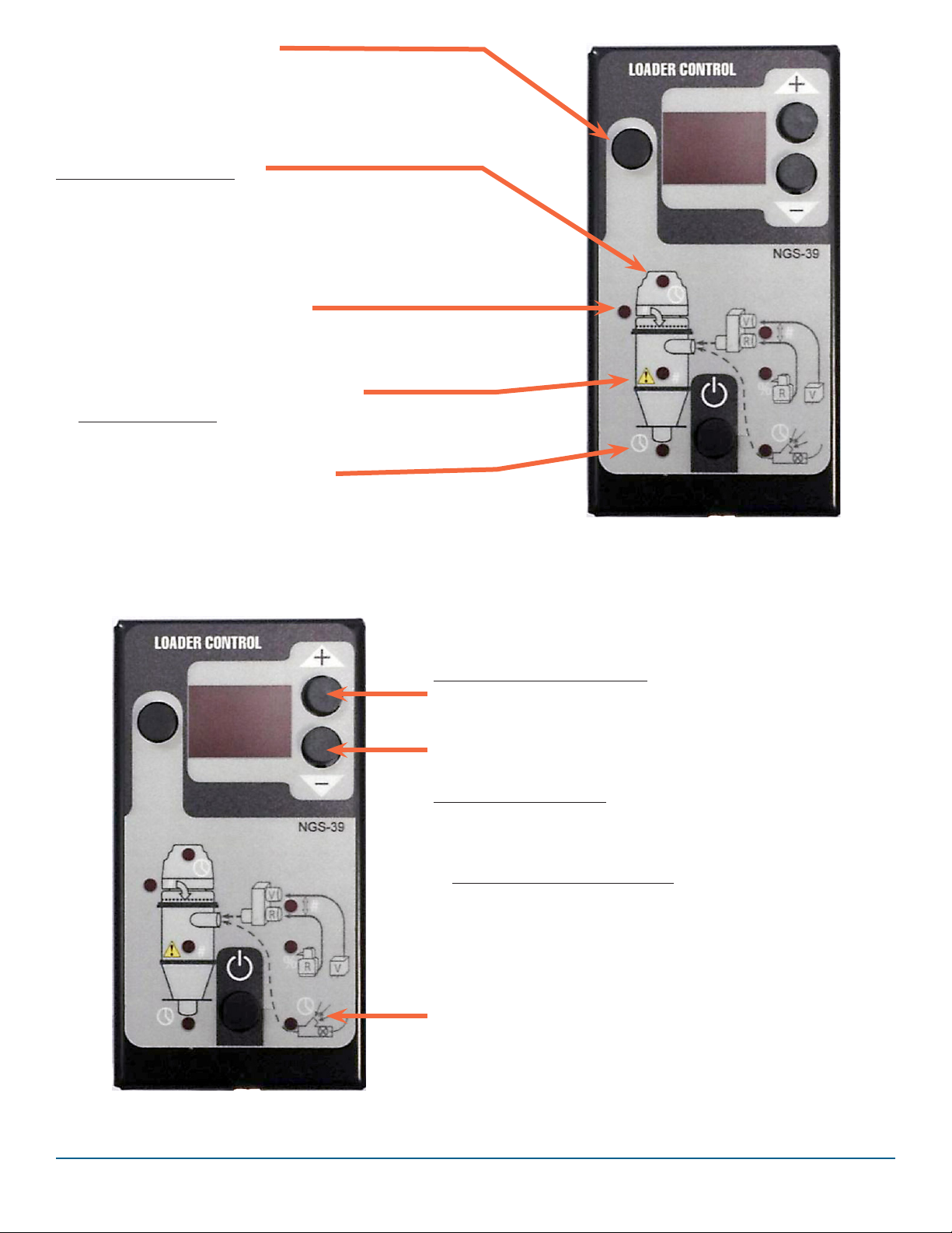
6.0 ADJUSTING THE LOADER CONTROL
or disables loading.
Power is only disconnected
by unplugging the power cord.
POWER*
Press for On or O
Display shows “ON”
Force Alarm Reset
Motor Plug
Connecon
Demand Switch
Connecon
Power
Connecon
Pendant Cable Connector
Control Box
10
SELECT FUNCTION BUTTON
● Buon selects funcons for
viewing and/or changing.
● Selected funcon lights up, below.
● Silences Alarm (does not reset alarm)
STANDARD FUNCTIONS
Seconds per load
Default = 15s (suggested Max = 20s)
Do not exceed 30s / Do not overll
Damage may result
“XY”
X=loads between clean cycles
Y=air charge (Y*0.4s)
See Blowback Funcon descripon (p. 12)
‘No Load’ cycles to create alarm
“0” = Alarm disabled.
See Alarm Funcon descripon (p.12)
Seconds or minutes (M)
(Forced pause between Load Cycles)
VIEW and CHANGE SETTINGS
● Selected seng appears in window
● Increase (+) or decrease (-) values
● Display defaults to show “ON”
● Display shows “AL” for alarm condion
OPTIONAL FUNCTIONS
PROPORTIONING: Requires oponal Valve.
● LAYERS: # of alternang VIR/REG cycles per load.
‘A’ = Automac control calculated Layers.
TOTAL CONVEY TIME per Load
Regrind = (Motor On – Purge) * REG %
Virgin = (Motor On – Purge – Regrind)
NOTE: Divide these mes by LAYERS value for
individual layer cycles mes.
REGRIND: % of Convey Time for regrind
Uses specied me to empty the
material line. Inserted as nal interval of
total MOTOR ON me (does not extend
MOTOR ON me). Requires oponal Valve.

11
Loading and Purging
Although this term may not appear on all controls, it is
helpful to use for understanding the vacuum-on me of an
individual receiver. The total vacuum-on me of a loader
(the length of me the vacuum motor is “ON”) can be
referred to as FILL me. All funcons that happen while
the vacuum motor is “ON” (regrind proporoning, pocket
conveying, purging, etc.) is all part of the FILL me.
The vacuum me that a loader uses to introduce material
into a material conveying line is LOAD me. The term
may be thought of as ‘loading the material line’. This term
is important to understand when purging conveying lines,
to disnguish between the me the purge valve is opened
(LOAD me) compared to the me it is closed (PURGE
me). On loaders that have no purge valves, LOAD me
equals FILL me. On systems with purge valves, LOAD
me is just the rst part of the FILL me. Purge me is
the conclusion of FILL me.
The vacuum me that a pocket or purge valve is closed to
material ow, but vacuum air connues to ow thru the
conveying line to clean out the material conveying line is
referred to as PURGE me.
Because the funcons are idencal, the term PURGE me
is used for purging systems and pocket conveying systems
for cleaning out the conveying line aer loading.
Fill Time
(Vacuum Motor “ON”)
Vacuum
Motor “ON”
LOAD
Time
(purge
valve
open)
Times are set in seconds.
Purge or
Pocket
Valve
CLOSES to
Material
flow
PURGE
Time
(purge
valve
closed)
Vacuum
Motor “OFF”
Material Outlet, connected
to receiver Inlet
Solenoid: Connecon to con-
trol and connecon to com-
pressed air supply. Material #1 inlet,
typically Virgin
Material #2 inlet,
typically Regrind

12
7.0 INITIAL STARTUP
Press the Power Buon on the Control Pendant unl
‘ON’ appears on the display to enable loading.
IF a material demand exists, the loader will begin
loading.
NO LOAD ALARM FUNCTION
The NO LOAD ALARM is enabled through the control
pendant by entering a display value >0
when the No Load Alarm LED is illumi-
nated (see photo).
NO LOAD ALARM occurs when the
counter reaches the user selected Alarm
Set Point value.
• The Loader connues load aempts
aer the ‘Alarm’ Output is energized.
• If 10 cycles pass without the alarm
counter being cleared, the Loader will
shut down and ash “OF” on the pen-
dant control.
CLEARNING AN ALARM CONDITION:
• Pressing the ‘Select Buon’ will silence the ‘alarm’ out-
put. The alarm counter will connue.
• The alarm clears when the hopper is full.
• Aer Alarm Shutdown, press the power buon to clear
the alarm and restart operaon.
BLOWBACK FUNCTION
Blowback, when enabled for lter cleaning, pulses before
and aer any load cycle designated for blowback by the
control sengs.
Blowback also pulses briey at the beginning of each
load cycle, just as the motor begins operang. This blow-
back pulse is intended to clear any material residue from
the discharge apper and ensure a clean vacuum seal for
opmal loading.

13
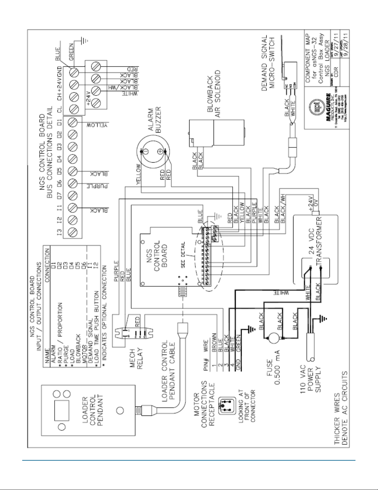
8.0 ELECTRICAL CONNECTIONS FOR
LOADER OPTIONS
1. Remove the loader control enclosure, and care-
fully p the enclosure out without straining wires
connected to the control.
2. Locate the correct terminals for the device you
are connecng, as shown in the diagrams that fol-
low, and connect the wires carefully. Use care as
some terminals accommodate mulple wires.
3. Route the cable out of the control box, through
one of the slots in the side. Tightly install a e
wrap (not included) onto the cable, inside the
control enclosure to prevent the cable from being
pulled out of the box.
4. Tip control box back into place and ghten top
screw.
14

15

16
9.0 TROUBLESHOOTING
Most loader problems are a result of a dirty lter, air leaks or improper adjustments.
These items should be checked before assuming equipment failure.
Motor will not run A, B, C, H, and L
Inadequate or no vacuum D, E, F, G, J
Inadequate or no material ow D, E, F, and G, I, K
Motor runs but proporoning solenoid not operang L
CHECK CONDITIONS SOLUTION
A. Power Supply No voltage or voltage incorrect Check incoming
v o l t a g e a t o u t l e t p o w e r s u p p l y
B. Stop/Start Switch No voltage through switch Replace switch
C. Vacuum motor No voltage at motor See A,B, & L
D. Filter Filter dirty Replace lter
(Also see G & J)
E. Air Ducts Obstructed Remove obstrucon
F. Leaks in system Air leaking into system Replace gaskets &
repair leaks as necessary
G. Blowback air Low pressure Increase pressure
pressure incorrect (not to exceed 125 psi)
H. Limit switch No voltage through switch Replace switch
I. Load Time Chamber not lling suciently Increase load me
Chamber over-lling Decrease load me
J. Pulse rate Insucient to clean lter Increase rate
K. Dump me Insucient to allow complete Increase me
emptying of chamber
L. Pulse solenoid Correct voltage at solenoid Replace solenoid

17

18
10.0 WARRANTY
NOVATEC, INC. oers COMPREHENSIVE PRODUCT WARRANTIES on
all of our plascs auxiliary equipment. We warrant each NOVATEC man-
ufactured product to be free from defects in materials and workman-
ship, under normal use and service for the periods listed under “Warran-
ty Periods”. The obligaon of Novatec, under this warranty, is limited to
repairing or furnishing, without charge, a similar part to replace any part
which fails under normal use due to a material or workmanship defect,
within its respecve warranty period. It is the purchaser’s responsibility
to provide Novatec with immediate wrien noce of any such suspect-
ed defect. Warranted replacement parts are billed and shipped freight
pre-paid. The purchaser must return the suspect defecve part, freight
prepaid and with idenfying documentaon to receive full credit for
the part returned. Novatec shall not be held liable for damages or delay
caused by defects. No allowance will be made for repairs or alteraons
without the wrien consent or approval of Novatec.
The provisions in equipment specicaons are descripve, unless
expressly stated as warranes. The liability of Novatec to the purchaser,
except as to tle, arising out of the supplying of the said equipment, or
its use, whether based upon warranty, contract or negligence, shall not
in any case exceed the cost of correcng defects in the equipment as
herein provided. All such liability shall terminate upon the expiraon
of said warranty periods. Novatec shall not in any event be held liable
for any special, indirect or consequenal damages. Commodies not
manufactured by Novatec are warranted and guaranteed to Novatec
by the original manufacturer and then only to the extent that Novatec
is able to enforce such warranty or guaranty. Novatec, Inc. has not au-
thorized anyone to make any warranty or representaon other than the
warranty contained here. Non-payment of invoice beyond 90 days will
invalidate the warranty. A renewed warranty can be purchased directly
from Novatec.
Please note that we always strive to sasfy our customers in whatever
manner is deemed most expedient to overcome any issues in connec-
on with our equipment.
Note: All warranty periods commence with the shipment of the equip-
ment to the customer.
(Except 1-Year on Non-Novatec Buy-Out Items)
NovaWheel™ Dryers *
Dual Bed Dryers
NovaDrier *
NDM-5 Membrane Dryer
Gas-Fired Process Heaters
Gas-Fired Regeneraon Heaters
Drying Hoppers
Central Drying Hopper Assemblies
Heater/Blower Units and Hot-Air Dryer
Silo Dehumidiers
NovaVac Dryers *
Nitrodry Nitrogen Dryers
DryTemp Plus
FlexTouch™ Series Controls
FlexXpand™ Series Controls
OpFlex™ Series Controls
PLC Communicaons Modules
Greenboard Communicaons Modules
LOGO! Mini PLC
MCS-600 Series Controls – (Distributed I/O)
MCS-400 Series Controls
CL Silo Manager
MoistureMaster®
Resin Blending and Feeding to Include:
WSB Blenders, MaxiBatch & Feeders *
Gaylord Sweeper Systems
C and NC Bessemer Series Cuers
NPS Bessemer Series Pullers
NPC Mini Puller/Cuer
All NS Series Servo Saws
Rx SmartMed Extrusion Products
All Cooling and Vacuum Tanks Manufactured by Novatec
GSL Series Vacuum Loaders
GlassVu Loaders, Receivers and Hoppers
VL/VLP Series Loaders
VRH, VR, VR-FL, VRP & VRM Series Receivers
Compressed Air Loaders
AL-B Barrel Loader
Cyclone Dust Collectors
Conveying System Accessories
Surge Bins
Valves and Accessories
Electronic Metal Separators
Quick Select Manifolds
Tilt Tables
Filter Dust Collectors
Drawer Magnets
Velocity Control Valves
** VPDB Vacuum Posive Displacement Pumps
** SVP Vacuum Pumps
** MVP Vacuum Pumps
** Railcar Unloading Systems
** - When a MachineSense® data plan is acvated for products with **, Novatec automacally extends the warranty to 5 years.
The data plan must be acvated within 60 days aer product shipment, and remain acve through the warranty period to maintain extended warranty
eligibility. The rst 6-months of data plan usage is free from Novatec.
Infrared Dryers
UltraVac Vacuum Pumps
Vacuum Regenerave Blower Pumps
Custom Equipment of any kind unless otherwise specied

19
Exclusions:
Roune maintenance/replacement parts are excluded from the war-
ranty. These include, but are not limited to: hoses, desiccant, lters,
lter elements, wiper seals, gaskets, dew point sensors, infrared lamps,
motors, internal solenoids, fuses and motor brushes. Use with abrasive
materials will void the warranty of any standard product. Wear resistant
opons may be available to extend usable service life with abrasive ma-
terials. Novatec reserves the right to limit the warranty if the customer
installs replacement parts that do not meet the specicaons of the
original parts supplied by Novatec.
1. NovaDrier™ and NITROdry™ warranty is void if coalescing lters are
not replaced on a 6-month or yearly basis (per instrucon manual)
and/or membrane has been exposed to ozone.
2. NovaVac Dryer -The ability of the canisters to hold vacuum will be
compromised if the vacuum seal edge is damaged from mishandling.
We do not warranty canisters damaged from improper handling. We
do, however, warranty the seals.
3. LOAD CELLS on our WSB’s are covered by Novatec standard warran-
ty as long as they have not been damaged from improper handling.
4. Desiccant Wheel Warranty will be void if the wheel has been exposed
to plascizer, dust or other contaminants as a result of negligence on
the part of the processor.
5. DryTemp+ - We assume no responsibility from equipment failures
resulng from untreated or improperly treated water.
1. Repaired or altered without wrien approval of NOVATEC unless
such repair or alteraon was, in our judgment, not responsible for the
failure
2. Which has been subject to misuse, negligence, accident or incorrect
wiring by others
3. Warranty is void if processing rates exceed manufacturer-recom-
mended levels or if damage is caused by ineecve power isolaon
and/or power spikes/sags or incorrect installaon.
NOTE: All condions and content of this warranty are subject to chang-
es without noce.

Drying > Conveying > Blending > Downstream
222 East Thomas Avenue
Balmore, Maryland 21225
www.novatec.com
Phone
410-789-4811 or 800-938-6682
24 Hour service: 800-938-6682
Fax: 410-789-4638
Email
Parts: parts@novatec.com
Service: service@novatec.com
Sales: sales@novatec.com
This manual suits for next models
2
Table of contents


