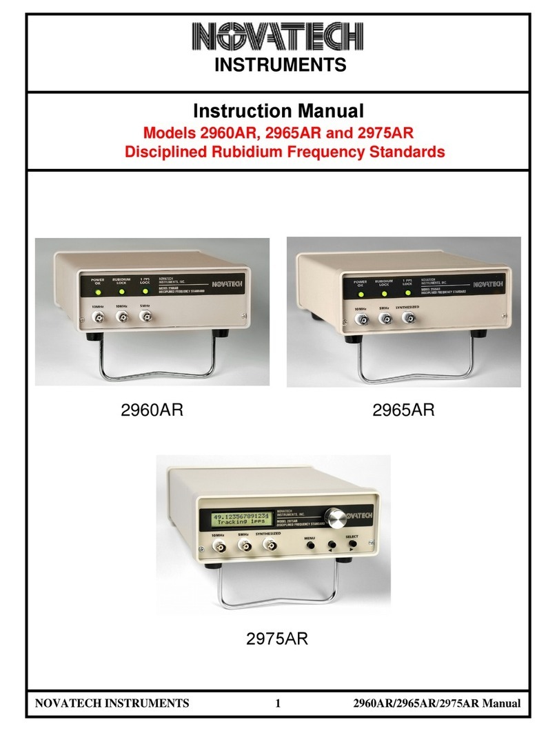
Novatech Instruments 1450B User manual

NOVATECH INSTRUMENTS 11450B Manual
INSTRUMENTS
INSTRUCTION MANUAL
Model 1450B
Disciplined Rubidium Frequency Standard
Model 409B
Table of Contents
Section Page Contents
12Description
22Specifications
33Installation
43Operation
531 PPS
64Performance Test and Calibration
6Warranty

NOVATECH INSTRUMENTS 21450B Manual
1.0 DESCRIPTION
1.1 The Model 1450B is a rubidium frequency standard
which can be disciplined to an external 1pps (one pulse
per second) reference signal. This 1pps is commonly de-
rived from primary, or other standards, such as GPS
(global positioning satellite).When disciplined to 1pps,
the 1450B provides primary standard accuracy and sta-
bility.
1.2 The 1450B provides one fixed frequency sinewave
output of 10MHz and up to 8 additional auxiliary outputs
that can be fixed sine or TTL or synthesized sine or TTL.
The 1450B is particularly useful in applications which
require non-standard or customer specified frequencies.
The auxiliary outputs are locked to the internal rubidium
oscillator
1.3 The most recent version of this manual can be found
on the Novatech Instruments web site.
2.0 SPECIFICATIONS
2.1 FREQUENCY STABILITY ( f/f, Typical)
Short Term: t=1s <3x10-11
t=10s <1x10-11
t=100s <3x10-12
Aging: Monthly <±5x10-11 after 1 month
Yearly <±5x10⁻¹⁰ after 3 months
Holdover (24Hours, ±2oC): <±1x10-11 (<±1s after >10x
1pps tracking time constant.)
Temperature: +5 to +45oC <±1x10⁻¹⁰
Line Voltage: ±10% <±5x10-12
2.2 FREQUENCY ACCURACY
At shipment: <=±5x10-11 at 20oC.
Retrace: <=±5x10-11 from last frequency after 1hour ON
and 24hours OFF (constant environment).
2.3 FIXED SINEWAVE OUTPUTS
10MHz, 1VRMS ±0.25VRMS into 50
2.4 SYNTHESIZED SINEWAVE OUTPUT
Frequency programmable from 100Hz to 50MHz in
0.1Hz steps.
Amplitude: 1VRMS±0.25VRMS at 10MHz into 50
(±3dB from 100Hz to 50MHz, referenced to 10MHz).
Phase Noise: Typical, <140dBc, 10kHz offset, 1MHz
output.
Harmonics: Typical <-45dBc, spurious: <-55dBc.
2.5 SPECTRAL PURITY (10MHz fixed output,
typical)
Harmonic <-25dBc.
Spurious/Non-Harmonic/Sub-Harmonic: <-45dBc.
2.6 PHASE NOISE (Typical, 10MHz output, 50)
Frequency Offset dBc
1Hz -70
10Hz -90
100Hz -120
1kHz -140
10kHz -140
2.7 1pps IN and OUT
1pps IN: DC-coupled, accepts TTL or CMOS. 1pps
OUT: TTL, 133s negative pulse width. Typical output
jitter: 20ns peak-peak (1 minute measurement time).
2.8 ENVIRONMENTAL
Temperature: +0oC to +50oC operating.
Humidity: 80% to 31oC, decreasing linearly to
50% at 40oC.
2.9 SIZE
3.47” H, 16.73” W, 12.0” D, standard 19” rack.
2.10 CONNECTORS
BNCs on rear panel for fixed 10MHz sine output 1pps
input, 1pps output and eight auxiliary outputs.
2.11 LINE POWER
120/240VAC ±10%, 50/60Hz. 30VA (50VA max during
warm up <20minutes). (internal line voltage switch)

NOVATECH INSTRUMENTS 31450B Manual
2.12 FRONT PANEL INDICATORS
POWER OK: AC power is applied and on.
RUBIDIUM LOCK: Green: Oscillator is locked.
Red: Warm-up.
1 PPS LOCK: Locked to and tracking a 1pps input.
2.13 ACCESSORY
GPS1: Matching GPS smart antenna system.
3.0 INSTALLATION
WARNING:
The 1450B line power input receptacle is provided with a
3-wire cord. Do not defeat the grounded conductor.
3.1 Power Connection. Verify that the rear panel indi-
cates your line power (120VAC or 240VAC
50Hz/60Hz). Connect the provided 3-wire line cord to
your power source. The power switch is built-in to the
input module on the rear panel. Line voltage is selected
by an internal switch and set at the factory.
3.2 1450B Installation. The 1450B requires no user set-
up beyond the application of line power and connection
to your application. Connect your 50 coaxial cables to
the appropriate front panel BNC. See below for 1pps
connections and use.
NOTE:
If you plan to use your 1450B as part of a
calibration system or house standard, it is suggested
that it be powered from an uninterruptable power
supply (UPS) (along with your 1pps source, if used).
4.0 OPERATION
4.1 Power on. After power is applied, the 1450B POW-
ER OK LED will illuminate green. This indicates that
the applied line power is within tolerance and the unit is
functioning.
4.2 Rubidium Warm-up. After power is applied, the
1450B will take up to 20 minutes to reach Rubidium
Lock. During Rubidium warm-up time, the front panel
LED labelled RUBIDIUM LOCK will illuminate red.
When the lock has been achieved (f/f<±1x10-8), this
LED will illuminate green. This function is independent
of 1pps tracking.
NOTE:
During the Rubidium locking process, the front panel
RUBIDIUM LOCK LED may switch between red and
green. A steady green indicates LOCK.
4.3 Proper operation in stand-alone mode, without
a 1pps connection, is indicated by a green POWER
OK LED and a green RUBIDIUM LOCK LED.
The 1pps LED will remain off.
NOTE:
The 1450B will meet the specified accuracy within a few-
hours after power-up. For applications requiring verifi-
cation of long-term stability, the periods shown in the
specifications will have to be met.
4.4 See the section “1pps Operation,” below, for details
on 1pps connections and operation.
5.0 1pps OPERATION
5.1 1pps In and Out. The 1450B is equipped with
rear panel BNC receptacles which accept a 1pps
input and provide a 1pps output. Use of 1pps allows syn-
chronization of multiple 1450B, as well as providing a
means of auto-calibration.
5.2 The 1450B will accept a long-term stable 1pps sig-
nal, typically derived from a GPS (global positioning
system) receiver or from another frequency standard. It
will auto-adapt to the supplied 1pps and adjust the inter-
nal Rubidium Oscillator to match the long term average
frequency derived from the 1pps. The auto-adaptive al-
gorithm selects the best tuning time constant based upon
the stability of your supplied 1pps.

NOVATECH INSTRUMENTS 41450B Manual
5.3 For low-jitter 1pps inputs (<20ns), the approximate
tuning time constant will be 1,000 seconds. A typical
timing receiver system, such as the GPS1 (with approxi-
mately 100ns peak-peak 1pps jitter), requires a time con-
stant of approximately 10,000 seconds (about 3 hours)
for optimum tracking.
5.4 For noisier 1pps inputs, the time constant may in-
crease to 100,000 seconds. If the input is too noisy, the 1
PPS LOCK light will not illuminate.
5.5 Proper operation when tracking a 1pps signal is indi-
cated by all three front panel LEDs illuminated green.
NOTE:
Due to these long time constants necessary to track a
1pps input, temperature variations can cause fluctua-
tions in the relative phase of the 10MHz output and the
1pps output.
NOTE:
The f/f tracking range of the internal Rubidium
oscillator is approximately ±1x10⁻⁸. If your 1pps sources
in error, but within these limits, the 1450B will adjust to
your source. This allows multiple units to be synchro-
nized even in the absence of an absolute reference.
NOTE:
The auto-adaptive frequency adjustment has a resolution
of ±5.12x10⁻¹³.
CAUTION:
Do not connect the 1pps input and 1pps output on an
instrument together. This will force the instrument to
track a moving value and reach its adjustment limit.
5.6 The 1450B is configured for automatic self-
calibration. When continuously connected to a stable
1pps source, it will auto-save the disciplined frequency
value into non-volatile calibration memory every 24
hours. The last-saved value will be used at next power on
or when 1pps is lost. The 1pps output of a calibrated and
tracking 1450B has lower jitter than a typical GPS re-
ceiver making it suitable for use as a master oscillator for
further 1pps systems.
6.0 PERFORMANCE TEST& CALIBRATION
6.1 The performance test detailed below verifies that the
1450B accuracy is equal to the accuracy achieved imme-
diately after calibration. Prior to performing this test it is
recommended that the 1450B be calibrated.
NOTE:
There are no periodic user adjustments required for op-
eration of the 1450B. When necessary, calibration
should be performed “closed-case” using an external
1pps source.
NOTE:
The unit under test or calibration must remain undis-
turbed during the calibration period. Changes in envi-
ronmental conditions (temperature, electric field, mag-
netic field or physical orientation) affect the calibration.
If possible, calibration should be performed at the appli-
cation site.
6.2 Calibration: Calibration of the 1450B should be per-
formed “closed-case” using an external 1pps source.
Closed-case calibration is obtained by connecting the
1450B 1pps input to a known stable and accurate (better
than 1 x 10^11) 1pps source. Verify that the three front
panel LEDs are all illuminated green. A stable 1pps
source will allow this illumination within 15 minutes
after connection. Leave the unit tracking the 1pps exter-
nal signal in a stable environment for a minimum of 5
days. During this time the internal auto-adaptive algo-
rithm will measure and qualify the 1pps source, adjusting
the frequency to the long term average of the 1pps
source. When continuously connected to a stable 1pps
source, the 1450B will auto-save the disciplined frequen-
cy value into non-volatile calibration memory every 24
hours.
NOTE:
Calibration and verification of the frequency and fre-
quency stability of the 1450B requires a laboratory envi-
ronment of 23oC ±3oC.

NOVATECH INSTRUMENTS 51450B Manual
6.3 See Table 3 for a list of recommended test equipment
to perform the following measurements.
Table 3: Recommended Test Equipment
6.4 Verify Frequency Accuracy. To verify the frequen-
cy of the 1450B, set the frequency counter to display 12-
digits of resolution. The frequency counter must use an
external time base of accuracy better than ±1x10-11.
6.5 Verify that the frequency and amplitude of the fixed
10MHz sine wave output is within the tolerances as
shown in Table 4. Allow the counter to average several
readings. A counter time constant of 1000 seconds or
longer is recommended. The error limits shown do not
include time base or counter errors.
6.6 Amplitude Verification. Establish a measurement
function of Volts RMS on the oscilloscope. Connect a 50
coaxial cable from the 1450B to the oscilloscope (set
to 50 termination) Verify an amplitude of
1.0Vrms±0.25Vrms on the fixed 10MHz sine wave out-
put.
6.7 To verify the Auxiliary output signals see the option
addendum for each specific 1450B configuration.
Table 4: Frequency Test Points
6.8 This concludes the verification test of the 1450B.
Frequency ∆f Voltage Tolerance
10 MHz ±500µHz 1.0Vrms±0.25Vrms
Item Minimum
Specicaon
Recommended
Oscilloscope 300MHz, 50Ω termi-
naon
Tektronix
TD3032B
Frequency
Counter
100 MHz, 12-digits. HP53132A
Counter
Time Base
<±1x10-11 Novatech Instru-
ments, Inc. Mod-
el 2960AR with
GPS1 smart an-
tenna.

NOVATECH INSTRUMENTS 61450B Manual
WARRANTY
NOVATECH INSTRUMENTS warrants that all instruments it manufactures are free from defects in
material and workmanship and agrees to replace or repair any instrument found defecve during a period of
one year from date of shipment to original purchaser.
This warranty is limited to replacing or repairing defecve instruments that have been returned by
purchaser, at the purchaser's expense, to NOVATECH INSTRUMENTS and that have not been subjected to mis-
use, neglect, improper installaon, repair alteraon or accident. NOVATECH INSTRUMENTS shall have the sole
right to nal determinaon regarding the existence and cause of a defect.
This warranty is in lieu of any other warranty, either expressed or implied, including but not limited to
any warranty of merchantability or tness for a parcular purpose. In no event shall seller be liable for
collateral or consequenal damages. Some states do not allow limitaons or exclusion of consequenal
damages so this limitaon may not apply to you.
All instruments manufactured by NOVATECH INSTRUMENTS should be inspected as soon as they are received
by the purchaser. If an instrument is damaged in shipment the purchaser should immediately le a claim with
the transportaon company. Any instrument returned to NOVATECH INSTRUMENTS should be shipped in its
original shipping container or other rigid container and supported with adequate shock absorbing material.
This warranty constutes the full understanding between NOVATECH INSTRUMENTS and the
purchaser and no agreement extending or modifying it will be binding on NOVATECH INSTRUMENTS unless
made in wring and signed by an authorized ocial of NOVATECH INSTRUMENTS.
NOVATECH INSTRUMENTS
United States of America
206.301.8986 Voice
hp://www.novatechsales.com/
sales@novatechsales.com
Table of contents
Other Novatech Instruments Laboratory Equipment manuals
Popular Laboratory Equipment manuals by other brands

Kojair
Kojair Golden Line Series user manual

Oxford Instruments
Oxford Instruments ANDOR ZL41 Cell user guide

Cost Effective Equipment
Cost Effective Equipment Apogee 450 Operation manual

ThermoFisher Scientific
ThermoFisher Scientific TX-150 instruction manual
Agilent Technologies
Agilent Technologies 280-DS MQS Operator's manual
Applied Photophysics
Applied Photophysics Chirascan Integrating Sphere user manual
