1
6
5 15
9 69
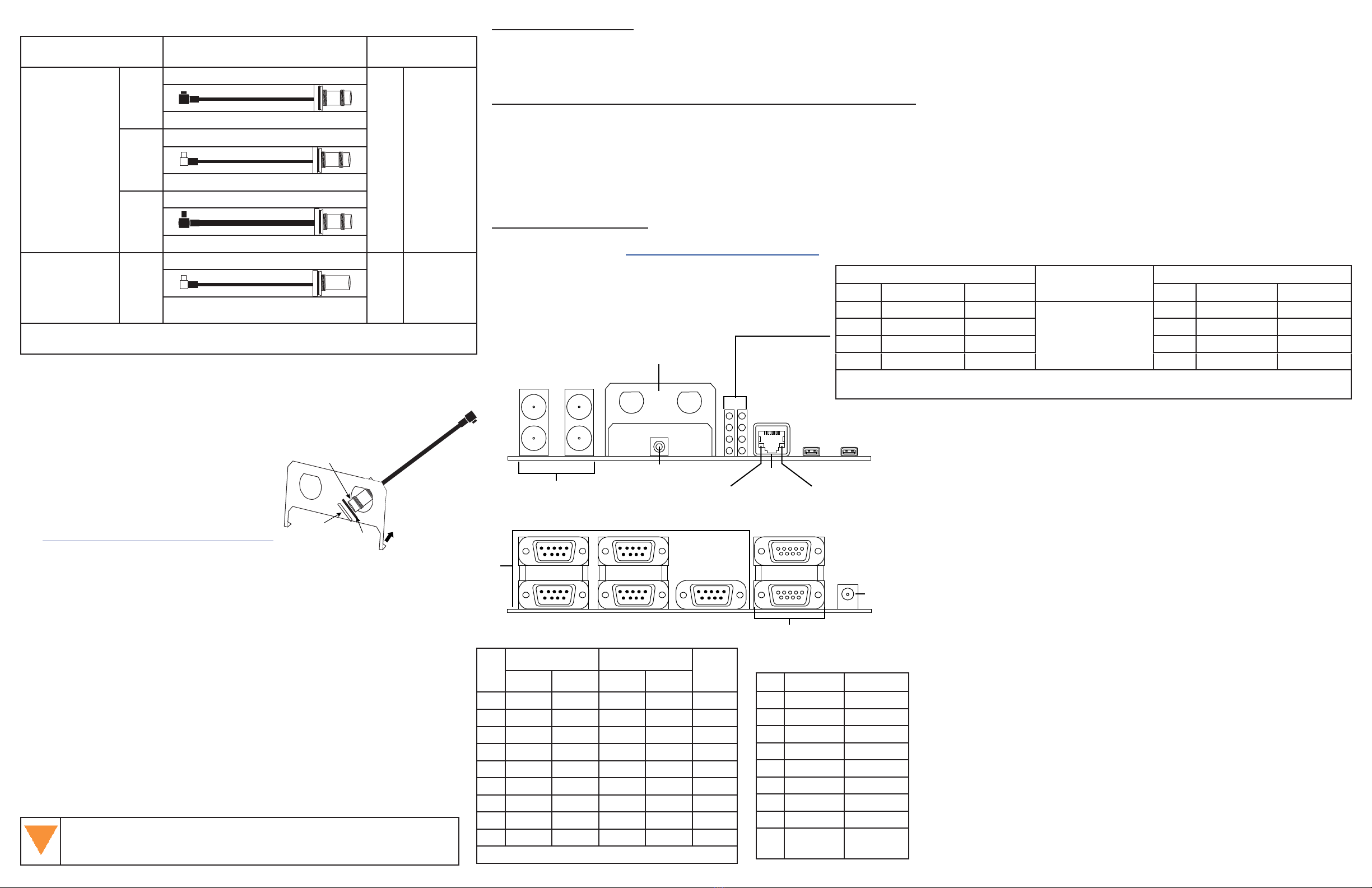
EVENT Ports
2 Position, 50 Ohm BNC
1 GHz Max
OUT2OUT1
IN1 IN2
Reset Button
Press to perform
reset of card
Coaxial Cable Bracket
ANT TNC / EXT OSC BNC
Ethernet
RJ45
10/100 Base-T
USB
Micro-AB
USB1
Green LED
Link/Activity
Yellow LED
Not used
LED Stack
6
4
2
0
7
5
3
1
USB0
COM Ports
DB9, Male
CAN Ports
DB9, Female
CAN0
COM1
COM2
COM3
COM4 COM5
CAN1
DC Power
Coaxial Cable Bracket
Mounted on Dev Board
Nut
Washer
Dev Board
TNC/BNC cable end
Mounting the Coaxial Cable into Bracket
The bracket openings are used to mount and secure the Antenna (ANT) and/or
External Oscillator (OSC) connectors to the Development Board.
1. Remove the top nut and washer from the TNC/BNC end of the coaxial cable.
Set aside.
2. Thread the TNC or BNC end of coaxial cable through the bracket from Dev
Board side to the outside (either opening).
3. Slide the washer and then the nut over the TNC or BNC end of the protrud-
ing coaxial cable and slide up against the external side of the bracket.
4. Hand tighten nut to secure the cable and connector to the bracket.
5. Connect antenna to receiver card or EVENT to the Dev Board.
6. Continue to Installation & Powering Steps section or repeat as needed for
second cable.
Attach the MCX, MMCX or MMBX connector of the coaxial cable(s)
to the receiver BEFORE securing the receiver cards to the Dev Board
with the standos and screws.
External Oscillator
Some applications require greater precision
than that possible with the OEM7 VCTCXO,
in which case you may need to connect the
OEM7 to an external high-stability oscillator,
which may run at either 5 MHz or 10 MHz.
Antenna Selection
Select a quality GNSS antenna, such as one
from NovAtel’s 500 or 800 series. Contact
your NovAtel representative or visit our web
site www.novatel.com/products/gnss-antennas
for a full range of available antenna options.
Installation & Powering Steps
1. Flip the Dev Board upside down. Attach the four provided rubber feet over
the four white circles in each corner of the Dev Board. These provide stabil-
ity for the board.
2. Turn the Dev Board right side up and place on a at stable surface.
3. Ensure the steps listed in the Mounting the Coaxial Cable into Bracket
section are complete before progressing to Step 4.
4. If using, make the connections/attachments for the ANT/OSC cables using
the TNC/BNC end of the coaxial cable and connect to receiver card or Dev
Board as indicated in Coaxial Cable Assembly table.
5. If needed, attach the Interposer card to the Dev Board using the provided
standos and screws as indicated in the Stando Use table on the other
side of this sheet.
For the OEM7600, attach the OEM7600 to the OEM7600 Interposer board
using M3 screws before attaching the Interposer Board to the Dev Board.
6. If required, attach the applicable receiver card to the Interposer card using
the provided standos and screws OR
Attach applicable receiver card directly to the Dev Board using the provided
standos and screws as indicated in the Stando Use table on the other
side of this sheet.
7. If using, connect EVENT end cable to applicable EVENT connector on the
Dev Board. Refer to the Coaxial Cable Assembly table on this page. For
event connector locations, refer to the illustration on the other side of this
sheet.
8. Set external power supply to 9 V to 36 VDC.
9. Set any Slide Switches on the Dev Board and, if using, the Interposer card.
Refer to the Switch Settings tables on the other side of this sheet.
10. Connect any communications equipment to be used.
11. Connect the power cord and plug into external power supply.
Status LED States
Left LED Stack from Top Right LED Stack from Top
LED# Description Color LED# Description Color
6n/a 7n/a
4Status GREEN* 5ME_RDY GREEN
2Status RED* 3POS_VALID GREEN
0ERROR RED 1POWER RED
* LED 2 and 4 represents the receiver card’s onboard LED status (when on at the same time, they represent the
yellow error status code). Search for Status Indicator in the OEM7 online documentation.
Coaxial Cable Assembly (for ANT/OSC/EVENTS)
Connect this end as indi-
cated below
Connect this end as
indicated below
Attach to
Antenna port of
receiver card
MCX
OEM719/OEM719A
TNC GNSS
Antenna
#01019429
MMCX
OEM729/OEM729R/OEM7600
#01019430
MMBX
OEM719B/OEM7700/OEM7720
#01019599
Attach to Exter-
nal Oscillator on
receiver card or
Event lines on
Dev Board
MMCX
OEM729/OEM729R/Dev Board
BNC
OSC
(External
Oscillator)
EVENTS
#01019431
Always connect the coaxial cable to the receiver card prior to attaching to the Dev Board
or Interposer card.
PIN CAN0 CAN1
1 NC NC
2 CAN_L CAN_L
3 GND GND
4 NC NC
5 GND GND
6 GND GND
7 CAN_H CAN_H
8 NC NC
9 12 V CAN
power
12 V CAN
power
PIN
COM1 COM21COM3,
COM4,
COM5
RS-232 RS-422 RS-232 RS-422
1 NC NC NC NC NC
2 RXD1 RX1+ RXD2 RX2+ RXD
3 TXD1 TX1+ TXD2 TX2+ TXD
4 NC NC NC NC NC
5 GND GND GND GND GND
6 NC NC NC NC NC
7 RTS1 TX1- RTS2 TX2- NC
8 CTS1 RX1- CTS2 RX2- NC
9 NC NC NC NC NC
1COM2 RTS/CTS MUX with COM5 TXD/RXD
Warnings and Restrictions
For evaluation only, in Laboratory/Development Environments. The development kit is not nished electrical and electronic equipment (EEE) and is not intended for
consumer use. It is intended solely for use for preliminary evaluation in laboratory/development environments by technically qualied experts who are familiar with the dan-
gers and application risks associated with handling electrical mechanical components, systems, and subsystems. The development kit should not be used as all or part of a
nished end product.
Federal Communications Commission (FCC) and Industry Canada (IC) Notices:
This development kit is designed to allow:
(1) Product developers to evaluate electronic components, circuitry, or software associated with the kit to determine whether to incorporate such items in a nished product
and
(2) Software developers to write software applications for use with the end product. This kit is not a nished product and when assembled may not be resold or otherwise
marketed unless all required FCC and IC equipment authorizations are rst obtained. Operation is subject to the condition that this product not cause harmful interference to
licensed radio stations and that this product accept harmful interference.
(3) This kit generates, uses, and can radiate energy and has not been tested for compliance with the limits of digital devices pursuant to Part 15 of FCC or ICES-003 rules
which are designed to provide reasonable protection against radio frequency interference.
EU Declaration of Conformity
Hereby, NovAtel Inc. declares that the OEM7 Development Kit is in compliance with Directive 2011/65/EU. The full text of the EU declaration of conformity is available at the
following Internet address: www.novatel.com/products/compliance.


