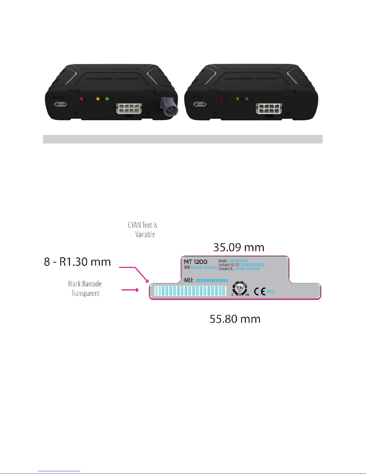
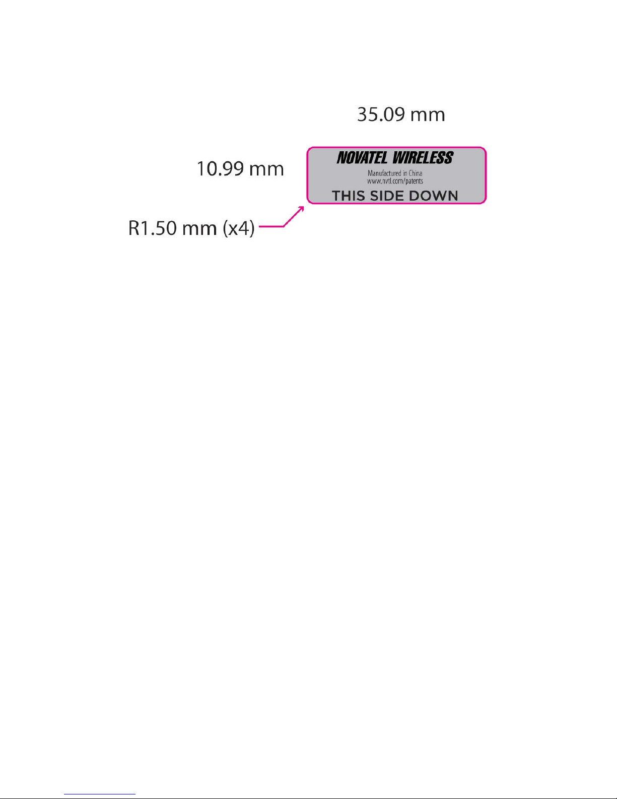
Device Description and Label
Designed for simplicity, flexibility and economy, the MT 1200 combines “tried and true” vehicle tracking
features with an open platform option and a compact device size to deliver an exciting new tracking
solution from Novatel Wireless.
Open Platform
With the open platform option, the compact MT 1200 can host software applications from Telematics
Service Providers (TSPs), ideal for aftermarket solution providers to port their proprietary code. This
open platform is complemented by the MT 1200’s hardware capabilities, including GPS/GLONASS
antenna, digital accelerometer, power management processor, and multiple I/O options.
Smart Agent
First released in 1996, the Novatel Wireless Smart Agent is a powerful software event engine that has
been continually enhanced to accommodate newer and more sophisticated M2M devices and to build
on experience gained through years of Internet of Things (IoT) support. With the Smart Agent option,
the MT 1200 can be programmed to handle precise vehicle tracking needs, such as defining geo-fences
over circular or polygonal areas, detecting harsh cornering or rapid acceleration, waking the device out
of low power sleep mode, generating trip reports, or enabling and disabling remote starts.
Simple Installation
Installing the MT 1200 vehicle tracking solution is simplified because it comes with preinstalled
hardware features that include internal cellular antenna, internal backup battery, and internal
GPS/GLONASS antenna (or external antenna connector for hard-to-reach areas). Installation is further
simplified when used with the available Smartphone app to assist with field installation or diagnosis.
Cloud management (Optional)
With cloud-enabled N4A™ Device Manager, up to 500,000 MT 1200 devices can be easily managed and
monitored around the globe in a cost-efficient and scalable manner. The N4A™ Device Manager features
remote management and monitoring from a central location to configure, monitor, manage, and even
update MT 1200 all over the air.
MT 1200 User Guide 2