NOVO Aqua Flo 475QC Instruction sheet

Canada West
855 Park St.
Unit 1
Regina, SK S4N 6M1
Canada East
490 Pinebush Rd.
Unit 1
Cambridge, ON N1T 0A5
U.S.A.
56 Lightcap Rd.
Pottstown, PA 19464
9760 Mayower Park Drive,
Suite 110
Carmel, IN 46032
4645 McDowell Rd. W
Suite 106
Phoenix, AZ 85035
Installation and Operation Manual
How To Install, Operate and
Maintain Your 475QC Filter System
INSTALLERS: PLEASE READ ALL INSTRUCTIONS BEFORE INSTALLING AND USING THIS SYSTEM.
IT IS RECOMMENDED TO WAIT UNTIL THE ENTIRE SYSTEM IS PRESSURIZED AND RE-CHECK FOR ANY LEAKS
BEFORE LEAVING INSTALLATION SITE.
IT IS NORMAL FOR SOME BLACK CARBON FINES TO APPEAR IN THE WATER WHEN FLUSHING FOR THE
FIRST TIME. THE FIRST 2-3 GALLONS OF FILTERED WATER SHOULD NOT BE USED.

2
Table of Contents
HOW YOUR SYSTEM WORKS 2
BEFORE YOU START 3
TOOLS NEEDED 3
SYSTEM LOCATION 3
INSTALLING THE FILTERS 4
INSTALLING THE FAUCET 4
INSTALLING THE SELFPIERCING INLET SADDLE VALVE 5
INSTALLING THE UNIT 5
INSTALLING TUBING INTO FITTINGS 5
INSTALLING TUBING CONNECTIONS 6
FLOW DIAGRAM 6
PARTS 7
HOW YOUR SYSTEM WORKS
For best results it is recommended to install the lter on a COLD raw water (non-softened) water supply.
The 475 Pro Series systems uses up to three stages of treatment to lter your water:
Stage 1: - SED-10 to remove sand, dirt, sediment
Stage 2: - COC-10 / GAC-10 to remove chlorine, taste & odors, very ne particulates
Stage 3: - UF-10 to reduce lead, VOC, and ne particles down to 0.2 micron
The system is compact and can be installed under the sink or another convenient place close to the faucet. The closer the proximity to the
faucet the better the system ow rate.
Recommended Filter Change Schedule
Your lters require changing on a regular basis. Instructions to change them are on page 8.The schedule below is the minimum recom-
mendation. Depending on your water conditions the lters may need to be changed more often.
Disposable Filters Change Schedule
Sediment (SED-10) Every 12 months
Carbon (COC-10) Every 12 months
Carbon (GAC-10) Every 12 months
Ultra-Filter Every 12 months

2 3
BEFORE YOU START
●
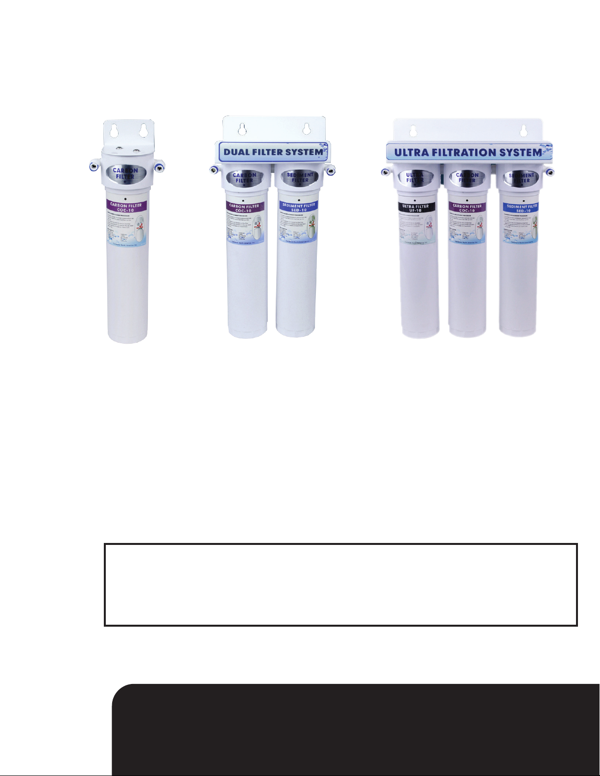
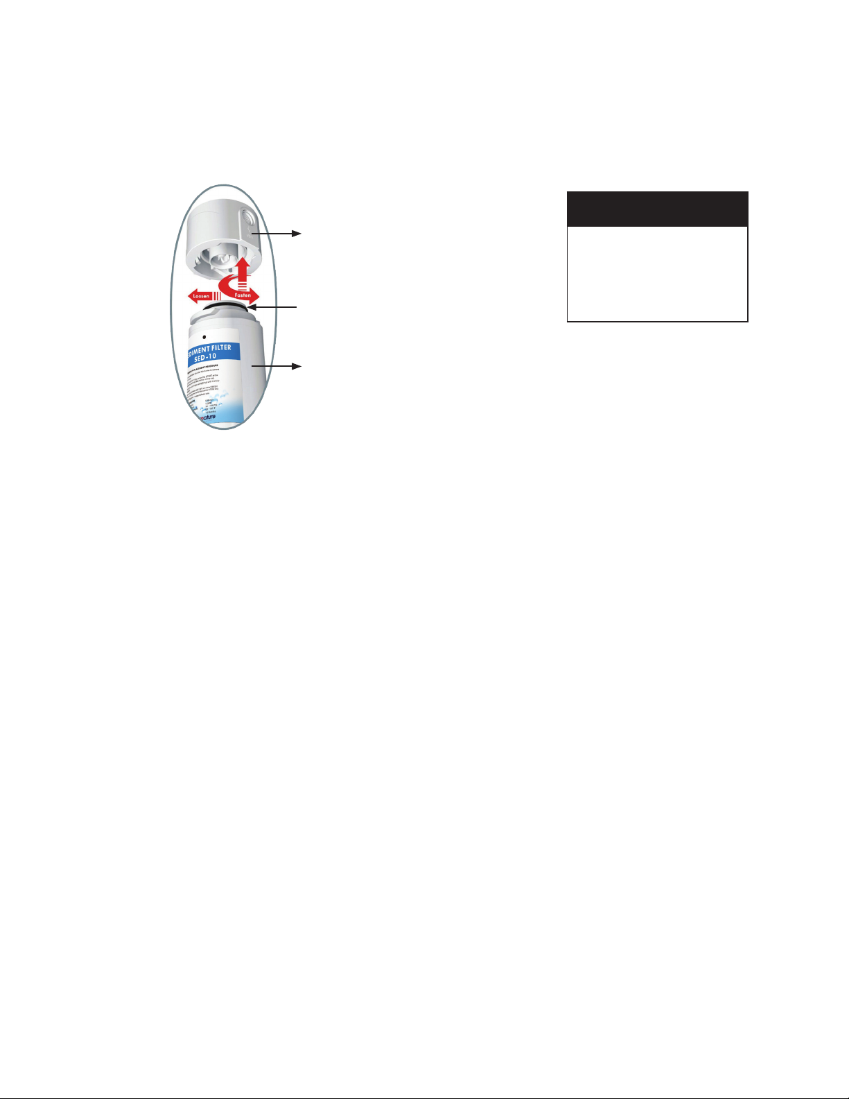
Your system contains lters which must be replaced periodically for proper operation. (Refer to Filter Change Schedule on page 2.)
●
Read all steps and guides carefully before installing and using your RO system. Follow all steps exactly to correctly install.
●
The system is designed to be used on potable water supplies only. If water is non-potable, additional pre-treatment will be required.
●
Do not use for the treatment of water that is visually contaminated (cloudy) or has an obvious contamina-tion source, such as contamination by raw sewage.
●
All plumbing should be done in accordance with local codes and requirements.
●
This system works on water pressures of 20 psi (minimum) to 100 psi (maximum). If your house water pressure is over the maximum, install a pressure
reducing valve in the water supply line to the lter system.
●
Do not install the system outside, or in extreme hot or cold temperatures.Temperature of the water supply to the system must be between 40°F and 100°F. Do
not install on hot water.
SYSTEM LOCATION
Your Filter system may be installed under the sink, in a basement, or other location depending on available space. It is recommended the system be installed
in as close a proximity to the faucet to ensure optimal sys-tem ow rate. If you have a water dispenser and or ice maker in your fridge, your Filter system can be
in-stalled to provide the feed water for these features but you should consult your fridge owners manual for fur-ther information.
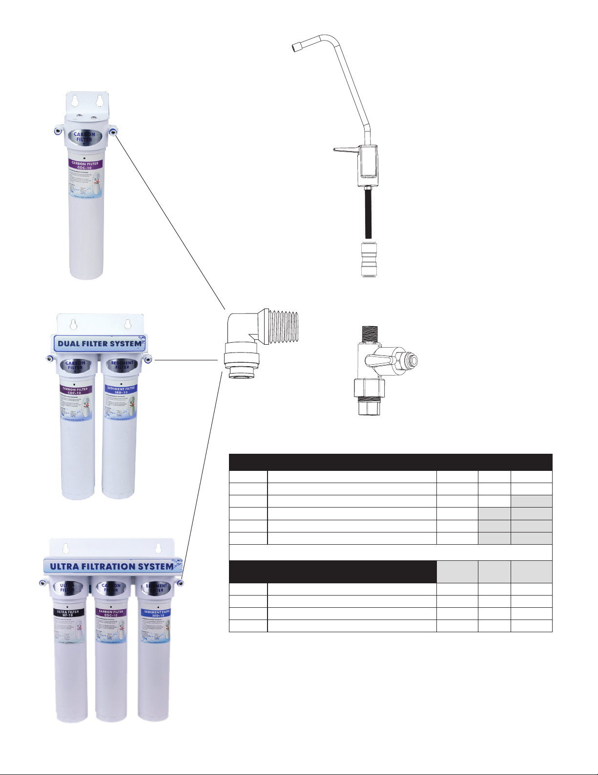
Guidelines for component placement are as follows:
Faucet: - should be placed near the sink where drinking/cooking water is normally required. A 2”at surface is required to mount the faucet if an existing hole
for a second faucet is not available.The thickness of the mounting surface should not exceed 1-1/4”.
Filter unit: - may be mounted on either side of the sink, in a cabinet or heated basement, with nearby access to a potable cold line.
Feed water connection: - is accomplished with a feed water adaptor or self-piercing inlet saddle valve. Lo-cate this assembly as close to the Filter unit as
possible. Connect to a potable, cold water supply line only.
TOOLS NEEDED
The following tools may be necessary, depending on the particular installation.
● 3/8”variable speed electric drill;
1/8”, ¼”, ½”bits
● Center punch and hammer
● Phillips head and flat blade
screw-drivers
● Adjustable wrench
● Teflon tape
● Plastic tube cutter

4
NOTE
It is a good idea to be aware
of where the inlet water
valve is located so that it can
easily be turned off if any
unforeseen problems are
encountered.
INSTALLING THE FILTERS
Your Filter system may be installed under the sink, in a basement, or other location depending on available space. It is recommended the system be installedTo
install the lter simply push it up inside the cap and turn clock wise until the arrow aligns with the center of the cap. To remove the lter reverse the procedure.
The lter head contains an Automatic Shut-o Device.This enables the lters to be changed without shutting the inlet water o. A small amount of water may
leak out during the installation or removal.
INSTALLING THE FAUCET
If the sink has a sprayer it may be disconnected for faucet installation. A pipe cap or plug will be necessary to seal the sprayer connection.
The faucet should be positioned so it empties into the sink and the spout swivels freely for convenience. If sink has a hole that can accommodate the faucet, no
drilling is required. Proceed with mounting the faucet.
Porcelain, Enamel, Ceramic on Metal or Cast Iron Sinks
For porcelain/enamel sinks marble or granite counter tops refer to Manufacturer/Supplier for proper drilling instructions.
Installation procedures for stainless steel sinks
Recommended tools:
Automatic Shut o
Water Device
Use the silicone grease provided
to lubricate this o-ring
Change Filter in
seconds without
Tools
● Center punch
● Variable speed drill
● High speed drill bits
● Protective gloves & eye protectors
To make the faucet mounting hole (if sprayer or second hole is not used), check below to make sure the drill does not interfere with anything below the sink.
Center punch a small indent at the desired faucet location. (2”at surface is required, not exceeding 1-1/4”in thickness). Drill the 1/8”pilot hole. Drill the ½”hole
for the faucet shank to t through. Clean up sharp edges.
Mounting the Faucet
1. Disassemble hardware from the threaded nipple, except for chrome base plates and rubber washers.
2. Feed the threaded nipple through sink or counter mounting hole and orient the faucet. From below sink or counter, assemble the flat washer and hex nut on
threaded nipple and tighten by hand. After checkingfaucet orientation, tighten with a wrench until secure.

4 5
NOTE
THE UNIT MUST BE INSTALLED BY
HANGING THE BRACKET ON THE
WALL SO THAT THERE IS NO WEIGHT
ON THE FILTERS. THE SYSTEM IS NOT
DESIGNED OR INTENDED TO SIT ON
THE FLOOR WITH THE WEIGHT
SUPPORTED BY THE REPLACEABLE
FILTER CARTRIDGES
INSTALLING THE UNIT
When installed under a sink the unit is normally mounted to the right or left sink cabinet sidewall. It is sug-gested to locate the system where it can be easily
accessed or even removed o the hanging screws and pulled back out from the sink to change the lters.
1. Locate the unit in the desired position. Make sure it is at least 3”off the floor. Level it and mark the loca-tion of mounting screws.
2. Install the screws. Leave 1/4”of the screw head out from the wall.
3. Install the mounting bracket slots over the screws and hang the unit.
INSTALLING TUBING INTO FITTINGS
Step 1 Cut the tube square and remove burrs
and sharp edges. Ensure that the out-side
diameter is free from score marks. For soft
or thin walled plastic tubing we
recommend the use of a tube insert.
Step 2 Push the tube into the fitting and up to
the tube stop.
Step 3 Pull on the tube to check that it is secure.
Test the system before use.

6
T Adapter
Cold
Water
Supply
CAUTION!
The Adapter valve should
be connected to cold water
supply only. Connection to
hot watersupply will damage
the system and will void all
warranty.
FLOW DIAGRAMS
INSTALL T ADAPTER VALVE ON WATER SUPPLY
FAUCET
INLET WATER
SUPPLY
T ADAPTER

6 7
475 QC Series Filter Systems
PART # DESCRIPTION Filter 1 Filter 2 Filter 3
20010201 475QC-3 TRIPLE STAGE ULTRA FILTER SED UF COC
20010202 475QC-2 DOUBLE STAGE DUAL FILTER SED COC
20010203 475QC-1C SINGLE STAGE COCONUT CARBON FILTER COC
20010204 475QC-1S SINGLE STAGE SEDIMENT FILTER SED
20010205 475QC-1G SINGLE STAGE GAC FILTER GAC
475 QC Series Replacement Filters
PART # DESCRIPTION MICRON FLOW
RATE
CAPACITY
(GALLONS)
65010086 SEDIMENT FILTER SED-10 BLUE (475 Q SERIES) 5 1 GPM 900
65010088 CARBON FILTER COC-10 PURPLE (475 Q SERIES) 10 1 GPM 1,500
65010089 CARBON FILTER GAC-10 YELLOW (475 Q SERIES) - 0.7 GPM 1,500
65010093 ULTRA FILTER UF-10 BLACK (475 Q SERIES) 0.2 0.7 GPM 1,500
FAUCET
87511
ELBOW CI
CI480822W
T ADAPTER
60095649
FAUCET ADAPTER
PP3208U7W
QC-1
QC-2
QC-3
PARTS

Canature WaterGroup™
855 Park Street,Unit 1
Regina, SK. S4N 6M1
Canada
Toll Free: (877) 288-9888
USA Office:
9760 Mayflower Park Drive, Suite 110
Carmel, IN. 46032
USA
Toll Free: (877) 288-9888
80150374.2021-12-13
Table of contents
Other NOVO Water Filtration System manuals
Popular Water Filtration System manuals by other brands

ProMinent
ProMinent ProMaqua Bello Zon CDLb Series operating instructions

Wave
Wave wavebrite SMART Installation & operating instructions

Omnifilter
Omnifilter LN3 Series A installation instructions

FSA
FSA GT1-26-4 quick start guide

Anchor
Anchor AF-5002 Installation & setup guide

Luminator
Luminator BLACKOMB LB6-02 A Series owner's manual

Philips
Philips Saeco AquaClean CA6903 manual

Aquascape Pro
Aquascape Pro Signature Series 1000 Instruction and maintenance manual

Katadyn
Katadyn MyBottle manual

Hydrotech
Hydrotech 765 Quick setup manual

Amway
Amway eSpring Easy installation guide

Perfect Water Technologies
Perfect Water Technologies Home Master HMF1C Installation & service manual