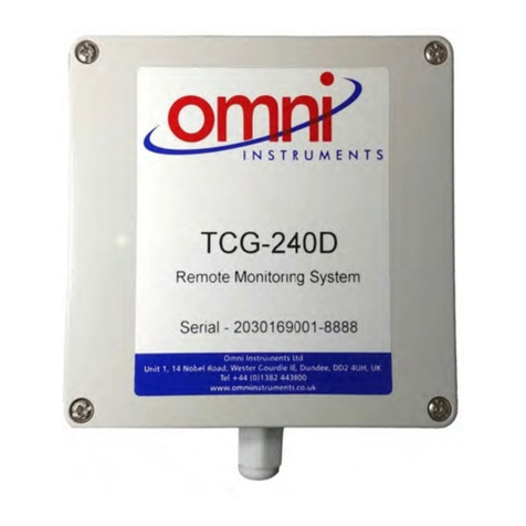
novocure MyLink OTU5000 User manual

QSD-QR-026 CA(EN) Rev01 MyLink User Manual
Page 1/19
MyLink™ User Guide
Model # OTU5000
Making data collection from the Electric Field Generator with MyLink

QSD-QR-026 CA(EN) Rev01 MyLink User Manual
Page 2/19
Contents
1. About MyLink – Device Description .......................................................................................................... 3
Intended Purpose...................................................................................................................................... 3
Intended Users and Use Environment ...................................................................................................... 3
Contraindications, Warnings, Precautions and Notices............................................................................ 3
WARNINGS ........................................................................................................................................... 3
PRECAUTIONS....................................................................................................................................... 3
NOTICES ................................................................................................................................................ 3
2. Principles of Operation ............................................................................................................................. 3
3. Overview of MyLink .................................................................................................................................. 4
4. Glossary of Symbols .................................................................................................................................. 5
5. General Information ................................................................................................................................. 7
6. Instructions ............................................................................................................................................... 7
7. Environmental Conditions....................................................................................................................... 11
Conditions for operation......................................................................................................................... 11
Data Integrity .......................................................................................................................................... 11
Storage .................................................................................................................................................... 11
Transportation ........................................................................................................................................ 11
Cleaning................................................................................................................................................... 11
8. Expected Product Life............................................................................................................................. 11
9. Disposal................................................................................................................................................... 11
10. MyLink™ troubleshooting tips .............................................................................................................. 12
11. Assistance and Information ................................................................................................................. 15
12. Appendix A – Applicable Standards.................................................................................................... 15
13. Appendix B - Electrical Specifications and Cellular Network Specifications ...................................... 15
14. Appendix C - Emitted radiation and electromagnetic compatibility ................................................. 16
This manual is intended for patients receiving Tumor Treating Fields therapy using the following electric
field generator:
-Optune device (TFH9100)
Please note: The color of the front face of your device may look different from the color shown in the
diagram

QSD-QR-026 CA(EN) Rev01 MyLink User Manual
Page 3/19
1. About MyLink – Device Description
Intended Purpose
MyLink enables the patient to upload the electric field generator’s log files to a remote secured
Novocure server from the comfort of his/her home.
Intended Users and Use Environment
The device is intended for use by the adult patient or their caregivers in the home health care
environment.
Contraindications, Warnings, Precautions and Notices
WARNINGS
Warning!—All servicing procedures must be performed by qualified and trained personnel. Attempting
to open and service your MyLink may result in an electric shock by touching the inner parts of the
equipment. It could also cause damage to the unit.
Warning!—No modification of this equipment is allowed.
PRECAUTIONS
Caution — MyLink is to be used with the electric field generators listed on page 2 only.
NOTICES
Notice — Your MyLink unit is using a cellular network for its operation. If you are trying to use it in a
non-cellular reception environment, the unit will not work properly.
2. Principles of Operation
MyLink is a standalone technical unit which enables the easy upload of data from the electric field
generator to a remote secured Novocure server from the comfort of the patient’s home. The data
uploaded contains only information about the usage of the device and any errors, it does not contain
identifiable patient information
MyLink connects to the electric field generator to download the data log files to an internal memory and
then uploads the downloaded data to the remote secured Novocure server using the cellular network.
Data integrity is maintained at all times even when the data transfer stops, loses signal or cannot be
completed.

QSD-QR-026 CA(EN) Rev01 MyLink User Manual
Page 4/19
The download time should take 1-3 minutes while the upload time takes up to 15 minutes with a good
connection. The data download mode must be finished before the upload mode can start. The
separation between the two modes is done by disconnecting the data cable from the electric field
generator.
3. Overview of MyLink
MyLink is comprised of an enclosure incorporating a cellular modem and custom software, a cable that
connects the unit to the electric field generator and a power cord. It is powered from AC mains and is
equipped with an internal backup battery
On/off indicator
Download indicator
Upload indicator
Electric field generator
MyLink (front)
MyLink (back)

QSD-QR-026 CA(EN) Rev01 MyLink User Manual
Page 5/19
4. Glossary of Symbols
Follow instructions for use
Manufacturer information: Novocure GmbH
Model number
Catalogue number
Serial Number
Date of Manufacture
Caution - Consult the instructions for use for important cautionary information
WEEE; Waste Electrical and Electronic Equipment; Contact technical support to
coordinate disposal; Contact technical support to coordinate disposal
Protect from heat and radioactive sources
MyLink unit should be kept away from extreme heat and sources of radiation
IP22
Ingress Protection: Protects persons against access to hazardous parts with fingers.
Protects the equipment inside the enclosure against ingress of solid foreign objects of
12.5 mm in diameter or greater. Protects the equipment inside the enclosure against
ingress of vertical falling water drops when enclosure is tilted up to 15°.
Do not wet the device
For indoor use only
Class II electrical equipment
Do not expose to temperatures below -5°C or above 40°C
REF
SN

QSD-QR-026 CA(EN) Rev01 MyLink User Manual
Page 6/19
Do not expose to humidity below 15% or above 93%
Fragile
– handle with care
Industry Canada
Power ON / OFF switch
On/off indicator
Download indicator
Upload indicator
MET mark for electrical safety released by an accredited lab

QSD-QR-026 CA(EN) Rev01 MyLink User Manual
Page 7/19
5. General Information
You should download your usage data from your electric field generator to the MyLink unit every month
and when in need of technical assistance.
6. Instructions
1. Plug the power cord into the back of the MyLink unit and connect the
unit to a wall outlet.
2. Locate the main power switch on the back of the MyLink unit. Press
the switch to “I” to power up MyLink.
Result: The indicator on the top of your MyLink unit will blink
green, indicating MyLink is performing a self-test. Wait until the light
stops blinking and “turns steady green”.
3. Stop TTFields treatment by pressing the TTFields button on your
electric field generator, and unplug the connection cable from your
electric field generator.
4. Open the lid of your MyLink . Release enough cable to connect to the
electric field generator.

QSD-QR-026 CA(EN) Rev01 MyLink User Manual
Page 8/19
5. Connect your MyLink unit to the electric field generator connection
port.
Note: To ensure proper connection, align the arrow on the cable of
your MyLink unit with the arrow on the socket on the front panel of
the electric field generator.
6. Make sure your electric field generator is on.
The “POWER” indicator on the front of the electric field generator is
illuminated in green.
If a battery is installed and the plug-in power supply is not in use, the
“BATTERY” indicator is also illuminated in green.
7. Download the usage data from your electric field generator.
Result: The indicator on the top of your MyLink unit will blink
green. This indicator means the MyLink unit is downloading your
usage data from your electric field generator.
Important: After a few minutes, the indicator stops blinking
and turns steady green, indicating that the download process is
complete. Your MyLink unit will beep to indicate completion of the
download process. The beeps will continue until you disconnect the
MyLink cable from your electric field generator (see next step).
Electric field generator

QSD-QR-026 CA(EN) Rev01 MyLink User Manual
Page 9/19
Important: MyLink will beep for both successful and failed data
collection. This beeping notification signal tells you to disconnect the
MyLink unit and go back on treatment, even if data collection failed.
In the case of download failure, the indicator of your MyLink
unit will show red. For more information, see the MyLink
troubleshooting tips section of this manual.
8. Disconnect the MyLink unit cable from the electric field generator.
Result: The beeping notification signal from the MyLink unit will stop.
9. Turn the electric field generator to OFF by switching the power
switch to “O”. Wait a few seconds until the indicator “POWER” turns
off and switch the power back on to “I” on the electric field generator.
10. Plug the electric field generator connection cable into the device
and push the TTFields therapy ON/OFF button to resume TTFields
treatment.
Result: The blue indicators surrounding the TTFields ON/OFF button
will light up and remain on for as long as the treatment continues.
11. Automatic upload of the usage data from MyLink to the remote
secured server.
Once starts blinking green, the MyLink unit is uploading your
treatment data directly to the remote secured server.
Wait up to 15 minutes for the uploading process to be completed.

QSD-QR-026 CA(EN) Rev01 MyLink User Manual
Page 10/19
12. Once all 3 MyLink indicator lights stop blinking and turn steady
green, the upload has been successful.
The data is now available for your Novocure representative.
13. Turn off your MyLink unit using the main power switch on the
back.
Note: The unit may take up to 10 seconds to turn off.

QSD-QR-026 CA(EN) Rev01 MyLink User Manual
Page 11/19
7. Environmental Conditions
Conditions for operation
Mainly for home use.
For indoor use only.
Data Integrity
The integrity and availability of the usage data are assured:
•Usage data remain in the electric field generator until MyLink “confirms” all data have been
received intact (successful download), and
•Usage data remain in your MyLink unit until the remote secured server “confirms” all data have
been received intact (successful upload).
Storage
The MyLink unit should be stored in a dry area away from extreme temperature conditions.
Transportation
Traveling with MyLink
Transportation of MyLink should be possible using air/ground transportation in weather-protected
conditions as specified below:
•Temperature range: -5oC to +40oC
•No direct exposure to water.
Cleaning
Cleaning: all external components can be periodically cleaned with a damp cloth to remove dust and
regular soil. Avoid using detergents or soaps.
8. Expected Product Life
The MyLink unit’s expected service life is 5 years.
9. Disposal
Please contact your Device Support Specialist for proper disposal. Do not throw in the trash.

QSD-QR-026 CA(EN) Rev01 MyLink User Manual
Page 12/19
10. MyLink™ troubleshooting tips
Follow the instructions provided if your MyLink is experiencing the following:
The On/Off ( ) Indicator is OFF
1. Make sure your MyLink unit power cord is plugged into the AC port and a standard power
source (wall outlet).
2. Make sure your MyLink unit power switch is in the “I” position. If not,push the power switch
to ”I”.
3. If the indicator is still OFF, please contact nCompass for further support. nCompass
contact details can be found in Section 11 or on the last page of this manual.
The On/Off ( ) Indicator is RED
1. Push the power switch of your MyLink unit to ”O”.
2. Wait a few seconds until the indicator turns OFF.
3. Then, switch your MyLink unit back to ON (power switch in “I” position).
4. If the indicator is still RED, please contact nCompass for further support.
The Download ( ) Indicator does not turn ON
1. Make sure the indicator on your MyLink unit is green.
2. Make sure your electric field generator is connected to your MyLink unit, and that the arrow
on the cable of your MyLink unit is aligned with the arrow on the socket on the front panel
of the electric field generator.
3. Make sure your electric field generator is switched ON. If not, push the device power switch
to ”I”.
4. If the indicator is still OFF, please contact nCompass for further support.
The Download ( ) Indicator is RED
This indicates that the transfer of data from your electric field generator to your MyLink unit was
unsuccessful.
PART A: Free up storage space on your MyLink unit for data transfer:
1. Disconnect your MyLink unit cable from electric field generator.
2. Switch your MyLink unit to OFF (power switch in “O” position). It may take a few seconds for
the indicators to turn OFF.
3. Switch your MyLink unit to ON (power switch in “I” position).
4. Wait for the indicator to turn steady green.
5. Wait for about 20 seconds and then check if the indicator starts flashing green.

QSD-QR-026 CA(EN) Rev01 MyLink User Manual
Page 13/19
If it stays OFF, continue with “PART B.”
6. Wait for the indicator to be steady green.
7. Switch your MyLink unit to OFF (power switch in “O” position). It may take a few seconds for
the indicators to turn OFF.
8. Switch your MyLink unit to ON (power switch in “I” position).
9. Wait for the indicator to turn steady green.
10. Connect your MyLink unit cable to the electric field generator.
11. Power ON your electric field generator.
12. Make sure the indicator is flashing green.
13. Wait until it turns to steady green.
14. NOTE: If the indicator turns steady green the failure is fixed. If the failure is still
occurring ( indicator stays red), please contact nCompass® for further support.
PART B: If there is enough storage space on your MyLink unit:
1. Make sure the indicator of your MyLink unit is steady green.
2. Make sure your MyLink unit cable is properly connected to the electric field generator.
3. Switch your MyLink unit to OFF (power switch in “O” position). It may take a few seconds for the
indicators to turn OFF.
4. Switch your electric field generator to OFF (power switch in “O” position).
5. Switch your electric field generator back to ON (power switch in “I” position).
6. Then, switch your MyLink unit back to ON (power switch in “I” position).
7. Wait a few seconds until the indicator turns to steady green.
8. Make sure the indicator is flashing in green, and wait a few minutes while your MyLink
unit is downloading data.
9. You will know the data download to your MyLink unit is successful when:
a. The indicator stops flashing and is steady green.
b. Your MyLink unit is beeping.
10. If the indicator stays red in one of above steps, please contact nCompass for further
support.
The Upload ( ) Indicator does not turn ON
This indicates that your data failed to be uploaded from your MyLink unit to the remote secured server.
1. Make sure that both the and the indicators are steady green.

QSD-QR-026 CA(EN) Rev01 MyLink User Manual
Page 14/19
2. Make sure your MyLink unit is disconnected from your electric field generator.
3. If the indicator stays OFF, please contact nCompass for further support.
.
The Upload ( ) Indicator is RED
This indicates that your data was unsuccessfully uploaded from your MyLink unit to the remote secured
server.
1. Make sure your MyLink unit has cellular reception (e.g. you are not in a basement).
2. Make sure your MyLink unit cable is disconnected from your electric field generator.
3. Switch your MyLink unit to OFF (power switch in “O” position). It may take a few seconds
for the indicators to turn OFF.
4. Switch your MyLink unit back to ON (power switch in “I” position).
5. Wait about 20 seconds and check the indicator status:
a. - Steady green
b. - Steady green or OFF
c. - Flashing green
NOTE: If the data was already downloaded to your MyLink unit, then the indicator will
be OFF.
6. Make sure the indicator is flashing in green and wait for the data to complete
uploading.
7. You will know the data upload to the remote secured server is successful when the
indicator stops flashing and turns to steady green.
8. If the indicator stays red in one of above steps, please contact nCompass for further
support.
NOTE: MyLink will attempt to upload data for 15 minutes. You will know the upload of data has failed
when the indicator becomes steady red.

QSD-QR-026 CA(EN) Rev01 MyLink User Manual
Page 15/19
11. Assistance and Information
TECHNICAL SUPPORT
For technical support, contact Novocure via phone 1.866.320-2006 or email support@novocure.com
12. Appendix A – Applicable Standards
The MyLink unit complies with UL/CSA-C22.2 No.62368-1:2014 Audio/Video, Information and
Communication Technology Equipment - Part 1: Safety Requirements;
Industry Canada IC certification:
MyLink contains equipment certified under IC: 2417C-MC7304.
13. Appendix B - Electrical Specifications and Cellular Network Specifications
MyLink is considered class II equipment according to UL/CSA-C22.2 No.62368-1. It is connected to a
standard power outlet and uses the cellular network.
Electrical rating
100-240VAC, 50/60Hz, 0.5A max.
7.2VDC, 3350mAh from internal rechargeable battery

QSD-QR-026 CA(EN) Rev01 MyLink User Manual
Page 16/19
14. Appendix C - Emitted radiation and electromagnetic compatibility
MyLink is intended for use in a home healthcare environment (such as domiciles [residences, homes,
nursing homes], hotels, hostels and pensions).
Warning - Use of this equipment adjacent to or stacked with other equipment should be avoided
because it could result in improper operation. If such use is necessary, this equipment and the other
equipment should be observed to verify that they are operating normally.
Warning - The use of accessories, transducers and cables other than those specified or provided by the
manufacturer of this equipment could result in increased electromagnetic emissions or decreased
electromagnetic immunity of this equipment and result in improper operation.
Warning - Portable and mobile RF communications equipment (including peripherals such as antenna
cables and external antennas) should be used no closer than 30 cm to any part of MyLink including
cables specified by the manufacturer. Otherwise, degradation of the performance of this equipment
could result.
MyLink needs special precautions regarding electromagnetic compatibility (EMC) and needs to be
installed and put into service according to the EMC information provided below.
Table 1 – Guidance and MANUFACTURER’S declaration – ELECTROMAGNETIC EMISSIONS – for all ME
EQUIPMENT and ME SYSTEMS
Emissions test
Compliance
Electromagnetic environment - guidance
RF emissions
CISPR 11 Group 1
MyLink uses RF energy only for its internal function. Therefore, its
RF emissions are very low and are not likely to cause any
interference in nearby electronic equipment
RF emissions
CISPR 11 Class B
MyLink is suitable for use in all establishments, including domestic
establishments and those directly connected to the public low-
voltage power supply network that supplies buildings used for
domestic purposes.
Harmonic emissions
IEC 61000-3-2 Class A
Voltage
fluctuations/flicker
emissions
IEC 61000-3-3
Complies

QSD-QR-026 CA(EN) Rev01 MyLink User Manual
Page 17/19
Table 2 – Guidance and MANUFACTURER’S declaration – ELECTROMAGNETIC IMMUNITY – for all ME
EQUIPMENT and ME SYSTEMS
Immunity test IEC 60601 level Compliance level
Electromagnetic environment -
guidance
Electrostatic discharge
(ESD), IEC 61000-4-2
8 kV contact
15 kV air
8 kV contact
15 kV air
Floors should be wood, concrete or
ceramic tile. If floors are covered with
synthetic material, the relative
humidity should be at least 30 %.
Electrical fast
transient/burst,
IEC 61000-4-4
2 kV for power supply
lines
1 kV for SIP/SOP lines
2 kV for power
supply lines
Mains power quality should be that of
a typical commercial or hospital
environment
Surge, IEC 61000-4-5
1 kV line to line
2 kV line to earth
1 kV line to line
2 kV line to earth
Mains power quality should be that of
a typical commercial or hospital
environment.
Voltage dips and
interruptions on
power supply input
lines
IEC 61000-4-11
0 % UT for 0,5 cycle
0 % UT for 1 cycle
70 % UT for 25/30
cycles
0 % UT for 250/300
cycles
0 % UT for 0,5 cycle
0 % UT for 1 cycle
70 % UT for 25/30
cycles
0 % UT for 250/300
cycles
Mains power quality should be that of
a typical commercial or hospital
environment. If the user of the
equipment requires continued
operation during power mains
interruptions, it is recommended that
the equipment be powered from an
uninterruptible power supply or a
battery.
Power frequency
magnetic field,
IEC 61000-4-8
30 A/m 30 A/m
Power frequency magnetic fields
should be at levels characteristic of a
typical location in a typical commercial
or hospital environment.
NOTE: U
T
is the AC mains voltage prior to application of the test level.

QSD-QR-026 CA(EN) Rev01 MyLink User Manual
Page 18/19
Table 3 – Guidance and MANUFACTURER’S declaration – ELECTROMAGNETIC IMMUNITY – for HOME
HEALTHCARE ENVIRONMENT ME EQUIPMENT and ME SYSTEMS
Immunity test
IEC 60601 level
Compliance level
IEC 61000-4-6
Conducted RF
3 Vrms
150 kHz to 80 MHz
6 Vrms in ISM bands (6.765 MHz to 6.795 MHz; 13.553 MHz to 13.567
MHz; 26.957 MHz to 27.283 MHz; and 40.66 MHz to 40.70 MHz) and
amateur bands (1.8 MHz to 2.0 MHz, 3.5 MHz to 4.0 MHz, 5.3 MHz to
5.4 MHz, 7 MHz to 7.3 MHz, 10.1 MHz to 10.15 MHz, 14 MHz to 14.2
MHz, 18.07 MHz to 18.17 MHz, 21.0 MHz to 21.4 MHz, 24.89 MHz to
24.99 MHz, 28.0 MHz to 29.7 MHz and 50.0 MHz to 54.0 MHz)
[V] = 3 Vrms
[V] = 6 Vrms
IEC 61000-4-3
Radiated RF
10 V/m
80 MHz to 2.7 GHz
[E] = 10 V/m
Proximity fields
from RF wireless
communications
equipment
385 MHz
27 V/m
450 MHz
28 V/m
710 MHz
9 V/m
745 MHz
780 MHz
810 MHz
28 V/m
870 MHz
930 MHz
1720 MHz
28 V/m
1845 MHz
1970 MHz
2450 MHz
28 V/m
5240 MHz
9 V/m
5500 MHz
5785 MHz

QSD-QR-026 CA(EN) Rev01 MyLink User Manual
Page 19/19
Novocure GmbH, Business Village
D4, Park 6/Platz 10
6039 Root, Switzerland
©2022 Novocure. All rights reserved. nCompass, MyLink, and Novocure are
trademarks of Novocure
Other manuals for MyLink OTU5000
1
Table of contents
