This installation manual must be given to the customer and kept safely during the entire period of use!
2
EN
General instructions
• Please read the installation manual
completely before using the product for
the first time! Take note of the comments
and comply with the safety notices and
warnings!
Make sure that all generally acknowledged
legal and other binding regulations for the
prevention of accidents and protection of the
environment, national regulations and ack-
nowledged engineering and technical rules
for safe and correct execution of the work
are observed.
• Check that the fasteners and fixing
materials provided are suitable for the site
conditions. Only use suitable fasteners
and fixing materials.
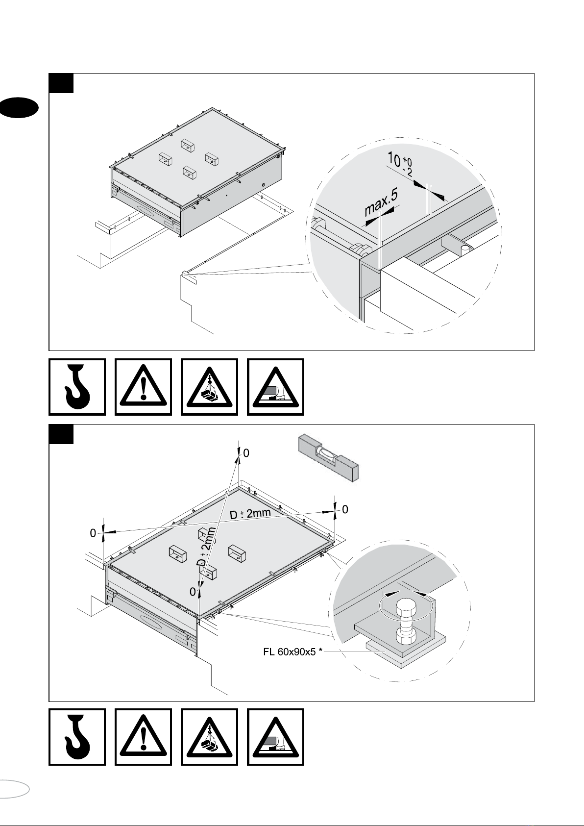
• Perform each step in sequence in
accordance with the installation drawings!
• Only use proper and suitable tools!
• Only work on the leveller when it has
been made non-operational.
• Failure to observe these precautions
may result in serious injury and material
damage!
• The components that are to be used are
manufactured from high-grade, durable
and solid materials. Even so, care must
be taken during installation in order to
avoid damage.
• If parts suffer damage, always replace
them with OEM parts. If you fail to do so,
correct operation of the leveller can no
longer be guaranteed! Furthermore,
this voids the warranty!
Check the following before installation:
Check the following items before installation:
• Does the electrical supply that is available
correspond to the requirements for the
leveller?
• Are suitable cables and fuses available?
• In the case of models that are to be
installed in a prepared pit: Does the pit
correspond to the relevant installation
drawings and has an empty conduit
measuring 70 mm in diameter been
provided to allow insertion of the cable?
Only start installation work if all of the
conditions are satisfied.
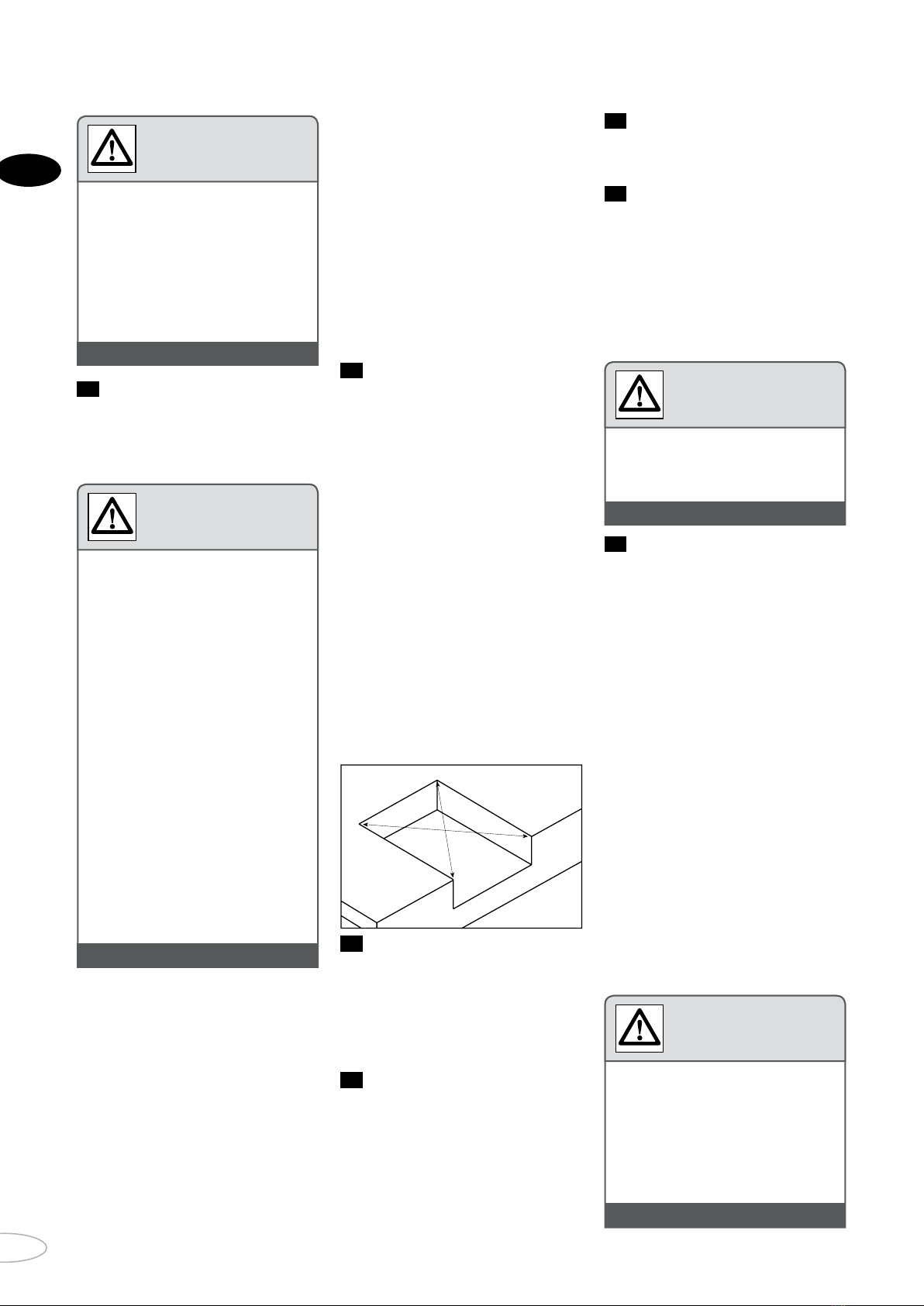
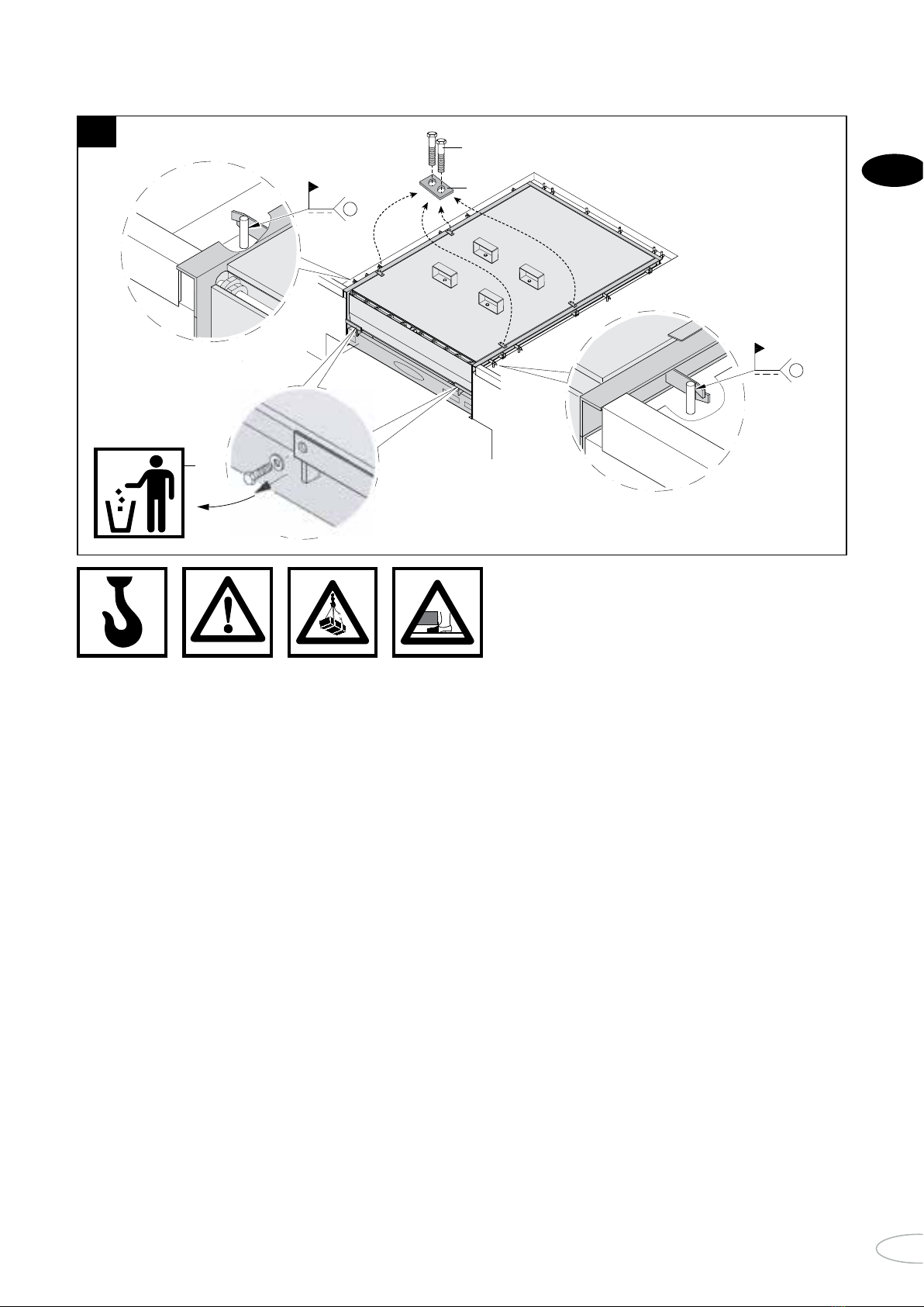
To check dimensional accuracy, measure
the length and width of the pit, the height of
the front and rear sides and the diagonals.
The length of the diagonals (X) may not differ
from each other by more than 10 mm.
Instruction: The leveller must be installed so
that it is perfectly horizontal across its
width. If not, leveller operation may be
adversely affected. There is also a risk of
damage to the leveller.
Tools required for installation
You require the following tools for the instal-
lation work:
• ESAB caddy 200 (5¬200A) welder (typical
example).
• ESAB OK 48.00 3.25 welding rod (typical
example).
Lifting equipment
• Forklift truck: Lifting capacity of at least
35 kN, fork length 2000 mm, or
• Crane: Lifting capacity of at least 35 kN
in the area where work must take place.
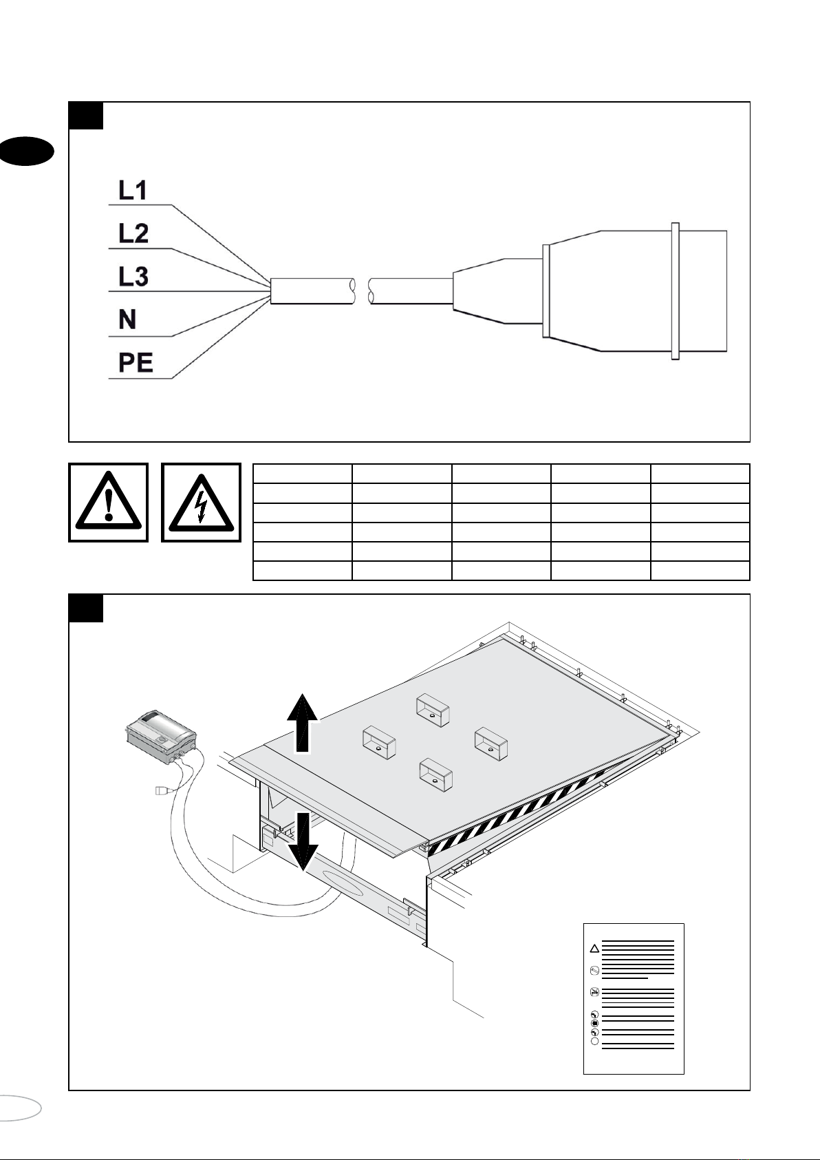
Electrical connections
• Cable: 7 x 0.75mm²
• Motor cable: 4 x 1.5mm²
Functional check
• Check all operating modes of the level-
ler upon completion of the installation
work. To do so, use the leveller test
report.
• Fill out the test report truthfully and
sign the entry.
• After doing so, hand this installation
manual together with the other docu-
ments to the customer.
Commissioning
• The leveller may only be used for the
first time after handing over the decla-
ration of conformity.
• Give the users instruction in how to
operate the leveller. Do not allow third
parties (e.g. visitors) to operate the leveller.
• This installation manual must be given
to the customer and kept safely during
the entire period of use!
• Do not make any changes to the software
for the programmable control unit.
• Changes or additions to the product that
has been delivered may only be made by
the supplier.
• The manufacturer is not liable for
damage caused by non-observance of
the installation manual or improper use.
• Please note that the valid regulations
require the leveller to be inspected by an
expert once a year.
• Maintenance must be performed each
year or every 5000 cycles.
2. General instructions
A malfunctioning leveller may cause
personal injury and material damage to
goods. Only use the leveller when in
proper operating condition.
Warning
++ WARNING +++ WARNING +++ WARNING ++
Movements performed by the leveller
may cause injury to people and damage
to goods.
• Make sure that no people or objects
are in the vicinity of the leveller
when it is moving.
• Never use the leveller to raise people
or objects.
Warning
++ WARNING +++ WARNING +++ WARNING ++
2.7
2.1
2.5
2.6
2.4
2.2
2.3
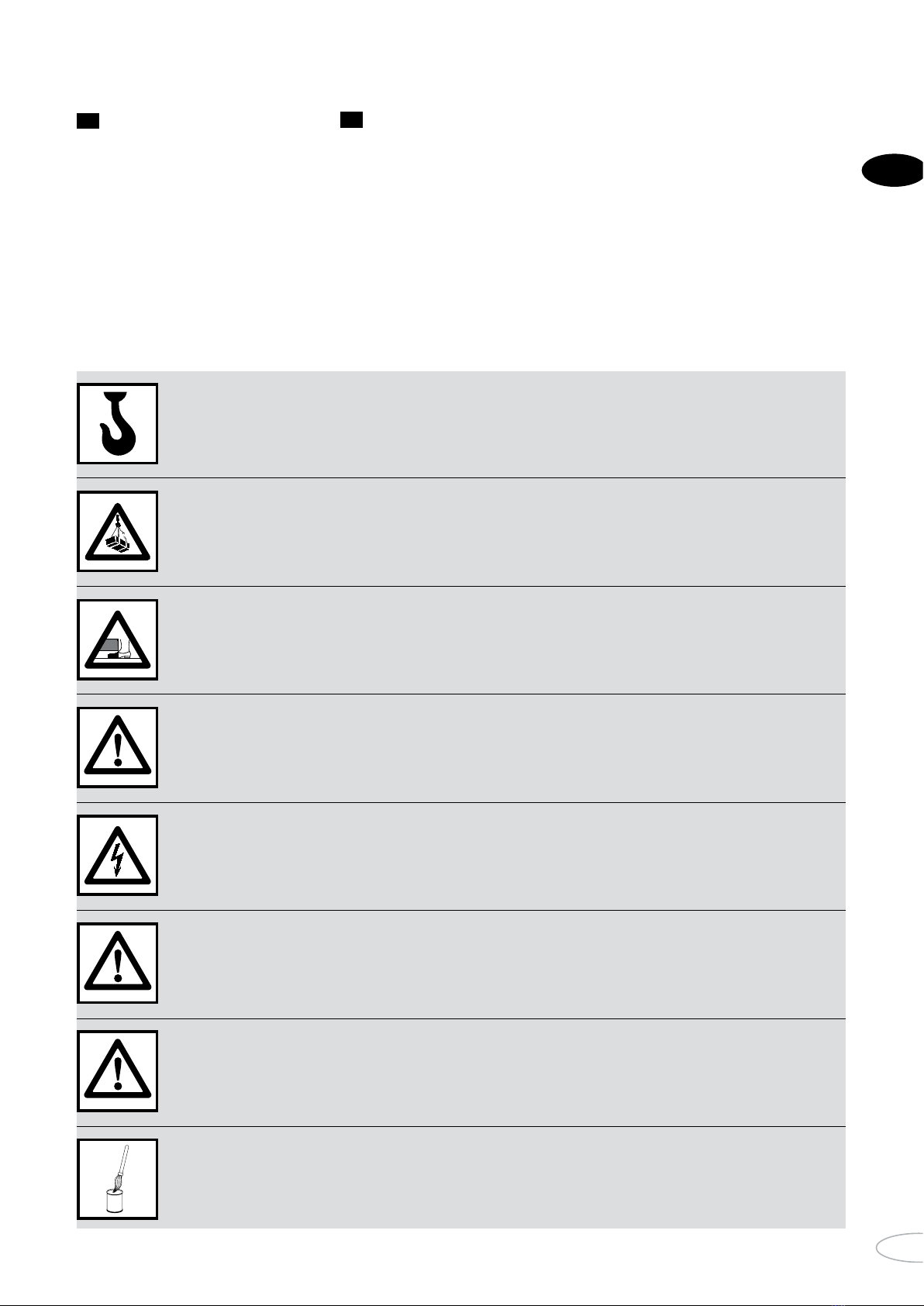
• When performing all installation
tasks, switch off the power supply and
secure the system to prevent it from
being switched on by an authorised
person.
• During installation, parts can drop,
which may result in injury to people
and damage to goods.
• Contact with electrically live compo-
nents may result in electric shock.
Make sure that the customer's elec-
trical system has been installed in
accordance with valid safety requi-
rements.
• Never connect a mains voltage supply
to the control unit; this will result in
irreparable damage to the electronics.
• Only perform welding and grinding
tasks on the leveller if expressly
permitted in the position in question.
Ensure adequate ventilation in order
to prevent build-up of an explosive
atmosphere of dust and other com-
bustible materials.
Warning
++ WARNING +++ WARNING +++ WARNING ++
X1
X2
X1 = X2
(± 10 mm)
• The area of application of this leveller
is described in the EN 1398 standard.
• Installation, repairs, maintenance
and dismantling must be carried out
by qualified professionals.
• During commissioning, the qualified
technician doing the work must be
alert to possible hazards and check
that the leveller operates correctly.
Read this first!
++ WARNING +++ WARNING +++ WARNING ++