novotechnik 4800-R User manual

1 General description
This device is a magnetic transducer for direct, precise and
absolute measurement of a rotary position in control,
regulation and measuring applications using touchless
magnetic sensing technology.
2 Safety instructions
2.1 Conventional application
The RFC transducer is intended to be installed in a machine orsystem.
Together with a controller it comprises a rotary position measuring system and
may only be used for this purpose.
In case of unauthorized modications, non-permitted usage or non-observance of installation
instructions, the warranty and liability claims will be lost.
2.2 Installation and startup
The transducer must be installed only by qualified personnel in consideration of all
relevant safety regulations.
Non-observance of the installation instructions will void any warranty or liability claims.
All necessary safety measures to protect personnel and property in case of a transducer
defect or failure must be taken before startup.
Strong magnetic or electromagnetic fields in close proximity of the transducer
may lead to faulty readings!
2.3 Check connections
Improper connections and overvoltage can damage the transducer.
Please always check the connections carefully before turning on the system.
2.4 Turning on the system
Please note that the system may execute uncontrolled
movements when rst turned on or when the transducer is part
of a closed-loop system whose parameters have not yet been set.
Therefore make sure that no hazards can result from these situations.
2.5 Check output values
After replacing or repairing a transducer, it is advisable to verify its ouput
values for start and end position of its position marker in manual mode.
2.6 Check functionality
The functionality of the transducer system and all its associated
components should be regularly checked and recorded.
2.7 Failure malfunction
If the transducer system doesn ‘t operate properly, it should be taken
out of service and protected against unauthorized use.
1 概要
このデバイスは、タッチレス磁気センシング技術を使用して、制御、調整、
および測定アプリケーションで回転位置を直接、正確、絶対的に測定するため
のホール効果の非接触センサーです。
2 安全上の注意
2.1 使用目的
ロータリーセンサは、機械またはシステムに設置することを目的としています。
コントローラーと一緒に回転位置測定システムを構成し、この目的にのみ使用
できます。
改造、不適切な使用、またはインストール手順の不遵守は、保証の
喪失につながり、責任請求を無効にし、危険な状態を引き起こす可能性があり
ます。
2.2 インストールと起動
ロータリーセンサは、関連するすべての安全規制を考慮して、資格のある担当
者のみが設置する必要があります。
インストール手順に従わない場合、保証または責任の請求は無効になります。
ロータリーセンサの欠陥または故障の場合に人員と財産を保護するために必要
なすべての安全対策は、起動前に実行する必要があります。
ロータリーセンサのすぐ近くに強い磁場または電磁場があると、
信号障害や危険な状態につながる可能性があります。
2.3 接続を確認する
不適切な接続と過電圧は、ロータリーセンサを損傷する可能性があります。
システムの電源を入れる前に、必ず接続を注意深く確認してください。
2.4 システムの電源を入れる
システムは、特にロータリーセンサのパラメータがまだ設定されていない制御
システムの一部である場合、最初の電源投入時に制御されていない動作を実行
する場合があります。 したがって、これが人員や財産に危険が及ばないよう
にしてください。
2.5 出力値を確認する
ロータリーセンサの交換後は、手動モードで開始位置と終了位置の出力値を確
認することをお勧めします。
2.6 機能の確認
ロータリーセンサシステムとそれに関連するすべてのコンポーネントの機能を
定期的にチェックしてください。
2.7 故障の誤動作
ロータリーセンサシステムが適切に動作しない場合は、使用を停止し、不正使
用から保護してください。
Page 1
RFC-4800 の使用説明書 / RFC 4800 Instructions for Use
シリーズ / モデル 600(RFC 48xx 6xx 17x xxx)mit PNP Schaltfunktion / PNP スイッチング機能付き

Page 2
3 インストール /Installation
ロータリーセンサ RFC48xx/Angle Sensor RFC 48xx
4 取り付け例 センサ - ポジションマーカー /Mounting examples sensor - position marker
ポジションマーカー Z-RFC-P01 / -P02 / -P07 / -P08
Position markers Z-RFC-P01 / -P02 / -P07 / -P08
動作範囲
ポジションマーカー
Z-RFC-PXX
中心径
アクティブ側
マーキング
φ6
-0.02
φ4
.1
例 A:標準取り付け 例 B:分離されたメディア
非磁性材料を使用してください!
可能な限りセンタリングするために
中心径を使用する
例C:プレートを介したマーカーの位置づけ
注意:ポジションマーカーの動作範囲は仕様の範囲を超えないようにしてください。
(詳細はデータシートを参照してください)
それぞれのインストール手順と動作範囲については、
別紙のポジションマーカーインストール手順を遵守してください。
RFC-4800 の使用説明書 / RFC 4800 Instructions for Use
シリーズ / モデル 600(RFC 48xx 6xx 17x xxx)mit PNP Schaltfunktion / PNP スイッチング機能付き
ラベル
ポジションマーカーのマーキング位置がケーブル方向にある場合
線形出力信号は 50%(12mA)です。
When the marking of the position marker is pointing to cable
outlet, the linear output signal is at 50% (12mA)

RFC-4800 の使用説明書 / RFC 4800 Instructions for Use
シリーズ / モデル 600(RFC 48xx 6xx 17x xxx)mit PNP Schaltfunktion / PNP スイッチング機能付き
5 電気的接続 / Electrical Connections
供給電圧 / Supply Voltage: 24VDC(18...30VDC)
消費電流 / current draw: typ.25mA(無負荷)
ケーブル / cable:
8x0,25 mm² リード線シールド付き /
Shielded cable with lead wires 8x0,25 mm2
ケーブルタイプ:C-V1-11Y / 8LiY 0.25mm² / cable type: C-V1-11Y / 8LiY 0,25mm2
配線 / wire assignment:
出力 / outputs:
1 x 電流出力 4..20mA、負担≤ 500 Ω
1 x Stromausgang / current output 4..20mA/Burden ≤ 500 Ω
2 xPNP スイッチ出力 / PNP スイッチ出力最大負荷 / 負荷 30mA
パーマネント / 定常
2 x PNP Schaltausgang / PNP switch output/Max. Last / load 30mA dauerhaft / steady
信号 Signal ケーブル色 Wire colour
供給
Supply 緑Green
グランド
Ground 茶 Brown
信号出力
4..20mA Signal Output 4..20mA 白 White
PNP スイッチ出力 1
PNP Switch output 1 赤Red
PNP スイッチ出力 2
PNP Switch output 2 桃Pink
ティーチインライン 1
Teach-In Line 1 黄 Yellow
ティーチインライン 2
Teach-In Line 2 灰 Grey
ティーチインライン 3
Teach-In Line 3 青 Blue
シールド
shield - -
CAUTION ! Extension of shielded cable demands a sucient shielding !
CAUTION ! Converted cable may show dierent colour coding !
注意! シールドケーブルを延長する場合、十分なシールド減衰があること
を確認してください!
注意! 組み立てられたケーブルは色の割り当てが異なります!
6 出力信号 / Output Signals 測定範囲
アナログ
出力
測定範囲の開始
中心位置
測定範囲の修了
ON1 OFF1
ON2 OFF2
1/2 の切り替え出力は、測定範囲内で自由にプログラム可能です。
Page 3

RFC-4800 の使用説明書 / RFC 4800 Instructions for Use
シリーズ / モデル 600(RFC 48xx 6xx 17x xxx)mit PNP Schaltfunktion / PNP スイッチング機能付き
7 PNP スイッチ出力のスイッチポイントのティーチイン
Teach-In of the switching edges of the PNP switch outputs
7.1 PNP スイッチのティーチングに関する一般事項
ティーチインは 3 つのプログラミングラインを介して行われます。
ディスプレイユニットを使用して、プログラミング中の電圧状態を監視します。
関連するスイッチ出力と、センサとの間の距離が大きいプログラミング、
ディスプレイユニット間はブリッジ可能です。(最大 10m)
ティーチインは、プログラミングラインに電圧を印可して行います。
プログラミング後、プログラミングラインは非接続(内部プルアップ)、
または GND に接続してください。
ティーチイン中に電流の出力を接続表示し、例えば電圧計を介して電流測定を
することが効果的と考えられます。
実際の機械的ポジションを簡単に制御することが可能です。
7.1 generals about Teaching the PNP switches
The Teach-In uses 3 extral electrical lines, the programming
lines.
The user feedback during programming is provided by the
voltages of the switch outputs.
Even large distances can be bridged between sensor and
programming/monitoring unit (up to10m).
The Teach-In works by applying the supply voltages to the
programming lines. After programming is nished the
programming lines can be left unconnected (internal pull up) or
are connected to Ground.
It is recommended to connect and display the current output
during the teach-In procedure, for example using a DVM with
current measurement. So the actual mechanical position easily
can be controlled.
7.2 備考
• ティーチインは Novotechnik の Teach-InBox(Z-RFC-T01)を使用し
簡単に行えます。
LED のスイッチ出力とプログラミング入力が LED による操作で行えます。
Teach-InBox(Z-RFC-T01)は別売品としてご用意しております。
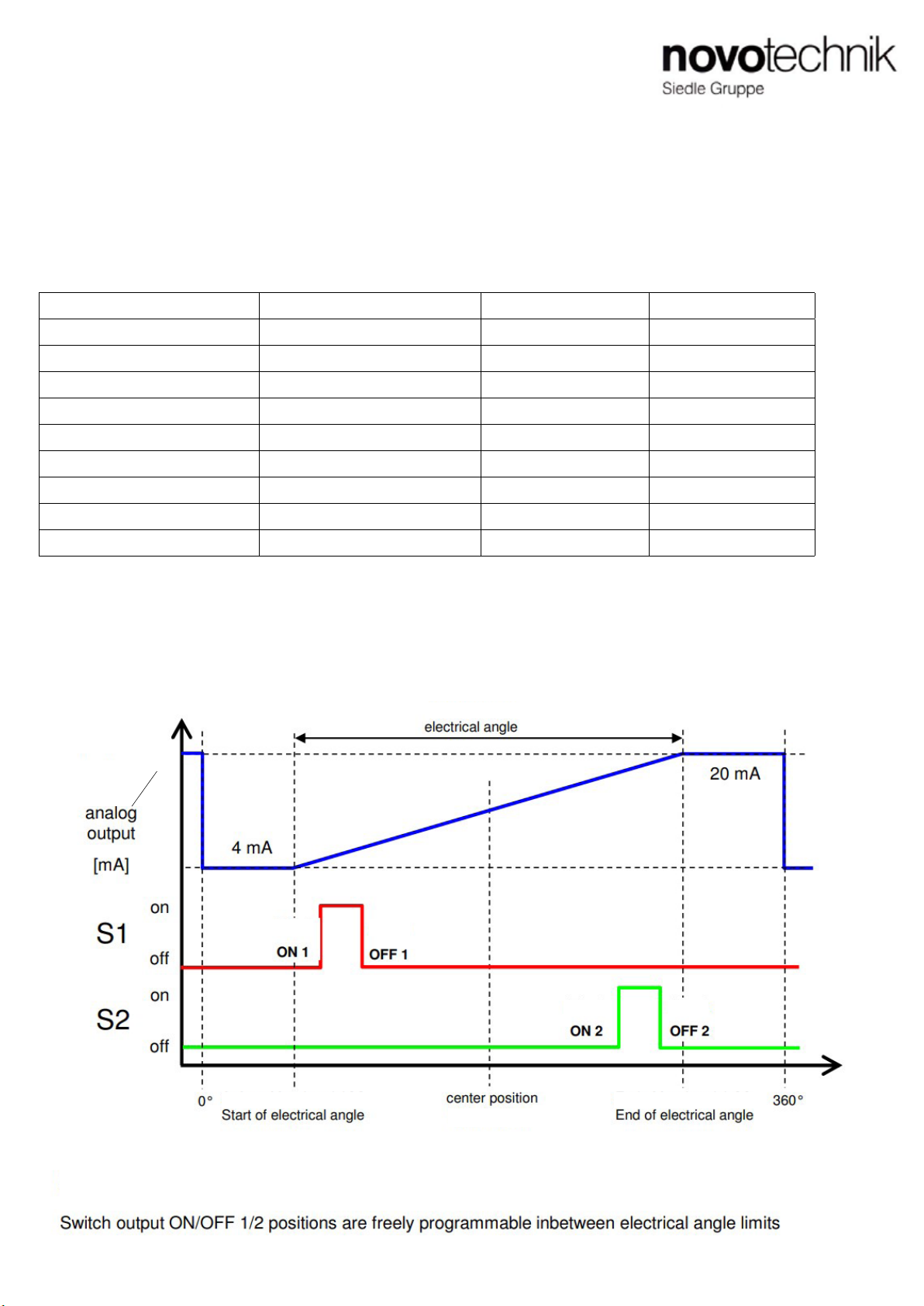
•OFF エッジは常に大きな電流出力である必要があります。
現在の出力値は、対応する ON エッジとして存在します。
• 各チャンネルの ON/OFF スイッチエッジを任意で選択できます。
• スイッチ出力は、必要に応じて何度でも繰り返しプログラムできます。
• スイッチ出力のデフォルト設定はされていません。
つまりスイッチが OFF のポジションにあります。
7.2 Remarks
• The Teach-In is done very comfortable when the Teach-In Box
from Novotechnik (Z-RFC-T01) is used. The switch outputs are
led to LED ‘s and the programing inputs are operated by
buttons thus making the teach-in process much easier.
It is available as an add-on product.
• The OFF edge has always to be at a larger current output
value than the corresponding ON edge.
• The on/o switching edges for each channel can be chosen
freely and independently across the specied electrical range.
• The switch teach-In can be repeated very many times.
• Default setting for the switch outputs is unprogrammed. This
means the switches are OFF.
7.3 PNP スイッチ 1 のティーチインプロセス(チャンネル 2)
電線を直接使用
ティーチプロセスステップ ユーザーアクション センサリアクション
1. プログラミングモード
PNP チャンネル 1
(チャンネル 2)を呼び出す
ライン Pr1 と Pr2(Pr3)を
同時に 3 秒間 Ub へ接続
スイッチ出力 1
(出力 2 の切り替え)が約 2 秒間点灯
します
Pr1 および Pr2(Pr3)2 秒以内に Ub
から離します
スイッチ出力 1
(スイッチ出力 2 の切りかえ)
ON/OFF をすばやく切りかえします
->
センサはプログラミングモードです
2.ON スイッチポイント
プログラム
ポジションマーカーを任意の
ON ポジションへ
(電流出力が実際のポジションを
示します)
ライン Pr2 を Ub に接続します スイッチ出力 1
(スイッチ出力 2)スイッチ
ON/OFF が遅い
-> ON スイッチポイントが
プログラムされています
3.OFF スイッチポイント
プログラム
ポジションマーカーを任意の
機械的 OFF ポジションへ
(電流出力は実際のポジションを示し
ます(例:5mA))
ライン Pr3 を Ub に接続します スイッチ出力 1
(出力 2 の切り替え)
静的
->OFF 切りかえポイントは
プログラミングされました
4. チャンネル 1 と 2 の
スイッチポイント
プログラム済み
終了しました!
Teach Process step User action Sensor reaction
1. Enter programming
mode for PNP channel 1
(channel 2)
put Line Pr1 and Pr2 (Pr3) to
Ub at the same time for 3s
switch output 1 (switch
output 2) activates for ca.
2s
release line Pr1 and Pr2
(Pr3) from Ub inbetween 2s
switch output 1 (switch
output 2) toggles fast ->
Sensor is in Programming
mode
2. Teach ON sw itching
point
drive position marker
mechanically to the desired
ON position
(Current output displays
actual position)
put line Pr2 shortly to Ub switch output 1 (switch
output 2) toggles slow er
-> ON sw itching point is
teached
3. Teach OFF switching
point
drive position marker
mechanically to the desired
OFF position
(Current output displays
actual position)
put line Pr3 shortly to Ub switch output 1 (switch
output 2) becomes static
-> OFF sw itching point is
teached
4. The switching points
for channel 1 and 2 are
conpletely teached
nished
Page 4
7.3 Teach-In Process for PNP Switch No. 1 (No. 2 in
Brackets) directly using the electrical lines

Page 5
7.4 PNP スイッチチャンネル 1 のティーチインプロセス
(チャンネル 2)Novotechnik の Teach-In Box(Z-RFCT01)を使用
7.4
Teach-In Process for PNP Switch channel No. 1
(channel No. 2 in brackets) using the Teach-In Box (Z-RFCT01) from Novotechnik
■各種お問合せ
㈱ビー・アンド・プラス
〒 355-0311
埼玉県比企郡小川町高谷 2452-5
E-mail:
T621108Aj 2021.02.18
㈱ビー・アンド・プラスは novotechnik 社の正規日本代理店です。
RFC-4800 の使用説明書 / RFC 4800 Instructions for Use
シリーズ / モデル 600(RFC 48xx 6xx 17x xxx)mit PNP Schaltfunktion / PNP スイッチング機能付き
Teach Process step User action Sensor reaction
1. Enter programming
mode for PNP channel 1
(channel 2)
press Button T1 and T2 (T3)
at the same time for 3s
LED1 (LED2) glow s for ca.
2s
release Button T1 and T2
(T3) inbetw een 2s
LED1 (LED2) blinks fast ->
Sensor is in Programming
mode
2. Teach ON switching
point
drive position marker
mechanically to the desired
ON position
(Current outpress displays
actual position)
press Button T2 shortly LED1 (LED2) blinks slow er
-> ON sw itching point is
teached
3. Teach OFF switching
point
drive position marker
mechanically to the desired
OFF position
(Current outpress displays
actual position)
press Button T3 shortly LED1 (LED2) blinks slow er
-> OFF sw itching point is
teached
4. The switching points
for channel 1 and 2 are
conpletely teached
nished !
ティーチプロセスステップ ユーザーアクション センサリアクション
1. プログラミングモード
PNP チャンネル 1
(チャンネル 2)を呼び出す
ボタン T1 および T2(T3)を同時に
3 秒間押します
LED1(LED2)が約 2 秒間点灯します
2 秒以内にボタン T1 および T2(T3)
を離します
LED1(LED2)の点滅が速くなります
-> センサが入っています
プログラミングモード
2.ON スイッチポイント
プログラム
ポジションマーカーを任意の
ON ポジションへ
(電流出力が実際のポジションを示します)
ボタン T2 を短く押します LED1(LED2)が点滅が遅くなります
-> ON スイッチポイントは
プログラムされました
3.OFF スイッチポイント
プログラム
ポジションマーカーを任意の
機械的 OFF ポジションへ
(電流出力が実際のポジションを示します)
ボタン T3 を短く押します LED1(LED2)が点滅が遅くなります
-> ON スイッチポイントは
プログラムされました
4. チャンネル 1 と 2 の
スイッチポイント
完了、プログラム済み
終了しました!
7.5 リセット機能
T1 ボタンを 7 秒以上押して 2 秒以内に離すと ,(両方の LED が点灯するとすぐに)
EEPROM にプログラムされたすべてのスイッチポイントが削除されます。
その後、配信ステータスに対応するスイッチングポイントは保有されません。
削除は、次の 2 つのスイッチ出力が約 5 秒間「点滅」によってアクティブになります。
7.5 Reset Function
By pressing Button T1 for more than 7s and release of T1 after
2s (as soon as both LED ‘s are on) the user programmed Teach
Positions are deleted in EEPROM.
No more switching points are stored then, this corresponds to
the condition of delivery.
The deletion is displayed by toggling switch outputs for ca. 5s.
8 Installation Notes
Pay attention to the maximum tightening torque of 250 Ncm when
fastening the delivered button head socket screws with ange.
Using a dierent screw type (M4) a washer is to be used, the
max. tightening torque is 200 Ncm then.
If existing, connect the cable shield to GND.
Minimum bending radius of the cable is 60mm. Avoid steady
tension on the cable in any direction.
If in the application the cable is moving, appropriate action is to be
taken to x it after the outlet of the sensor with such as xation
clamps, protection tubes etc...
8 取り付け例
配送時同梱のなべ頭ネジを使用し、センサハウジングの取り付けをしてください。
取り付け時の最大トルクは 250Ncm です。
他のネジ(M4)を使用する場合のワッシャーを使用してください。
最大締め付けトルクは 200Ncm です。
存在する場合は、ケーブルシールドを GND に接続する必要があります。
ケーブルの最小曲げ半径は 60mm です。
ケーブルのどの方向にも引っ張らないようにしてください。
使用中にケーブルを移動する場合は、出口部のひずみを緩和するために、ケーブルを
クランプなどで固定する必要があります。
Other novotechnik Media Converter manuals
Popular Media Converter manuals by other brands

Moxa Technologies
Moxa Technologies TCF-142 Series Quick installation guide

StarTech.com
StarTech.com HDMI2HDMI instruction manual

HEIDENHAIN
HEIDENHAIN LIF 171R Mounting instructions

Yamaha
Yamaha YMC10 owner's manual

Digitus
Digitus DN-82010-1 user manual

Aus Electronics Direct
Aus Electronics Direct HDCN0053M1 user manual

American Dynamics
American Dynamics RCSN422 installation guide

J-Tech Digital
J-Tech Digital JTD-164 user manual

Microchip Technology
Microchip Technology MCP1630 NiMH user guide

Huawei
Huawei DEC6108 quick start

Baumer
Baumer HOG 75 K Installation and operating instructions

Z3 Technology
Z3 Technology Sitara Z3-AM572x-RPS User instructions