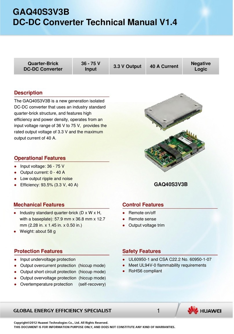
Huawei DEC6108 User manual

DEC6108
HD Decoder
Quick Start
Issue: 02
Copyright © Huawei Technologies Co., Ltd. 2017. All rights reserved.
BOM: 31508285
Default login URL:
URL:
URL accesso predefinito:
https://192.168.2.101:8443/
user name/password:
nom d'utilisateur/mot de passe de connexion par défaut du:
nome utente/password:
admin/Change_Me

1.Safety Precautions
1.1 Requirements
Keep the device dry and prevent any violent collision when transporting, storing, and installing
the device.
Do not disassemble the device. Contact the maintenance station if faults occur on the device.
Avoid any unauthorized modifications on the design of the structure, security, or performance.
Installation and maintenance must be performed by professional technical engineers.
1.2 Usage Precautions
Before installing the device, ensure that components are proper operations have been made.
Ensure that the operating temperature ranges from 0°C to 45°C and the relative humidity ranges
from 5% to 95%.
Install the device in a well-ventilated area. During installation, keep the device dry and prevent any
violent collision.
Power off the device before installation .
If an exception (such as smoking and abnormal sound or smell) occurs, stop using and power off
the device immediately. Then remove all cables (including power cables and network cables).
Prevent water or any other liquids from infiltrating the device. If any liquid infiltrates the device
accidentally, power off the device immediately and disconnect remove all cables (including power
cables and network cables).
Never install or use the device in a place in which explosive or flammable goods are used or stored.
Before cleaning the device, stop using and power off the device.
Qualification Card
1

2
2.DEC6108 At-a-Glance
The DEC6108 is a multifunctional HD video decoder that is designed for video surveillance
solutions. It can display decoded streams on the video wall. As a lightweight and reliable decoder, it
supports H.264 and H.265 video encoding formats and multiple network transmission protocols.
Functional
Specifications
Description
Decoding
performance
Support H.264 and H.265 video encoding formats.
The number of live video viewing channels depends on the
resolution in case of H.264 and H.265 decoding as follows:
D1(25fps) or lower : 256 720P(30fps) : 128
1080P(30fps) : 64 4K(30fps):16
Support simultaneous decoding under different resolutions. The
total bandwidth cannot exceed 480 Mbit/s.
Video display
control
Support HDMI video output (eight HDMI ports in total).
The HDMI output supports following resolutions:
4K(30fps) : 3840*2160 (only supported by odd-numbered ports )
1080P:1920*1080
UXGA:1600*1200(only supported by odd-numbered ports)
SXGA:1280*1024
720P :1280*720
XGA :1024*768
Each group of HDMI1+HDMI2, HDMI3+HDMI4, HDMI5+HDMI6, or
HDMI7+HDMI8 shares one decoding chip. Each group of ports
shares the output specification of the decoder. For example, each
group of ports supports a maximum of 4 4K, 16 1080p, 32 720p, or
64 D1 live video channels.
WARNING:
Replacing a battery incorrectly might result in an explosion. Replace a battery only with the same or
equivalent type recommended by the manufacturer. Dispose of used batteries according to the
manufacturer's instructions.
As VDR bridged primary and earth. This built-in type power supply only can be used in permanently
connected equipment, pluggable type B equipment or pluggable type A equipment provided with a
permanently protective earthing terminal.
This equipment is compliant with Class A of CISPR 32. In a residential environment this equipment
may cause radio interference.
CAUTION:
Disconnect the power cord before serving to avoid electric shock.
Any changes or modifications not expressly approved by the party responsible for compliance
could void the user’s authority to operate this equipment.
Double pole/neutral fusing.
NOTE:
This equipment has been tested and found to comply with the limits for a Class A digital device,
pursuant to Part 15 of the FCC Rules. These limits are designed to provide reasonable protection
against harmful interference when the equipment is operated in a commercial environment. This
equipment generates, uses, and can radiate radio frequency energy and, if not installed and used
in accordance with the instruction manual, may cause harmful interference to radio communications.
Operation of this equipment in a residential area is likely to cause harmful interference in which case
the user will be required to correct the interference at his own expense.
ATTENTION:
Danger d'explosion si la pile n'est pas remplacée correctement. Ne la remplacer que par une pile
de type semblable ou équivalent, recommandée par le fabricant. Jeter les piles usagées
conformément aux instructions du fabricant.
Débranchez le cordon d'alimentation avant de servir afin d'éviter tout risque d'électrocution.
Double pole/fusible sur le neutre.
3.Front and Rear View of the Device
3
Front view
Rear view
5.
Device Installation
5.1 Desktop Installation
Stick and fix four bottom caps at the bottom of the device, as shown in the following figure. Then
place the device horizontally on a desktop.
4.Packing List
AC power cable 1PCS
Mounting ear 2PCS
Bottom cap 4PCS
M4*6 screw 6PCS
OT terminal
Quick Start
2PCS
1PCS
No.
1
2
3
4
5
6
Accessory Quantity
Power health indicator
Link indicator of the GE port
Power cable retention clip 1PCS 7
Ground
terminal
COM port
GE port
HDMI1
Power button
Power port
HDMI2
HDMI3
HDMI4
HDMI5
HDMI6
HDMI7
HDMI8

4
3
Install mounting ears. Take six M4*6 screws. Use three screws to configure one mounting
ear on the left of the front panel and the same way to configure the other ones on the right side.
Then use a Phillips screwdriver to fasten the screws to fix the mounting ears, as shown in the
lower-left figure.
5.2 Cabinet Installation
Properly plan the installation location of floating nuts in the cabinet. A decoder needs four floating
nuts to fix the device, as shown in the lower-left figure.
1
2
As shown in step 1 in the lower-right figure, insert one leg of the floating nut into the square hole
from inside of the cabinet, so that the leg hooks over the lower frame of the square hole. As
shown in step 2 in the lower-right figure, use the floating nut hook to catch the other leg of the
floating nut. Pull the hook forward until the leg hooks over the upper frame of the square hole.
4
Install the device. Carry the device to be cabinet. Ensure that the mounting ears at both sides of
the device are tightly attached to the mounting bar in front of the cabinet. Use one hand to hold
the device. Use the other hand to thread M6 screws (prepared by customers) through the slotted
hole on the mounting ear. Use a Phillips screwdriver to fix the M6 screws on the mounting ears.
Each mounting ear uses two M6 screws, as shown in the lower-right figure.
Note:
The decoder is compact and lightweight. It can be directly fixed on the cabinet with M6 screws and
mounting ears without using a guide rail. If a guide rail has been installed in the cabinet, you are
advised to remove the guide rail first and then install the device in the cabinet. The decoder is
equipped with right-to-left airflow, so installing a guide rail may affect the heat dissipation and lower
the device performance accordingly.
When the decoder is installed in a cabinet, do not install the rubber foot which will occupy the cabinet
space.
5.2.1 Single-Device Deployment Scenario

5
5.3 Wall-Mount Device Installation
1
Take six M4*6 screws. Use three screws to configure one mounting ear on the left of the front
panel and the same way to configure the other ones on the right side. Use a Phillips screwdriver to
fasten the screws used to fix the mounting ears, as shown in the lower-left figure.
2
Mark the installation position. Mark the four installation holes on the wall. The vertical distance
among holes is 32 mm and horizontal distance is 465 mm. Then use a plumb line to check whether
the holes are horizontal, as shown in the lower-right figure.
5.2.2 Multi-Device Deployment Scenario
Note:
For details about how to install a device in the cabinet, see the single-device deployment scenario.
This section introduces how to install multiple devices in the cabinet
When multiple decoders need to be installed, the decoders can be stacked, and no space needs to be
reserved between each two decoders, as shown in the following figure.

3
4
Drill holes and install M6 expansion bolts. Use a hammer drill to drill holes in marked positions and
install expansion bolts (prepared by users) after cleaning, as shown in the lower-left figure.
.
Install the device on the wall. Connect the M6 expansion bolts (attached with the screws) through
the holes on the mounting ears on both sides of the device. Then use a screwdriver to fasten the
screws into the expansion bolts to fix the device on the wall (front panel upward), as shown in the
lower-right figure.
Use a Phillips screwdriver to connect one end of the PGND cable to the ground terminal of the
device, and connect the other end to the ground point of the cabinet or work station. The PGND
cable is prepared by the customer, and its diameter must range from 16 AWG to 18 AWG.
Use a network cable to connect the GE port of the device to a switch.
(Optional) If the decoder fails and needs to be debugged and maintained, use a network cable
to connect the COM port of the device to the PC.
Connect the HDMI video output port to the video wall. There are a total of eight HDMI ports.
Choose ports based on the site requirements.
Insert one end of the power cable to the power supply interface of the device and the other end
to the power outlet.
Turn on the power switch. Skip this step if DEC6108 is used.
1
2
3
4
5
6
6.Connecting Cables
Video wallSwitch
PC Client
5
4
3
1
GE1
2
GE1
6
6

Warranty Card
Thank you for choosing products of Huawei Technologies Co., Ltd. (Huawei). To be entitled for warranty service for
the product, please read the following warranty statements carefully.
1. Warranty Period
Unless otherwise stated specifically by Huawei, the following periods apply:
Duration of Hardware Warranty: 12 months
Duration of Software Media: 3 months
The start date of the warranty:
(1) If you have not purchased the engineering or installation service, the warranty starts on the 90th day after the date
of the product shipment from Huawei.
(2) If you have purchased the engineering or installation service, the warranty starts from the date the preliminary
acceptance certificate is signed, but no later than 90 days after Huawei ships the product. If the preliminary acceptance
certificate is signed 90 days after shipment, the warranty automatically starts on the 90th day after shipment.
Notes:
1. When you purchase a product from Huawei, please confirm the date when the product will be shipped from Huawei,
and check other warranty-related information.
2. For expansion and replacement parts, you are entitled to either of the following warranties (whichever is longer):
(1) A 90-day warranty starting from the date the replacement parts are shipped
(2) The remaining warranty of the original equipmen
2. Service Guidelines
This warranty card entitles you to free warranty service within the warranty period. For a complete listing of
applicable warranties, please visit http://e.huawei.com/, choose Support > Maintenance & Warranty > Warranty,
and view the Enterprise Product Limited Warranties on the web page.
Technical Support: For post-sale technical support, Account or maintenance questions, contact:
TAC Support: Visit http://support.huawei.com/enterprise and choose Contact > Global Service Hotline to find the
service hotline available in your country.
Complete the form below and keep for ready reference:
Product supplier:
Supplier telephone number:
Product serial number:
Table of contents
Other Huawei Media Converter manuals

Huawei
Huawei SUN2000 Series User manual

Huawei
Huawei GAQ37S12B-4 User manual

Huawei
Huawei MERC Smart PV Optimizer User manual

Huawei
Huawei IRD6000 User manual

Huawei
Huawei R4815N1 User manual

Huawei
Huawei NAD12S10-A User manual

Huawei
Huawei GDQ54S12B-4A User manual

Huawei
Huawei GAQ40S3V3B User manual

Huawei
Huawei ADF10S48B User manual