NOVOTEST UD3701 User manual

Operation Manual
Ultrasonic Flaw Detector
NOVOTEST UD3701
Address:
51200, Ukraine, Novomoskovsk, str. Spasskaya,5
Sales:
cell.: +38-067-593-59-77
http://novotest.biz/
Warranty maintenance and service support:
cell.: +38-067-593-59-77

Operation manual
Ultrasonic Flaw Detector NOVOTEST UD3701
Page 2
CONTENT
GENERAL INFORMATION...................................................................................................................5
ABBREVIATION USED .........................................................................................................................6
1 DESCRIPTION AND OPERATION OF THE DEVICE AND ITS COMPONENTS.........................7
1.1 The purpose of the device...............................................................................................................7
1.2 Technical characteristics of the device ...........................................................................................7
1.3 Standard delivery set.......................................................................................................................9
1.4 Parts.................................................................................................................................................9
1.5 Probes............................................................................................................................................11
1.5.1 Probe types.............................................................................................................................11
1.6 Design and functioning.................................................................................................................12
1.6.1 Design of the flaw detector....................................................................................................13
1.7 Device modes................................................................................................................................14
1.7.1 «FLAW DETECTOR» mode.................................................................................................14
1.7.2 «SETTINGS» mode...............................................................................................................23
1.7.3 «ARCHIVE» mode ................................................................................................................24
1.7.4 «RESULTS» mode ................................................................................................................24
1.7.5 «INFORMATION» mode......................................................................................................25
1.8 Means of measurement, tools and accessories..............................................................................25
1.9 Marking and sealing......................................................................................................................25
1.10 Packing........................................................................................................................................25
2 UNTENDED USE ...............................................................................................................................26
2.1 Maintenance limitations................................................................................................................26
2.2 Preparing the device for use..........................................................................................................26
2.2.1 Visual inspection....................................................................................................................26
2.2.2 Charging the battery...............................................................................................................26
2.2.3 Selection the probe.................................................................................................................26
2.2.4 Connecting the probe.............................................................................................................27
2.3 Preparing the object of testing ......................................................................................................29
2.4 Using the device............................................................................................................................29
2.4.1 Turning on..............................................................................................................................29
2.4.2 Device navigation ..................................................................................................................30
2.4.3 Settings...................................................................................................................................32
2.4.4 Setting the probe parameters..................................................................................................34
2.4.5 Setting the signal view...........................................................................................................36
2.4.6 Setting the device for testing..................................................................................................38
2.4.7 Automatic signalization of defects.........................................................................................42
2.4.8 «TVG» mode..........................................................................................................................43
2.4.9 «DAC» mode .........................................................................................................................46
2.4.10 «DGS» mode........................................................................................................................50
2.4.11 Additional modes.................................................................................................................51
2.4.12 Operating with device memory............................................................................................52
2.5 Calibration of flaw detector ..........................................................................................................55
2.5.1 Determination of delay in the prism of straight beam probe .................................................55
2.5.2 Determination of delay in the prism of angle beam probe.....................................................55

Operation manual
Ultrasonic Flaw Detector NOVOTEST UD3701
Page 3
2.5.3 Determination of entry angle of the probe.............................................................................56
2.5.4 Determination of probe arrow................................................................................................56
2.5.5 Determination of UT waves velocity in the tested object by straight beam probe................57
2.6 Connecting the device to PC.........................................................................................................58
2.6.1 Software installation AWP_UD3701.....................................................................................58
2.6.2 Software operation AWP_UD3701 59
3 TECHNICAL MAINTENANCE OF THE PRODUCT AND ITS COMPONENTS .........................64
3.1 Safety measures.............................................................................................................................64
3.2 Verification ...................................................................................................................................64
3.2.1 Verification and verifying instruments..................................................................................64
3.2.2 Requirements for verification officer qualification, requirements for safety and
verification conditions.....................................................................................................................65
3.2.3 Visual inspection....................................................................................................................66
3.2.4 Functionality test..................................................................................................................666
3.2.5 Determination of the modal accuracy when measuring echo-signal amplitudes from
defects .............................................................................................................................................66
3.2.6 Checking the nonlinearity of vertical scanning......................................................................67
3.2.7 Determination of reference values of conventional response, range of the control gate
and signal/noise ratio ......................................................................................................................68
3.2.8 Determination of the basic accuracy when measuring distance to the defect (thickness)
by straight beam probes ..................................................................................................................69
3.2.9 Data-report of verification .....................................................................................................70
3.3 Warranty........................................................................................................................................70
3.3.1 Basic Warranty.......................................................................................................................70
3.3.2 Extended warranty .................................................................................................................70
3.3.3 Warranty for repaired or replaced parts.................................................................................70
3.3.4 Wear parts ..............................................................................................................................70
3.3.5 Duties of the owner................................................................................................................71
3.3.6 Warranty Limitations.............................................................................................................71
3.3.7 Other cases not covered by the warranty...............................................................................72
3.3.8 Guarantees and consumer legislation.....................................................................................72
3.4 Maintenance of the device ............................................................................................................72
4 MAINTENANCE ................................................................................................................................74
5 STORAGE...........................................................................................................................................74
6 TRANSPORTATION..........................................................................................................................74
7 RESYCLING.......................................................................................................................................74
APPENDIX A.........................................................................................................................................75

Operation manual
Ultrasonic Flaw Detector NOVOTEST UD3701
Page 4
Caution!
Please read this manual carefully before using the device –Ultrasonic Flaw Detector NOVOTEST
UD3701.
This operating manual (hereinafter OM) includes general information in order to give the
operating personnel understanding of functioning and operating rules of the Ultrasonic Flaw Detector
NOVOTEST UD3701 (hereinafter referred to as the device or flaw detector). The document contains
technical characteristics, description of the design and principle of operation, as well as information
necessary for the correct use of the device. Before starting work, it is necessary to read this manual, as
the device operation must be carried out by persons who are familiar with the operation principle and
the device design.
Correct and effective use of the device requires obligatory availability:
Testing methods;
Conditions for testing, according to testing methods;
Trained, and familiar with this OM user.
The enterprise-manufacturer reserves the right to make non-critical changes, without making
worse technical characteristics of the device. These changes may not be mentioned in the text of
current document.
The standard delivery kit of the device includes the operational documentation as a part of this
OM.
The present OM applies to all modifications of the device.

Operation manual
Ultrasonic Flaw Detector NOVOTEST UD3701
Page 5
GENERAL INFORMATION
Correct and effective use of flaw detector requires obligatory availability:
Technical characteristics of flaw detector comply with requirements of test tasks;
Relevant quality-control procedures;
Well-qualified operator.
Present OM gives operator only instructions about intended use of the device. It does not give
understanding about influencing factors while testing and basic principal of ultrasonic.
Ultrasonic
Operator must be familiar with basic principal of theory about propagation of ultrasonic waves,
including understanding of sound velocity, damping, echo and reflected signal, limitations and
boarders for sound beam, etc.
Study
Operator must complete relevant training courses for correct use of flaw detector, getting clear
understanding about general principal of ultrasonic testing and practical skills for testing the particular
kind of products.
Testing
For correct ultrasonic testing operator must have quality-control procedure for this particular
product and must know special requirements for ultrasonic testing: aims of testing, choice of
appropriative testing device (method of scanning), choice of the probe, determination of known testing
conditions in materials of such kind, choice of reflector with minimal surface, cutting-off level, etc.
Evaluation of defect area
There are two main methods of evaluation of defect area.
1. By defect boarders:
If the diameter of sound beam is less than defect area, then it can be used for determination of
defect boarders. The less is beam diameter, the more accuracy in determination of defect
boarders. And vice versa, when the beam is rather wide, then determined boarders could be
quit differ from real ones.
2. By amplitude of echo-signal:
If the beam radius is more than defect area, then defect area is evaluated by the next way:
maximal echo-signal amplitude of the defect is compared to maximal amplitude of artificial
reflector in a special test block. Usually, echo-signal amplitude of the real defect is less than
amplitude of artificial reflector with the same area. This is because of not the exact
perpendicular position of the real defect to the probe beam and irregular shape of defect
surface, and it should be taken into account when testing.
Quality-testing procedures
User must know and understand quality-testing procedures, which are worked out for relevant
products.
Thickness measurement
Thickness measurement by ultrasonic –is a result of mathematical multiplication of ultrasonic
velocity in material and impulse passing time. Flaw detector allows to get the precise time value for
ultrasonic waves. The correct velocity setting depends on operator.
Sound velocity
Accuracy for thickness measurement and for defect position evaluation basically depends on the
correct setting of ultrasonic velocity in the material. Velocity depends on material physical
characteristics and its temperature.

Operation manual
Ultrasonic Flaw Detector NOVOTEST UD3701
Page 6
ABBREVIATION USED
In this OM following abbreviations and symbols are used:
DGS –distance–gain-size (defect);
DAC –distance amplitude curve;
DTC –defect control (automatic signaling of defects);
TVG –time varied gain;
LCD –liquid crystal display;
NDT –nondestructive testing;
TO –tested object;
UT probe –ultrasonic probe;
DEP –dual element probe;
SS –standard sample;
RB - Reference block;
SO-2 -Calibration Block SO-2 (GOST 14782-86);
SO-3 -Calibration Block SO-3 (GOST 14782-86);
UT –ultrasonic;
US –ultrasonic waves;
DSP –digital signal processor;
DA converter –digital-to-analog converter;
AD converter –analog-to-digital converter;
TPP –thermal power plant;
NPP –nuclear power plant.

Operation manual
Ultrasonic Flaw Detector NOVOTEST UD3701
Page 7
1 DESCRIPTION AND OPERATION OF THE DEVICE AND ITS COMPONENTS
1.1 The purpose of the device
Flaw detector is designed for product testing as for the presence of defects, including:
discontinuity and homogeneity of materials, semi-finished and finished products, welds;
measuring depth and coordinates of defect;
thickness measurement of the product;
measuring UT waves velocity in the material.
Flaw detector implements shadow, echo and mirror-shadow testing methods. Flaw detector allows
user to create, record and store in nonvolatile memory temporary implementation of pulsed ultrasonic
signals and then further data loading to PC for analysis and documentation. Integrated liquid crystal
display (LCD) provides a mapping of ultrasonic signals in the form of A-scan, as well as images of
cross sections of testing objects in the form of B-scans. Ultrasonic Flaw Detector NOVOTEST
UD3701 has extensional functions of modern professional device:
color large 7-inch touch screen display of high resolution (800*480 pixels). Also, keyboard
is available;
lightweight, portable and ergonomic impact-resistant metal housing;
high-capacity battery.
Flaw detector can be used in mechanical engineering, aerospace, metallurgy, transportation, while
installation of steel constructions and equipment on TPP or NPP.
1.2 Technical characteristics of the device
Ultrasonic Flaw Detector NOVOTEST UD3701 is a portable device made in an impact-resistant
housing, inside which a board with electronic components and accumulators is placed. The main
characteristics of the device are presented in Table 1.1. Table 1.2 shows technical characteristics of the
device.
Table 1.1 –The main characteristics of the device
Dimensions, mm
250x150х50
Display, mm
155х85
(7-inch touch screen)
Weight, not more, kg
1,4
Battery, А/h
12
Charger voltage, V
5
Operating time without charging, h
up to 20
Operating temperature range, °С
from -30 to +55
Humidity, not more, %
95 when 35 °С
Allowable range for absolute accuracy of the device when measuring depth of defects (thickness):
not more ± (0,5 + 0,01·Hx) mm, where Hx –defect depth value (thickness) in mm.
Allowable range for absolute accuracy of the device when measuring coordinates of defects:
± (0,5 + 0,01·X) mm, where X –defect coordinate value in mm.
Allowable range for absolute accuracy of the device when measuring amplitudes ratio:
± 0,5 dB per every 10 dB.

Operation manual
Ultrasonic Flaw Detector NOVOTEST UD3701
Page 8
Table 1.2 –Technical characteristics of the device
Scan, µs:
–minimum
–maximum
0 –14
0 –1000
Delay, µs
0 –1000
Maximum thickness of tested object, mm
Up to 6000 (echo-signal) for steel
Velocity range, m/s
1000 - 9999
Delay in the prism, µs
0 –100
Damping, Оhm
50
Input impedance
50 Оhm / 600 Оhm
Amplitude of the probe pulse, V
200 (U1); 150 (U2); 100 (U3)
Repetition frequency of the probe pulse, Hz
Automatically controlled
from 10 to 100
Analog amplifier, MHz
wideband 0,4 –20
(-6 dB)
Gain control range, dB
126
The range of variation of temporal sensitivity adjustment
TVG, dB
Up to 70 (12 dB/µs)
Quantity of control points for TVG
16
Quantity of control points for DAC
16
Automatic signaling of defects (DTC –defect control)
dual-gates
Setting range of DTC gates, µs
from 0 to 1000
Limits setting of DTC gates, % display height
from 0 to 100
Signal detection
Positive or negative half-wave,
wave, radiofrequency signal (in the
whole scanning range)
Device body protection.
Level of the device body protection from penetration of solids and water is IР 65, according to
required standard.
MTBF
Mean time between failures (MTBF) of the device without taking into account the reliability
factor of the probes is not less than 6000 h.
Service time
The total average service life of the device is not less than 10 years.
The criteria of decommissioning of the device - economic inexpediency of restoring the operable state
of the components of the instrument by repairing.

Operation manual
Ultrasonic Flaw Detector NOVOTEST UD3701
Page 9
1.3 Standard delivery set
Electronic unit.........................................................................................................................1 pc.
UT probes:
Straight beam probe ........................................................................................................ 1 pc.
Angle beam probe........................................................................................................... 1 pc.
*Type and quantity of probes could be changed or added according to the customer order.
Charger....................................................................................................................................1 pc.
Cable for PC............................................................................................................................1 pc.
Case.........................................................................................................................................1 pc.
Operation manual....................................................................................................................1 pc.
* At the request of the customer, the delivery set can be expanded with additional equipment or
parts. The exact information about the delivery set is indicated in the passport of the device.
In Figure 1.1 UT probes of different kinds are illustrated:
Figure 1.1 –UT probes
1.4 Parts
The device consists of an electronic unit and connected probes. User can control the device by
keypad or touch screen display. Signals, measurement results, device modes and other information is
indicated on color touch screen display.
UT probes are connected to the device through coaxial cables. Detachable connections (ports) are
located on the upper end panel of the housing. The device is power supplied by internal recharging
battery or charger. Charger is connected via USB port on the right side of the device housing and is
included to the standard delivery set. Also, USB port is used for PC connection. Parts of the flaw
detector are shown in Figure 1.2., and control keys are described in the Table 1.3.

Operation manual
Ultrasonic Flaw Detector NOVOTEST UD3701
Page 10
1–port for single element probe and piezo-element output (transmitter); 2 –port for piezo-element
input (receiver); 3 –colored 7-inch touch screen display; 4 –indicator of Аgate; 5 –indicator of B
gate; 6 –keyboard; 7 –USB port; 8 –battery indicator.
Figure 1.2 –Ultrasonic Flaw Detector NONOTEST UD3701
Table 1.3 –Control keys
–power on/of
–touch screen on/of
–save measurements/settings
–«freezing» of the screen
–changing the parameter discreteness
–opening the parameters group «Gates»
–main display menu
–opening the parameters window
–Select/open/close key for parameters group
–Selection keys

Operation manual
Ultrasonic Flaw Detector NOVOTEST UD3701
Page 11
1.5 Probes
Flaw detector is designed to operate with the contact, single and dual element UT probes.
The device uses a generator of bipolar sounding pulses with controlled duration, which provides
operating with most probes on the market: with integrated terminating inductance and without it.
Depending on the type of probe it is used two types of cables and, correspondingly, two ways to
connect the probe:
- Ultrasonic single element transducers (type S) are connected via single cable LEMO-LEMO to
the left LEMO port;
- Dual element transducers (type D) are connected via double cable 2LEMO-2LEMO. Right port
is used to connect the input piezoelectric element (receiver), left - output piezoelectric element
(transmitter).
1.5.1 Probe types
P111 –Straight beam single element probe
Probes are used in flaw detection and thickness gauging for material testing by dilatational waves.
In practice, these probes are applied for ultrasonic testing of sheets, plates, forgings, castings and
determination of local thinning-out in product walls. Probes are used for evaluation of volume and flat
defects –cavities, hairlines, delamination, etc.
Figure 1.3 –Appearance of the straight beam single element probe
P112 –Straight beam dual element probe
Probes are mostly used for determination of residual wall thickness and low depth defects.
Thickness of tested objects usually is in the range 1-30 mm.
Figure 1.4 –Appearance of the straight beam dual element probe
P121–Angle beam single element probe
Probes are widely used for NDT of weld joints, sheets, plates, stampings, forgings and other
objects. Probes allow to evaluate cracks, volume defects such as: nonmetallic impurities, cavities,
welding gaps, shrink holes, etc. As general, characteristics of vertical orientated defects are found by
this kind of probe.

Operation manual
Ultrasonic Flaw Detector NOVOTEST UD3701
Page 12
Figure 1.5 - Appearance of the angle beam single element probe
P122 –Angle beam dual element probe
These probes mostly are used for NDT of girth welds of pipe elements from steel and
polyethylene with 14-219 mm diameter and 2-6 mm thickness.
Probes are applied for testing of thin welds, mostly from stainless and mild steels, aluminum
alloys. Characteristic feature of the probe –minimal dead zone and UT waves focus in the particular
thickness range.
Figure 1.6 –Appearance of the angle beam dual element probe
1.6 Design and functioning
Operating principle of flaw detector is based on the ultrasonic contact NDT method, which uses
the properties of UT waves to reflect from the borders between materials with different acoustic
impedance.
UT waves are generated due to UT probe ability to transfer electric impulse into mechanical
waves (UT waves). UT probe emits ultrasonic impulse into the tested object. Echo signal is reflected
from the defect or the product back side and received by the ultrasonic transducer. Then received
electrical signals are magnifying, converting to digital, are processing and outputting to the display.
Received echo signals are performing on the device display as A-scan.
Operator analyzes A-scan and decides about presence of the defect in product, its location and
equal dimensions. For determination of defect depth, the following formula is applied:
, (3)
where Н –distance between entry point of UT waves and defect, m;
С –velocity of UT waves in tested object, m/s;
t –time of UT waves to pass from entry point to the defect and turn back, s.
2tC
H

Operation manual
Ultrasonic Flaw Detector NOVOTEST UD3701
Page 13
Flaw detector implements shadow, echo and mirror-shadow methods of UT testing.
As for structure, flaw detector consists of functional finished blocks (electronic plates). Electronic
blocks are connected via detachable sockets (ports) (Figure 1.7).
Figure 1.7 –Structural scheme of the flaw detector
Structurally flaw detector consists of display panel, central processing unit (CPU), DA converter,
AC converter, analog board, memory and recharging battery.
Display panel is a 7-inch touch screen display with resolution of 800х480 pixels and dimensions
of 155х85 mm.
Central processing unit (CPU) is made on the base of high-performance digital signal processor
(DSP), which supports all control function of the flaw detector and signal processing.
Also, central panel contains elements of the device electro-acoustic tract: digital-analog converter
(DA converter) and analog-digital converter (AD converter).
Analog board includes generator of probing impulse and amplifier.
Under DSP command, generator sends electric probing impulse to piezoelectric converter (UT
probe) through transmitter port on the device. UT probe signal (UT wave) is sending inside the tested
object. Reflected UT wave is converted in UT probe into electric impulse and through receiver port on
the device comes to in-port of amplifier. Amplifier coefficient is set by DSP through DA converter of
time varied gain. Multiplied electric impulse comes to in-port of AD converter. From out-port of AD
converter digital signal comes to DSP for further processing and displaying.
1.6.1 Design of the flaw detector
The flaw detector consists of:
а) housing with keyboard, USB port (for PC connection and battery charging), ports for connector
cables UT probe/electronic block;
b) touch screen display;
c) electronic board.
All the control keys for operating are placed on the front device panel. Side panel has USB port
for PC connection and battery charging. Upper panel contains port for connector cables UT
probe/electronic block.
DA
conv.
AD
conv.
Keyboard
Central
processing unit
(CPU)
Generator
Battery
Amplifier
Display panel
Piezoelectric converter

Operation manual
Ultrasonic Flaw Detector NOVOTEST UD3701
Page 14
1.7 Device modes
The device has following modes:
1. «FLAW DETECTOR»;
2. «ARCHIVE»;
3. «RESULTS»;
4. «THICKNESS GAUGE»;
5. «GUIDE»;
6. «SETTINGS»;
7. «INFORMATION».
1.7.1 «FLAW DETECTOR»mode
To enter «FLAW DETECTOR» mode, user has, after power-on the device (p. 2.3.2), to select
«FLAW DETECTOR» in the main menu by selection keys «», « », «», « » and confirm
by pressing «» or use touch screen (Figure. 1.9).
Figure 1.8 –«FLAW DETECTOR» mode
In «FLAW DETECTOR» mode user can make testing or set the device parameters according to
the task. All measurement parameters of the device are divided into groups (Table 1.4). So, user has
access to different parameters in accordance with chosen group.
Table 1.4 –Setting groups and its parameters
Groups
Parameters
Basic
GAIN
VEL
SCALE
RANGE
DELAY
F.FILT
FILTER
ENVEL
Track
GAIN
RANGE
DELAY
DET
ENERGY
F.FILT
FILTER
REJ
Gates
GAIN
GATE
START
WIDTH
LEVEL
BIND
CAP
Probe
DUAL
DELAY
ANGLE
X.VAL
FREQ
FORM
D / SIZE A
/ SIZE B
Func
VIEW
AVG
REF. H
Method
Calc
DAC
GAIN
DAC
POINT
POS
dB
A LEVEL
SEARCH
CLEAR
DGS
GAIN
DGS
A LEVEL
REF
FLAW
CONTR
AVTO
DTC
START
WIDTH
GATE
MEAS
MODE
CONTR
SEARCH
ALARM
TVG
GAIN
RANGE
DELAY
TVG
CLEAR
POINT
POS.
+dВ

Operation manual
Ultrasonic Flaw Detector NOVOTEST UD3701
Page 15
1.7.1.1 «Basic»parameters group
Measurement settings for «Basic» group are described in details in Table. 1.5. Figure 1.9 shows
«Basic» group on display.
Table 1.5 –Description of measurement settings for «Basic» group
Parameters
Description
GAIN
Setting of gain for receiver path
Range: from 0 to 126 dB, with steps of 0.1 or 1 dB
VEL
Setting of ultrasonic velocity in tested material.
Range: from 1000 to 9999 m / s.
Accuracy of measurement (depth, coordinates of defects and thickness) depends on
correct velocity setting.
SCALE
Selection of the scale for displaying parameters.
Two variants: microseconds (µs) or mm.
RANGE
Scanning time –time for depth sounding along the beam.
Setting range: from 1 to 1000 µs.
Flaw detector processes only signals within scanning time.
DELAY
Setting of time delay for scanning start in relation to the probe pulse.
Setting range: from 0 to 1000 µs.
F.FILT
Setting of operating frequency for receiver path (frequency range selection of
receiver path).
Acceptable values range: from 1 MHz to 10 MHz
Filter bandwidth ~ 1 MHz.
FILTER
Turn on/off frequency filter.
ENVEL
Turn on/off envelope curve.
Figure 1.9 –«Basic» parameters group.
1.7.1.2 «Tract»parameters group
Measurement settings for «Tract» parameters group are described in details in Table 1.5.
Figure 1.9 shows «Tract» group on display.

Operation manual
Ultrasonic Flaw Detector NOVOTEST UD3701
Page 16
Table 1.6 –Description of measurement settings for «Tract» parameters group
Parameters
Description
GAIN
Setting of gain for receiver path
Range: from 0 to 126 dB, with steps of 0.1 or 1 dB
RANGE
Scanning time –time for depth sounding along the beam.
Setting range: from 1 to 1000 µs.
Flaw detector processes only signals within scanning time.
DELAY
Setting the time delay for scanning start in relation to the probe pulse.
Setting range: from 0 to 1000 µs.
DET
Selection of signal visualization type.
Three variants: RADIO, HW1, HW2.
ENERGY
Setting level of excitation generator.
Tree variants are available: 100V, 150V or 200V.
F.FILT
Setting of operating frequency for receiver path (frequency range selection of
receiver path).
Acceptable values range: from 1 MHz to 10 MHz
Filter bandwidth ~ 1 MHz.
FILTER
Turn on/off frequency filter.
REJ
Parameter allows to set the minimum level of the signals displayed on the screen.
Figure 1.10 –«Tract»parameters group
1.7.1.3 «Gates»parameters group
Measurement settings for «Gates» parameters group are described in details in Table 1.7.
Figure 1.11 shows «Gates» group on display.
Table 1.7 –Description of measurement settings for «Gates» parameters group
Parameters
Description
GAIN
Setting of gain for receiver path
Range: from 0 to 126 dB, with steps of 0.1 or 1 dB
GATE
Selection of the gate: A or B.
START
Setting the coordinate of the beginning of the selected gate.
Range: from 0 to the maximum value of scanning (time scanning).

Operation manual
Ultrasonic Flaw Detector NOVOTEST UD3701
Page 17
WIDTH
Setting the width of the selected control gate along the beam.
Range: from 0 to the maximum value of scanning (time scanning).
Total sum of START and WIDTH of the selected gate cannot exceed the value of
the maximum scanning (time scanning)
LEVEL
Setting limit for selected control gate in % of the screen height.
Range: from 0 to 100% of the screen height.
BIND
Turn on/off BIND
Allows to assign the gate to the signal level, when gain changing the gate level
remains the same.
CAP
Turn on/off CAP
Allows to set gain automatically in such a way, that signal reach the gate.
Figure 1.11 –«Gates»parameters group
1.7.1.4 «Func»parameters group
Measurement settings for «Func» (function) parameters group are described in details in
Table 1.8.
Figure 1.12 shows «Func» group on display.
Table 1.8 –Description of measurement settings for «Func» parameters group
Parameters
Description
VIEW
Selection of signal visualization type.
Three variants: A-scan, FFT or RADIO.
AVG
Turn on/off averaging and setting of signals quantity
REF. H
Reference thickness value of the sample
Method
Selection of automatic calculation of the delay in UT probe prism.
Three variants: Thick. (thickness), SО-3 or SО-3 2D
Calc
Turn on/off automatic calculation of the delay in UT probe prism.

Operation manual
Ultrasonic Flaw Detector NOVOTEST UD3701
Page 18
Picture 1.12 –«Func»(function) parameters group
1.7.1.5 «Probe»parameters group
Measurement settings for «Probe» parameters group are described in details in Table 1.9.
Figure 1.13 shows «Probe» group on display.
Table 1.9 –Description of measurement settings for «Probe» parameters group
Parameters
Description
DUAL
Setting the type of the connected ultrasonic probe.
Two variants: single element probe or dual element probe (OFF/ON).
DELAY
Setting the time delay for scanning start in relation to the probe pulse.
Setting range: from 0 to 1000 µs.
ANGLE
The angle of entry of UT waves of the probe.
X.VAL
Setting the arrow of the probe
Range: from 0 to 90 mm.
FREQ.
Setting the operating frequency of the probe.
Range: from 1 MHz to 10 MHz.
FORM
Setting the shape of the transducer piezo-electric crystal plate.
Two variants: circle («Circ») or rectangular («Rect»).
D mm or
SIZE A
Setting the diameter of the transducer piezo-electric crystal plate or
setting the A-side length of the transducer piezo-electric crystal plate.
SIZE B
Setting the B-side length of the transducer piezo-electric crystal plate (when
FORM is «Rect»).
Picture 1.13 –«Probe»parameters group

Operation manual
Ultrasonic Flaw Detector NOVOTEST UD3701
Page 19
1.7.1.6 «TVG»parameter group
Time varied gain (TVG) –is applied for equalizing of defect signal amplitudes for different defect
depths. TVG is very important when automatic testing and data-result recording are used. TVG system
control gain under the special rule, that provides compensation damping while defect depth increases.
Measurement settings for «TVG» parameters group are described in details in Table 1.10.
Figure 1.14 shows «TVG» group on display.
Table 1.10 –Description of measurement settings for «TVG» parameters group
Parameters
Description
GAIN
Setting of gain for receiver path
Range: from 0 to 126 dB, with steps of 0.1 or 1 dB
RANGE
Scanning time –time for depth sounding along the beam.
Setting range: from 1 to 1000 µs.
Flaw detector processes only signals within scanning time.
DELAY
Setting the time delay for scanning start in relation to the probe pulse.
Setting range: from 0 to 1000 µs.
TVG
Turn on/off TVG mode.
CLEAR
Reset TVG mode.
POINT
Selection of the TVG point and total number indication of points.
The maximum number of TVG points - 15.
POS
Displays coordinates of current TVG point.
Minimal distance between two neighboring points - 3 µs.
+dB
Gain of the current TVG point.
The total gain sum of all the TVG points should be not more 40 dB.
Setting accuracy: 0.1 dB
Figure 1.14 –«TVG»parameters group
1.7.1.7 «DAC»parameters group
Distance-amplitude curve (DAC) is used for construction a curve. The curve shows echo-signal
amplitude dependence on reflectors, which have equal squares but different distance to the probe.
These reflectors generate echo-signals with damping in far zone because probe beam is damping and
scattering while passing through tested object. DAC curve makes a graphical correction for damping in
tested material, near field effects and beam scattering.
Measurement settings for «DAC» parameters group are described in details in Table 1.11.
Figure 1.15 shows «DAC» group on display.

Operation manual
Ultrasonic Flaw Detector NOVOTEST UD3701
Page 20
Table 1.11 –Description of measurement settings for «DAC» parameters group
Parameters
Description
GAIN
Setting of gain for receiver path
Range: from 0 to 126 dB, with steps of 0.1 or 1 dB
DAC
Turn on/off DAC mode.
POINT
Selection of the DAC point and total number indication of points.
The maximum number of DAC points - 15.
POS
Displays coordinates of current DAC point.
Minimal distance between two neighboring points - 3 µs.
dB
Gain of the current TVG point.
The total gain sum of all the TVG points should be not more 40 dB.
Setting accuracy: 0.1 dB
A LEVEL
Setting the level/amplitude of the reference signal.
SEARCH
Setting the level of search area. The maximum value is 20 dB.
CLEAR
Reset DAC mode.
Figure 1.15 –«DAC»group
1.7.1.8 «DGS»parameters group
DGS (distance/gain/size) –it is a method of defect size determination by comparison of echo-
signal amplitude of reflector (defect) to echo-signal amplitude of flat-bottomed hole (reference flaw) at
the same depth or distance.
Measurement settings for «DGS» parameters group are described in details in Table 1.12.
Figure 1.16 shows «DGS» group on display.
Table 1.12 –Description of measurement settings for «DGS» parameters group
Parameters
Description
GAIN
Setting of gain for receiver path
Range: from 0 to 126 dB, with steps of 0.1 or 1 dB.
DGS
Turn on/off DGS mode.
A LEVEL
Setting the level/amplitude of the reference signal.
REF
Setting the size of reference flaw.
FLAW
Allows to set the size for sorting out.
CONTR
Setting the size of control defect.
The maximum value cannot exceed the value for rejection.
AVTO
Allow to set amplitude of the reference signal automatically.
Table of contents
Other NOVOTEST Security Sensor manuals
Popular Security Sensor manuals by other brands
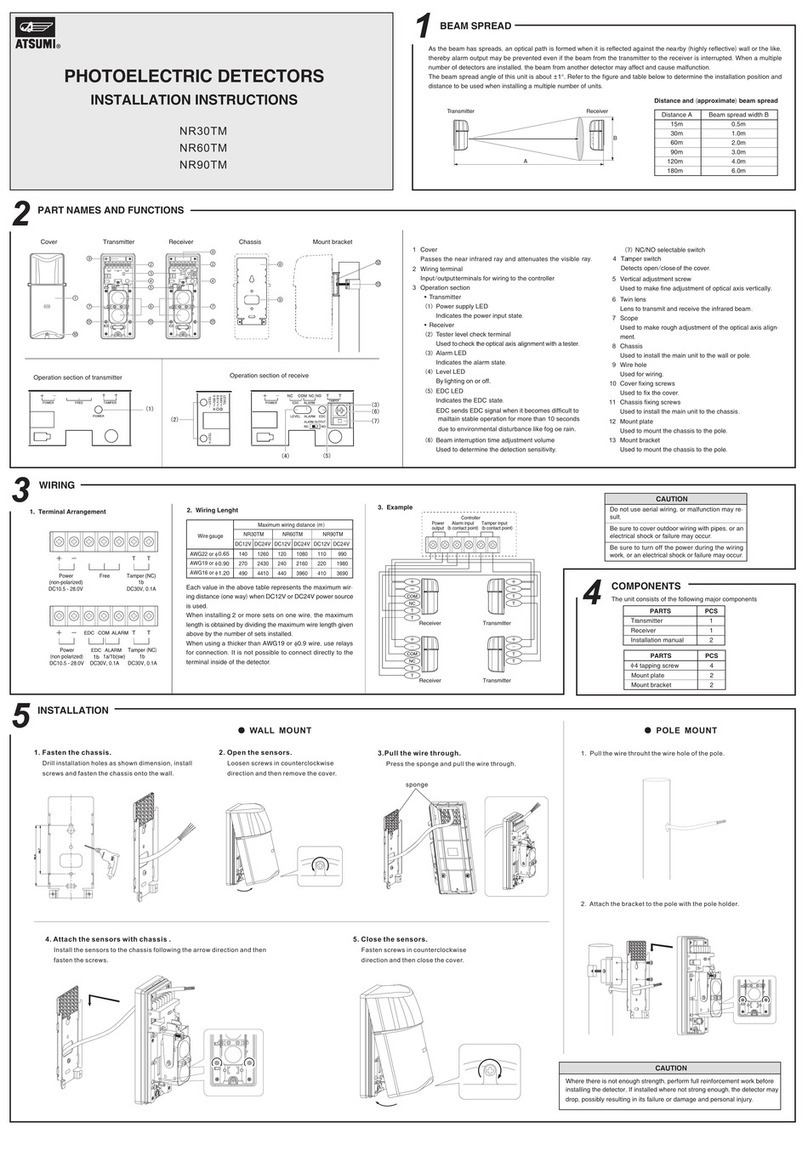
Atsumi Electric
Atsumi Electric NR30TM installation instructions

Morris
Morris 59124 quick start guide
Kemo
Kemo M058N quick start guide

Collingwood Lighting
Collingwood Lighting HBPIR installation instructions
Inovonics
Inovonics D-TECT GJD1030 installation manual
LEGRAND
LEGRAND Wattstopper IDP 3050-A User reference guide

Acconeer
Acconeer A121 user guide

elobau
elobau 153 Series Translation of the original operating instructions

Waeco
Waeco TP-9360 operating manual
B.E.G.
B.E.G. LUXOMAT PD4-M-DIM-SM Installation and operating instruction

General Monitors
General Monitors FL4000 instruction manual
NAPCO
NAPCO GEMC-WL-CO installation instructions
