SPECIFICATIONS
Sensor input: User defined. The supported sensors are listed in Table 01, along
with their maximum ranges.
Thermocouples: Types J, K, R, S, T, N, E and B, to IEC 60584 (ITS-90).
Impedance >> 1 MΩ
Pt100: Excitation: 180 µA, 2 or 3-wire connection (for 2-wire sensors,
tie terminals 2 and 3 together).
α= 0.00385, according to IEC 60751 (ITS-90).
Voltage: 0 to 50 mVdc, 0 to 10 Vdc; Impedance: > 1 MΩ
Current: 0 to 20 mAdc, 4 to 20 mAdc; Impedance: 15.0 Ω(+ 1.9 Vdc)
-150 to 1370 °C / -238 to 2498 ºF
-100 to 760 °C / -148 to 1400 ºF
-50 to 1760 °C / -58 to 3200 ºF
-50 to 1760 °C / -58 to 3200 ºF
-160 to 400 °C / -256 to 752 ºF
-270 to 1300 °C / -454 to 2372 ºF
-90 to 720 °C / -130 to 1328 ºF
500 to 1820 °C / 932 to 3308 °F
-200 to 600 °C / -328 to 1112 ºF
Voltage
Current
Table 01 – Transmitter input sensors
Output: 0 to 10 Vdc, linear with respect to the measured temperature.
Resolution:0.0006 V (14 bits)
Maximum Current (Load): 2 mA
Total Accuracy: 0.25 % of the maximum span for thermocouples, ±1 °C;
0.15 % for Pt100, mA and voltage (for voltage output above 100 mV).
Response Time:< 500 ms
Power Supply:18 to 30 Vdc
Operating Temperature:-40 to 85 °C
Humidity:0 to 90 % UR
Eletromagnetic Compatibility: EN 50081-2, EN 50082-2
Isolation between the sensor and the 4-20 mA loop (1000 V / 1 min).
Internal protection against polarity inversion.
Cold junction compensation for thermocouples.
Housing: ABS plastic. Dimensions: Refer to Fig. 03.
CONFIGURATION
If the transmitter is already configured as required by the application (sensor type,
range, etc), it may be installed and used right away. However, if a distinct
configuration is required, this can be done through the TxConfig software and the
TxConfig Interface.
The TxConfig Interface and Software can be purchased separately one of its
distributors. The latest release of this software can be downloaded from our web site.
Do not save the TxConfig software into a file which contains accent marks. To install,
run the Tx_setup.exe and follow the instructions. To install the configurator, run the
Tx_setup.exe file.
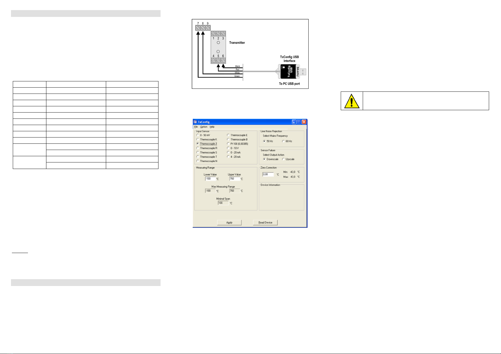
The TxConfig interface connects the transmitter to the PC, as shown in Fig. 01.
Fig. 01 – TxConfig Interface USB connections
Once the connection is accomplished, the software shows the configuration options
of the transmitter model attached. Access the Help for usage instructions.
The TxConfig screen in shown in Fig. 02.
Fig 02 – TxConfig main screen
The fields in the screen mean:
1. Sensor Input: Choose the desired temperature sensor among the available
options. See Table 01.
2. Measuring Range: Defines the output scale for the input sensor. Program here
the measurement Lower Range Value and the Upper Range Value.
When the Lower Range Value is configured with a value higher than the Upper
Range Value the voltage output swings from 10 to 0 V.
The values configured in these fields can not be beyond the sensor measuring
range. The minimum span value has to be observed as well (see Table 01).
3. Line Noise Rejection: The transmitter incorporates a digital filter to cancel the
induced noise from the 50 or 60 Hz systems. For better performance, select the
line frequency used in your country.
4. Sensor Failure Detection: Establishes the transmitter output behavior (upscale or
down-scale) in the presence of a sensor fail..
5. Zero Correction: Allows for small sensor corrections.
6. Device Information: The Device Information box contains relevant data
concerning a particular transmitter. Please pass along this information when
contacting the technical assistance department.
7. Apply: Sends a new configuration to the transmitter.
8. Read Configuration: Brings to the screen the Transmitter parameters
configuration.
Note: The factory default configuration is (unless otherwise specified or ordered):
Pt100 input, 0 to 100 °C
60 Hz filtering and upscale (20 mA) output for sensor fail.
During the configuration, the transmitter requires to be powered. Depending on the
PC used, the power can be supplied by the serial port. To assure proper
communication, it is recommended to apply external power to the transmitter.
The TxConfig interface has a complex electronic circuit. D
other interface or cable connection to USB
; the product will be damaged
and this damage is not covered under warranty.
It is important to follow the recommendations below
•Signal wires should be installed in grounded conduits and away from power or
contactor wires.
•The instrument should have its own power supply wires, which should not be
shared with electrical motors, coils, contactors, etc.
•Installing RC filters is strongly recommended at contactor coils or any other
inductors.
•System failure should always be taken into account when designing a control
panel to avoid irreversible damage to equipment or people.


