manuals.online logo
Brands
  1. Home
  2. •
  3. Brands
  4. •
  5. Novus
  6. •
  7. Measuring Instrument
  8. •
  9. Novus LoopView-N User manual

Novus LoopView-N User manual

NOVUS AUTOMATION 1/4
CURRENT LOOP INDICATOR – LOOPVIEW-N MODEL
INSTRUCTION MANUAL V1.0x B
SECURITY ALERTS
The symbols below are used throughout this manual to draw the
user’s attention to important information regarding safety and use of
the device.
CAUTION:
Read the manual thoroughly
before installing and operating
the device
CAUTION OR DANGER:
Risk of electric chock
Safety recommendations must be followed to ensure user safety and
to prevent damage to the device or system. If the device is used in a
manner other than that specified in this manual, the safety
protections may not be effective.
INTRODUCTION
The LoopView indicator measures the electrical current circulating in
a current loop and displays values proportional to the measured
current. It obtains the electrical energy necessary for its operation
from the electrical current circulating in the control loop, without
affecting the value of this current.
LoopView is suitable to receive in its female connector 2-wire type
transmitters (sink) whose connection is in DIN EN 175301-803 A
standard.
The relationship between the measured current value and the
respective value shown in the display is established by defining the
Indication Range. For the definition of the indication range, the
values to be shown in the display must be entered for the current
value 4 mA (
IN.ll
) and the current value 20 mA (
IN.Kl
).
PRESENTATION
The indicator frontal panel can be seen in Figure 01:
Figure 01 – Overview of LoopView
Display: It shows the measured variable, the configuration
parameters and its respective values and conditions.
and Navigation Keys: It allows you to change the
parameters values and access the configuration cycles and
calibration of the indicator.
FUNCTIONAL FEATURES
LoopView has the following functional features:
•Adjustable indication range;
•Increasing or decreasing indication;
•Adjustable decimal point;
•Adjustable Offset;
•Adjustable digital filter;
•Display alarms: minimum value, maximum value or out of range
values;
•Factory calibration repair;
•Configuration protection with password.
OPERATION
By simultaneously pressing the keys + simultaneously,
several configuration parameters will be displayed sequentially. The
keys must be released in the desired parameter.
When you release the keys in the desired parameter, it will be
displayed. Its current value is also displayed.
The + keys allow to make desired changes in current
value of the parameter. To save the new set value, simply press the
+ keys simultaneously, returning to sequential display of
the configuration parameters.
STARTUP
LoopView must be installed in a previously validated process loop
with a power supply and a properly operating 4-20 mA transmitter in
order to establish an electrical current proportional to the measured
variable (PV): temperature, pressure, flow rate, etc.
Under the above conditions, when the power supply is turned on,
LoopView will display a value proportional to the measured electrical
current and according to the current configuration. If necessary, a
new configuration must be made at this time, align with process
characteristics.
The configuration consists of setting appropriate values for the
several parameters of the indicator that together determine its
operation mode. The parameters are displayed in the same order as
the indicator.
CONFIGURATION PARAMETERS
dp.po
Decimal Point.
It allows you to determine the position of the
decimal point the indication range configuration.
IN.ll
Lower limit of the indication range.
It allows you to determine the value set for the
display corresponding to the current value 4 mA.
IN.Kl
Upper limit of the indication range.
It allows you to determine the value set for the
display corresponding to the current value 20 mA.
LoopView
NOVUS AUTOMATION 2/4
0ffs
Offset.
Function that allows changes or corrections to the
PV value displayed by the indicator.
Filt
Filter
.
Parameter that defines the value of the filter
applied to the signal processing. Used to improve
the stability of the measured signal.
Configurable with values between 0 and 9 (Value
in seconds of the filter 1).
FvaL
Alarm Function.
LoopView has the ALARM function to indicate
that process critical PV values have been reached.
When a PV value defined as critical is measured
by the indicator, the d
isplay interpolates the
presentation of PV value with
AL
message.
The PV value critical to the process is set in
SPAL
parameter.
Three alarm functions are available:
LO
The display should indicate that the PV
value is BELOW the critical value that
has been set (
spaL
).
KI
The display should indicate that the PV
value is ABOVE the critical value that
has been set (
spaL
).
IErr
The display should indicate that the PV
value is out of the defined measuring
range.
Off
Critical value indication is disabled.
spaL
Alarm Setpoint.
It allows you to set the PV value critical to the
process used for alarm indication.
This parameter will not be displayed when Alarm
Function is set to
Off
or
IErr
.
pass
Password.
It allows you to enter the access password. This
will allows you to change the configuration
parameters according to the protection rule set in
the Protection parameter.
Without the password, the configuration can only
be viewed.
(alib
Enable Calibration.
It allows you to calibrate the indicator, showing the
necessary parameters for the procedure
(
INL(
,
INx(
and
Rstr
).
no
Calibration disabled.
yes
Calibration enabled.
When the calibration is not enabled, the
parameters related to this procedure will not be
displayed.
INL(
Lower Calibration Value.
Declaration of the lower calibration value.
INx(
Higher Calibration Value.
Declaration of the higher calibration value.
rstr
Calibration Restore
It allows you to retrieve the last calibration
performed.
no
Do not retrieve the last calibration.
yes
YES, retrieve the last calibration.
pas.(
Setting a new access password.
It allows you to set a new access password,
always different from zero.
prot
Configuration protection.
It allows you to set the level of protection to be
adopted by the indicator.
1
Only special parameters are protected.
2
All parameters are protected.
sn.x
Indicator serial number (Higher part).*
HIGHER part of the indicator serial number.
sn.l
Indicator serial number (Lower part).*
LOWER part of the indicator serial number.
* Serial number composition: 8888 8888 (
sn.x
sn.l
)
LoopView
NOVUS AUTOMATION 3/4
CONFIGURATION PROTECTION
The indicator allows the protection of the configuration created by the
user, preventing improper changes in the values of the configuration
parameters.
You can always view the parameters. To make changes, you must
enter the password in the
PASS
parameter. You can change the
parameters if the password is correct. You cannot make changes if
the password is not correct.
LoopView allows two different levels of protection: Protection for all
configuration parameters or protection for a special group of
parameters, defined as Special Configuration Parameters. These
parameters are always protected because they are relevant to the
operation of the indicator.
CONFIGURATION
PARAMETERS
Dp.po
INLl
INxl
0ffs
Filt
spaL
blal
pass
(alib
SPECIAL CONFIGURATION
PARAMETERS
INL(
INx(
rstr
pas.(
prot
sn.x
sn.l
Table 01 – Configuration parameters
The Protection parameter (
PROt
) determines the protection level to
be adopted, according to the table below:
PROTECTION
LEVEL PROTECTED CYCLES
1
Only Special Configuration Parameters are
protected.
(Indicator factory setting condition).
2 All parameters are protected.
Table 02 – Configuration protection levels
ACCESS PASSWORD
When accessed, the protected cycles require the Access Password.
If entered correctly, the password will allow changes to be made to
the configuration of the parameters of these cycles.
The access password must be entered in the Access Password
(
PASS
) parameter, shown in the first of the protected cycles. Without
the access password, the parameters of the protected cycles can
only be viewed.
The indicator leave factory with the access password set to
1111.
MASTER PASSWORD
The Master Password is intended for allowing the user to define a
new password in the event of it being forgotten. The Master
Password doesn’t grant access to all parameters, only to the
Password Change parameter (
PAS.(
). It enables you to set a new
password for the indicator.
The master password is made up by the last three digits of the serial
number of the controller added to the number 9000.
As an example, for the equipment with serial number 07154321, the
master password is 9 3 2 1.
The serial number of the indicator is available in the
sn.x
and
sn.l
parameters.
ELECTRICAL CONNECTIONS
The indicator has standard EN 175301-803 (formerly DIN 43650) male and female connectors, located at the top and bottom of the device. It is also
has internal protection against inversion of the polarity of the supply voltage.
Figure 02 shows the required connections:
Figure 02 – Electrical connection
NOVUS AUTOMATION 4/4
RECOMMENDATIONS FOR THE INSTALLATION
Installation, operation, and maintenance must only be carried out by
qualified personnel and in accordance with the information provided
in this manual. Any deviation from these instructions will be the sole
responsibility of the client.
Normal safety precautions should be taken to avoid the possibility of
an accident occurring when operating under high pressure and/or
high temperature conditions.
Do not connect the power supply until the entire installation is
complete.
CALIBRATION
The indicator leaves the factory calibrated and ready for use.
Recalibration is a procedure that is not recommended for
inexperienced operators.
You should consider using the recovery feature of the last performed
calibration (
rstr
). If no other calibration has been performed, the
factory calibration is still available.
If the calibration is actually required, you should proceed as follows:
1. Provide a power generator with accuracy compatible with the
measurement accuracy specification of the indicator.
2. Connect the generator to the indicator according to Figure 03:
Figure 03 – Power generator
3. Set a current of 12 mA in the power generator.
4. Set a value for the
inLL
parameter (the value must be lower
than the defined value set for
nxL
).
5. Enter the correct password.
6. Change the
Prot
parameter to
2
and thus allow changes in all
configuration parameters.
7. Change the
(alib
parameter to
YES
and thus enable the
calibration and its parameters.
8. Access the
INL(
parameter.
9. Set a current of 4 mA in the power generator.
10. Set the value of parameter
INL(
so that it reads -1999.
11. Access the
INx(
parameter.
12. Set a current of 20 mA in the power generator.
13. Set the value of
INx(
parameter so that it indicates 9999.
14. Validate the calibration mode.
MECHANICAL INSTALLATION
Figure 04 provides information on the dimensions of the indicator:
Figure 04 – Dimensions
SPECIFICATIONS
DIMENSIONS:...............................................................See Figure 04
Approximate Weight: ...............................................................54 g
ENVIRONMENTAL CONDITIONS:
Operating Temperature: ............................................ -40 to 85 °C
POWER SUPPLY...........................................Loop current 4 to 20 mA
MAXIMUM LOOP CURRENT .................................................... 60 mA
INDICATION RANGE ...........................-1999 to 9999 / 9999 to -1999
DISPLAY RESOLUTION ............... 11998 levels (from -1999 to 9999)
ACCURACY OF THE INDICATED VALUE..........................................
..........................................................0.1 % of span ± 1 digit (@ 25°C)
SAMPLING RATE.....................................................................100 ms
THERMAL COEFFICIENT.................................. 0.005 % / °C of span
VOLTAGE DROP AT THE INDICATOR:..............................................
< 10 mA: .............................................................................< 5.4 V
10 to 12 mA: .......................................................................< 3.9 V
> 12 mA: .............................................................................< 2.6 V
HOUSING..................................................ABS (Polyurethane gasket)
PROTECTION.............................................................. IP65, NEMA4X
CERTIFICATION..............................................................................CE
IDENTIFICATION
LoopView Basic version
WARRANTY
Warranty conditions are available on our website
www.novusautomation.com/warranty.

Other Novus Measuring Instrument manuals

Novus NVR-4108-H1 User manual

Novus

Novus NVR-4108-H1 User manual

Novus fieldlogger User manual

Novus

Novus fieldlogger User manual

Novus NHDR-4304-H1 User manual

Novus

Novus NHDR-4304-H1 User manual

Novus N CONTROL 4000 User manual

Novus

Novus N CONTROL 4000 User manual

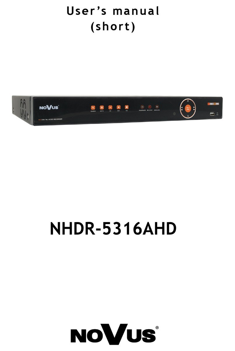
Novus NHDR-5316AHD User manual

Novus

Novus NHDR-5316AHD User manual

Novus NVR-4204P4-H1/F User manual

Novus

Novus NVR-4204P4-H1/F User manual

Novus NP400 User manual

Novus

Novus NP400 User manual

Novus LogBox Wi-Fi Instruction sheet

Novus

Novus LogBox Wi-Fi Instruction sheet

Novus N320 User manual

Novus

Novus N320 User manual

Novus NVR-6332-H8/FR User manual

Novus

Novus NVR-6332-H8/FR User manual

Novus NVR-6232-H2 User manual

Novus

Novus NVR-6232-H2 User manual

Novus NVR-6408-H1/F-II User manual

Novus

Novus NVR-6408-H1/F-II User manual

Novus N1500FT User manual

Novus

Novus N1500FT User manual

Novus NVR-7308P8-H2 User manual

Novus

Novus NVR-7308P8-H2 User manual

Novus N1500FT User manual

Novus

Novus N1500FT User manual

Novus NHDR-6016-H1-II User manual

Novus

Novus NHDR-6016-H1-II User manual

Novus NVR-6316A-H1-II User manual

Novus

Novus NVR-6316A-H1-II User manual

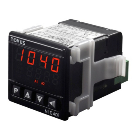
Novus N1040i User manual

Novus

Novus N1040i User manual

Novus LogBox BLE User manual

Novus

Novus LogBox BLE User manual

Novus 6000 Series User manual

Novus

Novus 6000 Series User manual

Novus NVR-6316A-H2-II User manual

Novus

Novus NVR-6316A-H2-II User manual

Novus NVR-6304P4A-H1-II User manual

Novus

Novus NVR-6304P4A-H1-II User manual

Novus NHDR-6116-H2-II User manual

Novus

Novus NHDR-6116-H2-II User manual

Novus NHDR-4104-H1 User manual

Novus

Novus NHDR-4104-H1 User manual

Popular Measuring Instrument manuals by other brands

Selec MV Series operating instructions

Selec

Selec MV Series operating instructions

Agilent Technologies varian 310-MS LC/MS Pre-installation instructions

Agilent Technologies

Agilent Technologies varian 310-MS LC/MS Pre-installation instructions

WIKA FLC-2300 operating instructions

WIKA

WIKA FLC-2300 operating instructions

Endress+Hauser Promass 40 operating instructions

Endress+Hauser

Endress+Hauser Promass 40 operating instructions

Epever MT75 user manual

Epever

Epever MT75 user manual

Hach NA5600 sc Na+ Maintenance and troubleshooting

Hach

Hach NA5600 sc Na+ Maintenance and troubleshooting

Rixen M-700S Operation manual

Rixen

Rixen M-700S Operation manual

Kitchen Brains BB4 operating manual

Kitchen Brains

Kitchen Brains BB4 operating manual

International Light Technologies ILT10C manual

International Light Technologies

International Light Technologies ILT10C manual

Macurco AimSafety PM400 User instructions

Macurco

Macurco AimSafety PM400 User instructions

Concoa 5803007 Installation and operation instructions

Concoa

Concoa 5803007 Installation and operation instructions

Abbott CELL-DYN 3200 System Operator's manual

Abbott

Abbott CELL-DYN 3200 System Operator's manual

Vaisala WAC151 user guide

Vaisala

Vaisala WAC151 user guide

PCB Piezotronics 357B34 Installation and operating manual

PCB Piezotronics

PCB Piezotronics 357B34 Installation and operating manual

Shodex RSpak KC-811 Operation manual

Shodex

Shodex RSpak KC-811 Operation manual

Toho Electronics TRM20A Operation manual

Toho Electronics

Toho Electronics TRM20A Operation manual

MAXPhotonics MFP-5W user guide

MAXPhotonics

MAXPhotonics MFP-5W user guide

RTI Cobia Flex R/F user manual

RTI

RTI Cobia Flex R/F user manual

manuals.online logo
manuals.online logoBrands
  • About & Mission
  • Contact us
  • Privacy Policy
  • Terms and Conditions

Copyright 2025 Manuals.Online. All Rights Reserved.