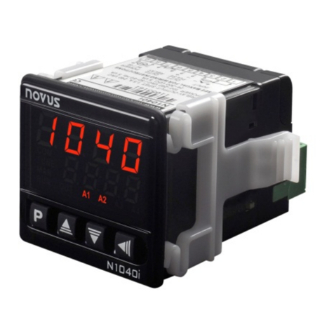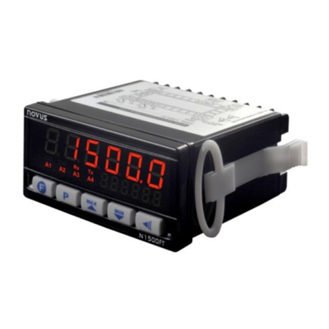
N1500 Digital Panel Meter
NOVUS AUTOMATION 7/8
CALIBRATION LEVEL
All input and output types are factory calibrated. This level
should only be accessed by experienced personnel. If this level
is accidentally accessed do not touch the or keys, just
press the key a few times to go back to the Work Level.
Input low calibration.Sets the Process Variable
low calibration (offset).
Several keystrokes at or
necessary to increment one digit.
Input high calibration.Sets the Process Variable
span calibration (gain).
Analog output low calibration. Sets the analog
current output low calibration (offset).
Analog output span calibration. Sets the analog
current output high calibration (span) of the analog
output (20 mA).
Cold Junction calibration
.
calibrate the cold junction temperature (at the input
terminals) directly in degrees.
Hardware type. This parameter adapts the firmware
to the actual hardware (optional features) and should
not be changed by the user.
2 Alarms .................................................3
2 Alarms and 4-20 mA .........................19
2 Alarms and RS485 ............................35
2 Alarms, 4-20 mA, and RS485 ...........51
4 Alarms ...............................................15
4 Alarms and 4-20 mA .........................31
4 Alarms and RS485 ............................47
4 Alarms, 4-20 mA, and RS485........... 63
CONFIGURATOR SOFTWARE
Available for free download from the NOVUS website, QuickTune
software is the ideal tool to configure the N1500. It also has
diagnostic tools.
To configure the device, simply follow the procedure below:
1. Download and install the software on the computer to be used.
2. Run QuickTune, set up communication and start device
recognition.
PROBLEMS WITH THE DIGITAL PANEL METER
Connection errors or improper configuration will result in
malfunctioning of the digital panel meter. Carefully revise all cable
connections and programming parameters before operating the unit.
Some error messages will help the user identify potential problems.
MESSAGE POSSIBLE PROBLEM
Measured value is above the value allowed for the
selected sensor or above the configured input
signal limit.
Measured value is below the value allowed for the
selected sensor or below the configured input
signal limit.
Open input. No sensor is connected,
sensor is broken.
Pt100 cable resistance is too high, or the sensor
is badly connected.
Figure 11 –Error messages
Different messages other than the ones above should be reported to
the manufacturer. Please inform the serial number if this should
occur. The serial number can be viewed at the display by pressing
the key for about 3 seconds.
The software version of the instrument can be viewed at the time the
unit is powered.
When not properly configured, the instrument may show false error
messages, particularly those related to the type of input selected.
SPECIAL RECOMMENDATIONS
Should the digital panel meter be repaired, some special handling care
should be taken. The device must be withdrawn from the case and
immediately placed in an anti-static wrap; protected from heat and
humidity.
INPUT CALIBRATION
All inputs are factory calibrated and recalibration should only be done
by qualified personnel. If you are not familiar with these procedures
do not attempt to calibrate this instrument.
The calibration steps are:
a) Select the input type to be calibrated.
b) Set the desired upper and lower display limits.
c) At the input terminals inject an electrical signal corresponding to
a known indication value a little higher than the lower display
limit.
d) Select the inLC prompt. Through the and keys adjust
PV so that it matches the injected signal.
e) Inject a signal that corresponds to a value a little lower than the
upper limit of the display.
f) Select the inkC prompt. Through the and keys adjust
PV so that it matches the injected signal.
g) Repeat steps c) to f) until no further adjustment is necessary.
Note: When verifications are proceeded, note if the Pt100
excitation/activation current the calibrator requires is compliant to the
Pt100 excitation current used in this instrument: 0.750 mA.
SERIAL COMMUNICATION
The digital panel meter can be supplied with an asynchronous
RS485 digital communication interface for master-slave connection
to a host computer (master).
The digital panel meter works as a slave only and all commands are
started by the computer which sends a request to the slave address.
The addressed unit processes the command and sends back the
answer.
Broadcast commands (addressed to all units in a multidrop network)
are accepted but no response is generated.
FEATURES
•RS485 compatibility with two-wire bus from the host to up to 31
slaves in a multidrop network topology.
•Up to 247 units can be addressed by the MODBUS RTU protocol.
•Maximum network distance: 1000 m.
•Disconnection time: Maximum of 2 ms after the delivery of the last
byte.
•Communication signals electrically isolated from the rest of the
instrument.
•Baud rate: 1200, 2400, 4800, 9600, 19200, 38400 or 57600 bps.
•Number of data bits: 8, without parity.
•Number of stop bits: 1
•Time to start response transmission: 100 ms maximum delay
after acknowledging the command.
•Protocol: MODBUS (RTU)
Two parameters must be configured to use the serial communication
interface: Communications Baud Rate (bavd) and the
Communication Address (adres).

