N1040i Digital Panel Meter
NOVUS AUTOMATION 2/7
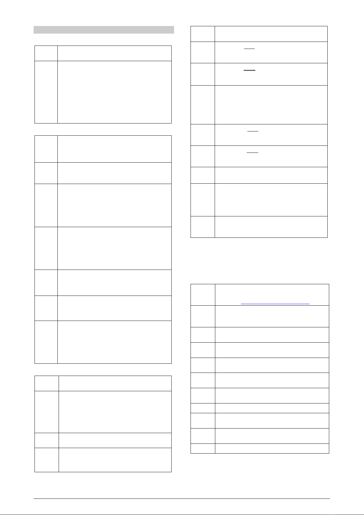
Alarm of the maximum differential value. It triggers when
the PV value is above the point defined by:
+
(using alarm 1 as an example).
SPA1 positive SPA1 negative
Alarms of the Sensor Break. It is activated when the
Input presents problems such as interrupted sensor, bad
connection, etc.
Table 2 –Alarm functions
Note: The figures are also valid for Alarm 2 (SPA2).
Important note: Alarms configured with the ki, dif and dif.k
functions also trigger their associated output when a sensor fault is
identified and signaled by the digital panel meter. A relay output, for
example, configured to function as a High Alarm (ki), will operate
when the SPAL value is exceeded and when the sensor connected
to the digital panel meter input is broken.
ALARM INITIAL BLOCKING
The initial blocking option inhibits the alarm from being recognized
if an alarm condition is present in the process when the digital panel
meter is turned on. The alarm will be enabled only after the
occurrence of no alarm condition.
The initial blocking is useful, for example, when one of the alarms is
configured as a minimum value alarm, which can cause the alarm to
be triggered as soon as the process is started (often undesired
behavior).
The initial blocking is not valid for theierr (Sensor Break) function.
OFFSET
Feature that enables you to make small adjustments to the PV
indication. Allows to correct measurement errors that appear, for
example, when replacing the temperature sensor.
USB INTERFACE
The USB interface is used to CONFIGURE, MONITOR or UPDATE
the controller FIRMWARE. You should use QuickTune software,
which offers features to create, view, save and open settings from
the device or files on the computer. The tool for saving and opening
configurations in files allows you to transfer settings between devices
and perform backup copies.
For specific models, QuickTune allows to update the controller
firmware (internal software) via the USB interface.
For MONITORING purposes, you can use any supervisory software
(SCADA) or laboratory software that supports the MODBUS RTU
communication over a serial communication port. When connected to
a computer USB, the controller is recognized as a conventional serial
port (COM x).
You must use QuickTune software or consult the DEVICE
MANAGER on the Windows Control Panel to identify the COM port
assigned to the controller.
You should consult the mapping of the MODBUS memory in the
controller communication manual and the documentation of the
supervision software to start the MONITORING process.
Follow the procedure below to use the USB communication of the
device:
1. Download QuickTune software from our website and install it on
the computer. The USB drivers necessary for operating the
communication will be installed with the software.
2. Connect the USB cable between the device and the computer.
The controller does not have to be connected to a power supply.
The USB will provide enough power to operate the
communication (other device functions may not operate).
3. Run QuickTune software, configure the communication and
start the device recognition.
The USB interface IS NOT ISOLATED
signal input (PV) or the digital inputs and outputs. It is
intended for temporary use during CONFIGURATION
and MONITORING periods.
For the safety of people and devices, it must only be
used when the device is completely disconnected
from the input/output signals.
Using the USB in any other type of connection is
possible but requires a careful analysis by the person
responsible for installing it.
When MONITORING for prolonged periods and with
connected inputs and outputs, it is recommended to
use
the RS485 interface, which is available or
optional in most of NOVUS products.
PV RETRANSMISSION
The digital panel meter may include an analog output which performs
the retransmission of the values of PV into a signal of 0-20 mA or 4-
20 mA. The analog retransmission can be scaled, i.e., there are
minimum and maximum limits to establish the retransmission range,
defined in the rtLL and rtkL parameters.
The analog output is available on terminals 13 and 14 for models
N1040i-RA and N1040i-RA-485.
To obtain retransmission in electrical voltage, you must install a
shunt resistor (500 Ω max.) across the analog output terminals. This
resistor value depends on the desired voltage range.
The analog retransmission output is not electrically isolated from the
RS485 serial communication.
24 Vdc AUXILIARY VOLTAGE SOURCE
Another feature that may be available in the digital panel meter is an
auxiliary power supply for exciting field transmitters (two-wire 4-20
mA transmitters).
The 24 Vdc output is on terminals 13 and 14 for models N1040i-RE
and N1040i-RE-485.
The 24 V auxiliary power supply is not electrically isolated from the
RS485 serial communication.
INSTALLATION / CONNECTIONS
The digital panel meter shall be fastened on a panel, following the
sequence of steps described below:
•Make a 46 x 46 mm cutout in the panel.
•Remove the mounting clip from the digital panel meter.
•Insert the digital panel meter.in the cutout from the front of the
panel.
•Replace the clip on the digital panel meter, pressing until you get
a tight hold.
ELECTRICAL CONNECTIONS
Figure 1 shows the layout of the features on the rear panel of the
digital panel meter:
Figure 1 –Inputs connections and power supply