Novus DC80T User manual

1
INDEX
1. INTRODUCTION...........................................................................................1
2. SAFETY INFORMATION..............................................................................2
3. MODEL DC80T.............................................................................................2
3.1. MODEL DC80T GENERAL SPECIFICATIONS.....................................3
3.2. MODEL DC80T FRONT PANEL............................................................3
3.3. MODEL DC80T OPERATING INSTRUCTIONS....................................4
4. MODEL DC80R.............................................................................................5
4.1. MODEL DC80R GENERAL SPECIFICATIONS....................................6
4.2. MODEL DC80R FRONT PANEL ...........................................................6
4.3. MODEL DC80R OPERATING INSTRUCTIONS...................................7
5. MODEL DC80L.............................................................................................8
5.1. MODEL DC80L GENERAL SPECIFICATIONS.....................................9
5.2. MODEL DC80L FRONT PANEL............................................................9
5.3. PROTECTION......................................................................................10
5.4. MODEL DC80L OPERATING INSTRUCTIONS..................................10
6. MAINTENANCE..........................................................................................13
1.INTRODUCTION
The Novus Calibrators series DC80 are portable instruments designed to meet the
user needs for measuring and simulating signals such as voltage, current,
resistance, thermocouples and RTDs. The available options depend on the
particular model. They are:
•DC80T, for Thermocouples and mV
•DC80R, for RTDs and resistance
•DC80L, for linear mV, V and mA (provides internal power supply for
powering 2-wire transmitters)

2
2.SAFETY INFORMATION
To avoid possible electric shock or personal injury:
•Use the Calibrator only as specified in this manual, or the protection provided
by the Calibrator might be impaired.
•Do not apply more than the rated voltage between the terminals, as marked on
the Calibrator, or between any terminal to earth.
•Make sure the battery door is closed and latched before operating the
calibrator.
•Remove test leads from the calibrator before opening the battery door.
•Inspect the Calibrator before using it. Do not use the Calibrator if it appears
damaged.
•Do not operate the calibrator around explosive gas, vapor, or dust.
To avoid possible damage the calibrator or system, make sure to use the right
connector and select the appropriate range before using the instrument for
measurement or simulation.
3.MODEL DC80T
The MODEL DC80T is capable of measuring and generating mV and
thermocouple signals. The specifications shown on the tables below are valid for
the period of one year, at ambient temperatures between 18~28 °C.
INPUT/OUTPUT RANGE
RESOLUTION
ACCURACY
-10 mV to 75 mV 0.01 mV ± (0.025% + 2 counts)
Measurementand Simulation specifications for Thermocouples:
Type
Range Resolution Accuracy Tamb Error (*)
J -200 to 1200 °C / -
328 to 2192 °F
0.1 °C / ºF ±(0.15 % Span) ±0.5 ºC
K -200 to 1370 °C / -
328 to 2498 °F
0.1 °C / ºF ±(0.15 % Span) ±0.5 ºC
T -200 to 400 °C /-328 to752 °F 0.1 °C / ºF ±(0.15 % Span) ±0.5 ºC
E -200 to 950 °C /-328 to1742 °F 0.1 °C / ºF ±(0.15 % Span) ±0.5 ºC
R -20 to 1750 °C / -4 to 3182 °F 1 °C / ºF ±(1 ºC + 10 µV) ±0.5 ºC
S -20 to 1750 °C / -4 to 3182 °F 1 °C / ºF ±(1 ºC + 10 µV) ±0.5 ºC
B
600 to 1800 °C/ 1112 to 3272 °F
1 °C / ºF ±(1 ºC + 10 µV) ±0.5 ºC
N -250 to 1300 °C / -
418 to 2372 °F
0.1 °C / ºF ±
(0.3 ºC +10 µV)
±0.5 ºC
- (*) Tamb Error is the accuracy of internal ambient temperature sensor
- Maximal input voltage: 30 Vpp.

3
3.1. MODEL DC80T GENERAL SPECIFICATIONS
Maximum voltage allowed between any terminal and earth ground or between the
two input terminals: ............................................................................................30 V
Storage temperature:........................................................................-40 °C ~ 60 °C
Operating temperature:.........................................................................0 °C ~ 50 °C
Operating altitude:.................................................................3000 meters maximum
Temperature coefficient:...............±0.02 % / °C on 0 °C ~ 18 °C and 28°C ~ 50 °C
Relative humidity:...........................................................................95 % up to 30 °C
........................................................................................................75 % up to 40 °C
........................................................................................................45 % up to 50 °C
Shock:...........................................................................Random 2 g, 5 Hz to 500 Hz
Safety:............................................................................................1 meter drop test
Power requirements:...............................................................6 x AAA 1.5 V Battery
Size:.................................................................................205 mm x 98 mm x 46 mm
Weight:.....................................................................................472 g (with batteries)
3.2. MODEL DC80T FRONT PANEL
The keypad and display functions are shown below:
Input connector
Output connector
Power ON / OFF switch
Input type selection key
°C / °F key
INPUT/OUTPUT selection key
Fast increment key
Fast decrement key
Increment key
Decrement key
Low battery indication
Input mode indication
Output mode indication
Reading value
Unit (°C / °F / mV) indication
Thermocouple type indication

4
3.3. MODEL DC80T OPERATING INSTRUCTIONS
In thermocouple temperature simulation the calibrator generates the voltage as an
actual thermocouple, considering both the simulated temperature (hot joint) and
connection temperature (cold joint). To ensure stated accuracy the user must use
a connection cable between calibrator and calibrated device with the same
thermoelectric properties of the selected thermocouple (extension or
compensation cable).
A K type extension cable (yellow connector) is supplied with the calibrator and
should only be used for K type calibration for maximum accuracy.
Make sure that the appropriate cable with the correct polarity is being used to
avoid large calibration errors.
Thermocouple or mV measurement
1. Press the power switch to turn
on the calibrator.
2. Pressthe INPUT / OUTPUT key
to select INPUT mode.
3. Press the TC TYPE selection key
to configure the instrument to the
desired input type
4. Connect the T/C or mV signal to the
input connector .
5. The measured value is presented in
.
Thermocouple or mV Simulation
1. Press the power switch to
turn on the calibrator.
2. Press the INPUT / OUTPUT key
to select OUTPUTmode.
3. Press the TC TYPE selection
key to configure the desired
output signal type.
4.
Press the increment /
decrement keys
to adjust the value to be
simulated.
5.
The simulated signal is
de
livered at the output
connector .
6. To change output values, press
the increment / decrement keys
until the desired value is
presented in the display.
Changing to other input types is
accomplished by the TC TYPE
selection key .

5
4.MODEL DC80R
The MODEL DC80R RTD Process Calibrator measures and simulates resistance
values of 7 distinct types of RTDs, either in °C or °F. Simultaneous measurement
and signal simulation is not provided.
The specifications are valid for the period of one year, at temperatures between
18~28 °C.
Resistance measurement and simulation specifications:
Range Measurement accuracy
( 4 W ± Ω ) Simulate
Accuracy ( ± Ω ) Excitation
current (mA)
0.00 Ω ~ 400.00 Ω0.1 0.15 0.1 ~ 0.5
0.1 0.5 ~ 3.0
400.0 Ω ~ 1500.0
Ω0.5 0.5 0.05 ~ 0.8
1500.0 Ω ~
3200.0 Ω1 1 0.05 ~ 0.4
2
The excitation current applies only to the simulation mode. The excitation current
is provided by the target instrument (OHM meter of RTD meter) connected to the
calibrator.
RTD measurement and simulation specifications:
Mode Range
Accuracy ( °C ) Excitation
current (mA)
Input
4 W Input
2 W / 3 W Output
Pt10 385 -200 ~ 800 °C /
-328 ~ 1472 °F NOT SPECIFIED 0.1 ~ 3.0
Pt50 385 -200 ~ 800 °C /
-328 ~ 1472 °F 0.7 1.0 0.7 0.1 ~ 3.0
Pt100385 -200 ~ 800 °C /
-328 ~ 1472 °F 0.33 0.5 0.33 0.1 ~ 3.0
Pt200385
-200 ~ 250 °C /
-328 ~ 482 °F 0.2 0.3 0.2 0.1 ~ 3.0
250 ~ 630 °C /
482 ~ 1166 °F 0.8 1.6 0.8
Pt500 385
-200 ~ 500 °C /
-328 ~ 932 °F 0.3 0.6 0.3 0.05 ~ 0.8
500 ~ 630 °C /
932 ~ 1166 °F 0.4 0.9 0.4
Pt1000
385
-200 ~ 100 °C /-
328 ~ 212 °F 0.2 0.4 0.2 0.05 ~ 0.8
100 ~ 630 °C
/212 ~ 1166 °F 0.2 0.5 0.2
Pt100 JIS -200 ~ 630 °C /
-328 ~ 1166 °F 0.3 0.5 0.3 0.1 ~ 3.0
The excitation current applies only to the simulate mode. The excitation current is
provided by the target instrument (OHM meter of RTD meter) connected to the
calibrator.

6
4.1. MODEL DC80R GENERAL SPECIFICATIONS
Maximum voltage allowed between any terminal and earth ground or between the
two input terminals: ............................................................................................30 V
Resolution: .................................................RTD 0.1 °C / °F; Resistance 0.01 / 0.1 Ω
Storage temperature:........................................................................-40 °C ~ 60 °C
Operating temperature:.....................................................................-10 °C ~ 55 °C
Operating altitude:.................................................................3000 meters maximum
Temperature coefficient:................±0.01 % / °C (0 °C ~ 18 °C and 28 °C ~ 50 °C)
Relative humidity:............................................................................95 % upto 30 °C
....................................................................................................................... 75 %up to40 °C
....................................................................................................................... 45 %up to50 °C
........................................................................................................35 % up to 55 °C
Shock:...........................................................................Random 2 g, 5 Hz to 500 Hz
Safety:............................................................................................1 meter drop test
Power requirements:...............................................................6 x AAA 1.5 V Battery
Size:.................................................................................205 mm x 98 mm x 46 mm
Weight:.............................................................................472 g (including batteries)
4.2. MODEL DC80R FRONT PANEL
The keypad and display functions are shown below:
4-wire input terminal (not used
for output)
2-wire input/ output terminal
3-wire input terminal (not used
for output)
Power ON / OFF switch
RTD type selection key
°C / °F selection key
INPUT/OUTPUT selection key
Fast increment key (simulation) /
wire mode selection
(measurement)
Fast decrement key (simulation) /
wire mode selection
(measurement)
Increment key
Decrement key
Low battery indication
INPUT mode indication
OUTPUT mode indication
Reading (measurement) value
indication
Unit (°C / °F) indication
Input type indication
Accessories included: 2 pairs of test leads and alligator clips

7
4.3. MODEL DC80R OPERATING INSTRUCTIONS
RTD measurement
1. Press the power switch to
turn ON the calibrator.
2. Press the INPUT / OUTPUT key
to select INPUT mode.
3. Press RTD mode key for
selecting the RTD type.
4. Connect the RTD or Resistance
to the input connector.
5. For 3 W / 4
W mode
measurements, press the wire
mode select key and to
select the desired mode. Then
wire the signal to the
corresponding input terminal.
6. Get the reading value .
RTD Simulation
1. Press the power switch to
turn ON the calibrator.
2. Press the INPUT / OUTPUT key
to select OUTPUT mode.
3. Press RTD mode key to
select the desired RTD type.
4. Press the Increment /
decrement keys
to setthe desired output value.
5. Connect the RTD or Resistance
meter to the input terminals, as
indicated in the drawing at the
right.
6. For simulating signal in 3W / 4W
modes, add the extra wires as
shown in the drawing.
7.
To change the output value,
pressthe increment/ decrement
keys until the
desired
value is presented on
the display. Changing to
another RTD type is
accomplished by theRTD TYPE
selection key .

8
5.MODEL DC80L
The DC80L is the calibrator model for measuring and simulating V, mV and mA
signals. The DC80L is capable of measuring and generating 0 to 24 mA DC
current signals and voltages up to 15 V DC. Simultaneous measurement and
signal simulation is not provided.
Current measurements options are:
-With use of external power supply provided by the system. In this case, the
calibrator is placed in series to measure the loop current (signal of a 2-wire
transmitter, for example).
-The calibrator provides the power to the loop. This option makes use of the
DC80L built-in power supply. This configuration applies to measurements of
standalone 4-20 mA transmitters (sink type transmitters).
Current simulation possibilities are:
-The calibrator sources the current to the target instrument.
-The calibrator simulates (behaves as) a 2-wire transmitter.
The following tables show the DC80L specifications functions and ranges, based
on a one year calibration period, at ambient temperatures ranging from +18 °C to
+28 °C. “Counts” means units of the least significant digit.
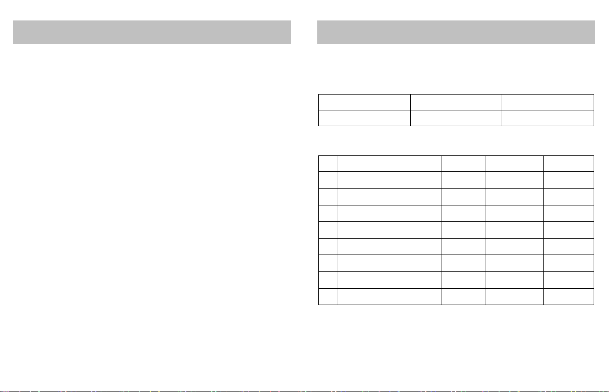
Voltage measurement and simulation:
Function Range Resolution Accuracy ± (% of reading +
Counts)
DC V / mV INPUT
Auto range 0 ~ 110 mV 0.01 mV ± (0.05 % + 5 counts)
0 ~ 15 V 0.001V ± (0.05 % + 5 counts)
DC V / mV
OUTPUT
0 ~ 100 mV 0.01 mV ± (0.05 % + 5 counts)
0 ~ 15 V 0.001V ± (0.05 % + 5 counts)
Input impedance: 2 M Ω(nominal) < 100 pF
Over voltage protection: 30 V
Voltage driver capability: 1 mA
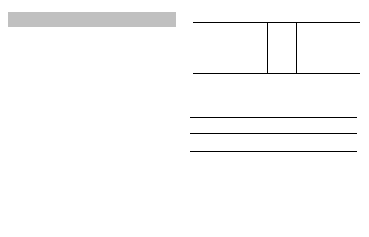
DC mA measurement and simulation
Range Resolution Accuracy @ 25 °C
± (% of reading + Counts)
0 ~ 24 mA
(Inputand Output) 0.001 mA ± 0.03% + 5
Overloadprotection: 125 mA, 250 V fast acting fuse
Percent display: 0 % = 4 mA, 100 % = 20 mA
Sourcemode: compliance 1000 Ω at 20 mA for battery voltage ≥ 6.8 V (700 Ω
at 20 mA for battery voltage5.8 to 6.8 V )
Simulatemode: Externalloopvoltagerequirement:24V nominal,30 Vmax, 12Vmin
Loop Power
Internal power supply 24 V ± 10 % / 25 mA max.

9
5.1. MODEL DC80L GENERAL SPECIFICATIONS
Maximum voltage allowed between any terminal and earth ground or between the
two input terminals: ............................................................................................30 V
Storage temperature:........................................................................-40 °C ~ 60 °C
Operating temperature:.....................................................................-10 °C ~ 55 °C
Operating altitude:.................................................................3000 meters maximum
Temperature coefficient:....................................................................± 0.005 % / °C
(for the temperature range -10 °C to 18 °C and 28 °C to 55 °C)
Relative humidity:...........................................................................95 % up to 30 °C
........................................................................................................75 % up to 40 °C
........................................................................................................45 % up to 50 °C
........................................................................................................35 % up to 55 °C
Shock:...........................................................................Random 2 g, 5 Hz to 500 Hz
Safety:............................................................................................1 meter drop test
Power requirement:......................................................................................6 x AAA
Size:.............................................................. 204 mm (L) x 99 mm (W) x 46 mm (H)
Weight:.............................................................................460 g (including batteries)
External power supply.......................................................................9 Vdc / 500 mA
5.2. MODEL DC80L FRONT PANEL
The keypad and display functions are shown below:
Loop power24 V to ground
mA measurement input jack
Input or output negative (GND)
jack
V / mV input or output jack
Power ON / OFF switch
V / mV mode key
mA / mA %mode key
INPUT/OUTPUTselection key
Fast increment key
Fast decrement key
Increment key
Decrement key
Low battery indication
INPUT mode indication
OUTPUT mode indication
Result value
V / mV indication
mA / mA % indication

10
5.3. PROTECTION
The MODEL DC80L calibrator uses two protection fuses, rated 125 mA / 250 V,
internally connected in series with the current terminals (2) and (4).
To avoid personal injury or damage to the calibrator, use only 125 mA / 250 V fast
fuses.
Notes on fuses:
-Fuse 1 is probably blown out when the display flashes the message OL while
in Voltage output mode with the leads removed from the calibrator.
-Fuse 2 is probably blown out if the calibrator reads 0.000 in mA input mode,
even under the presence of a current input signal
5.4. MODEL DC80L OPERATING INSTRUCTIONS
DC mV and V measurements
1. Press the power switch to
turn on the Calibrator.
2. Press the INPUT / OUTPUT
mode key to select INPUT
mode.
3. Press the V/mV mode key
to select mV input .
4. Plug the red test lead to “V” jack
and the black one to the
“COM” jack .
5.
Connect the test leads
according to the signal polarity:
red to thepositive polarity, black
to thenegative polarity(GND).
6. Measurement value is shown on
the display .

11
DC mV and V generation
1. Press the power switch to
turn on the Calibrator.
2. Press the INPUT / OUTPUT
mode key
to select
OUTPUT mode .
3. Press the V / mV mode key
to select the desired output
scale. The mode indication (V or
mV) is shown in .
4. Use the increment / decrement
keys to adjust
the output to the desired value.
5. Plug the red test lead in the “V”
jack and the black one to
the COM jack .
6. C
onnect the positive test lead
(red) and the negative test lead
(black) to the target equipment.
7. For changing the output value,
use the increment / decrement
keys and the V
/ mV mode key until the
desired value is displayed.
DC mA measurement
a) Using external power supply
1. Press the power switch to turn
on the Calibrator.
2. Press the INPUT / OUTPUT
selection key to select input
mode. The INPUT sign is shown
on the display .
3. Press the mA / mA % mode key
, to select mA or mA % .
4. Plug the red test lead in the mA
jack and the black one to
the COM jack .
5. Connect the test lead according
to the signal polarity (red to the
positive, black to the negative).
6. The measurement is shown on
the display .

12
b)Measurements using calibrator’s internal power supply for powering the
loop
The calibrator provides an internal 24 V power supply for measuring the signal of
2-wire transmitters (sink transmitters). The 24 Vdc is applied between terminals
+LOOP e COM. The sink transmitter is to be connected between terminals
+LOOP (Power supply output) and mA (terminal for the loop current monitoring).
1. Press the power switch to
turn on the Calibrator.
2. Choose OUTPUT mode by
pressing the INPUT / OUTPUT
key .
3. Press the mA / mA % mode key
to choose the desired unit.
The sings mA or mA % will
be presented on the display.
4. Plug the red test lead into the
LOOP jack and the black
one to the mA jack .
5. Connect the test leads such that
the current enters the red lead
and returns to the power supply
through theblack lead.
6. The measurement is shown on
the display .
DC mA generation
a) Sourcing mA
1. Press the power switch to
turn the CalibratorON.
2. Press the input / output mode
key
to select OUTPUT
mode .
3. Press the mA / mA % mode key
to select mA or mA % .
4. Press the increment /
decrement keys
to set the desired output value.
5. Plug the red test lead into the
LOOP jack and the black
one to the Vjack .
6. Connect the test leads such that
the current enters the red lead
and returns to the power supply
through theblack lead.
7.
To change the output value,
press the increment / decrement
keys and / or
the mA mA % mode key .

13
b)Simulating a 2-wireTransmitter (sink transmitter)
1. Press the power switch to
turn on the Calibrator.
2. Press the INPUT / OUTPUT
mode key
to select
OUTPUT mode .
3. Press the mA / mA % mode key
to select mA or mA % .
4. Press the increment /
decrement keys
to set the desired output value.
5. Plug the red test lead into the V
jack and the black one to
the COM jack .
6. Connect the test leads such that
the current enters the red lead
and returns to the power supply
through theblack lead.
7. T
o change the output value,
pressthe increment/ decrement
keys and / or
the mA / mA % mode key .
Accessories: a pair of Test Leads
6.MAINTENANCE
Cleaning
Periodically wipe the case with a damp cloth and detergent; do not use abrasives
or solvents.
Calibration
Calibrate your calibrator once a year to ensure its performance according to the
specifications.
Replacing the Battery
Change the battery when the display signs .
Turn off the power, unscrew the battery cover, and replace the batteries.
Distributed By:
Temperature & Process Instruments, Inc.
1767 Central Park Ave.
Suite 112
Yonkers, NY 10703
Phone: 914-673-0333
Web Site: www.tnp-instruments.com
This manual suits for next models
2
Table of contents