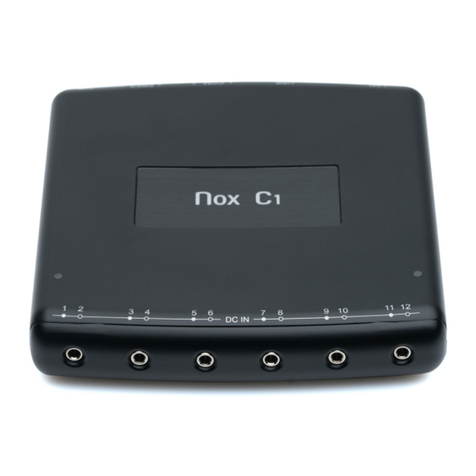
Nox Medical Nox C1 User manual

MANUAL
Copyright 2016 Nox Medical

Nox C1 Manual
Version 1.4
Latest Revision: May 2016
Copyright © 2016
Nox Medical - All rights reserved
Manufactured by:
Nox Medical ehf
Katrinartuni 2
IS - 105 Reykjavik
Iceland
Website: www.noxmedical.com
For distributor information go to:
www.noxmedical.com
Copyright Notice
No part of this publication may be reproduced, transmitted, transcribed, stored in a
retrieval system, or translated into any language or computer language, in any form,
or by any means: electronic, mechanical, magnetic, optical, chemical, manual, or
otherwise, without the prior written authorization from Nox Medical.
Disclaimer
This document may contain typographical errors or technical inaccuracies. Nox
Medical does not accept any liability for the use or misuse whether direct or indirect
of the products, or for damages arising out of the use of or inability to use the
products. Users must accept all responsibility for any results obtained by or concluded
from data obtained by the products including software from Nox Medical. All clinical
conclusions and decisions that are based on the use of this product are the
responsibility of the user.
License Notice
The Nox C1 device uses software components covered by open source licenses.
Licenses covering these software components are available on the Nox Medical
website:
www.noxmedical.com/products/nox-c1

Nox C1 Manual
~ 3 ~
Table of Contents
Table of Contents ....................................................................................................... 3
Introduction................................................................................................................ 5
Scope ..................................................................................................................... 5
Warnings and Cautions for Use ............................................................................. 5
Device Description...................................................................................................... 8
Intended Use.......................................................................................................... 8
Contraindications................................................................................................... 9
Nox C1 Interface .................................................................................................. 10
Device Inputs/Sensors .............................................................................................. 12
Connect to DC Power........................................................................................... 13
Device Status ....................................................................................................... 15
Analog Inputs ....................................................................................................... 16
Differential Pressure Sensor ................................................................................ 17
Serial Inputs ......................................................................................................... 18
Serial-over-USB Inputs ......................................................................................... 18
Ambient Light Sensor........................................................................................... 19
Network Configuration ............................................................................................. 20
Default Factory Configuration ............................................................................. 20
Factory Reset ....................................................................................................... 20
Setup Nox C1 Access Point with the Nox A1 System................................................ 21
System Network Overview .................................................................................. 21
Maintenance............................................................................................................. 24
Compatible Sensors and Devices.............................................................................. 26
Specifications............................................................................................................ 27
Nox C1 Device ...................................................................................................... 27
Regulatory Information ............................................................................................ 29

Nox C1 Manual
~ 4 ~
Performance Testing and Validation Summary ................................................... 29
Classification ........................................................................................................ 29
Description of Symbols and Abbreviations.......................................................... 29
Bluetooth® Wireless Technology ......................................................................... 31
EMC Information.................................................................................................. 31
About........................................................................................................................ 40

Nox C1 Manual
~ 5 ~
Introduction
Congratulations on choosing the Nox C1 access point. The Nox C1 is a
Bluetooth® access point that enables measurement, receiving and streaming
of physiological signals during sleep. The Nox C1 is intended to be used with
the Nox A1 system to enable online functionality of the system.
Scope
This manual covers the instructions for the Nox C1 access point, and how to
setup and operate the device. This manual does not cover the software
application needed for the device configuration.
Warnings and Cautions for Use
Warning: The C1 device is NOT certified for continuous monitoring
where failure to operate can cause injuries or death of the patient.
Caution: U.S. federal law restricts the C1 device to sale by, or on the
order of, a licensed medical practitioner.
Caution: The C1 device complies with the international standard IEC
60601-1-2 for electromagnetic compatibility for medical electrical
equipment and/or systems. That standard is designed to provide
reasonable protection against harmful interference in a typical
medical installation. However, because of the proliferation of radio-
frequency transmitting equipment and other sources of electrical
noise in healthcare and other environments, it is possible that high
levels of interference due to close proximity or strength of source
might disrupt the performance of the device. Medical electrical
equipment needs special precautions regarding EMC, and needs to be
installed and put into service according to the EMC information
provided in the “EMC Information”section of this manual.
Warning: Electromagnetic interference (EMI) can be picked up by the
analog channels of the C1 device, causing disturbed or altered signals
to appear in the PC software. This may affect data analysis and result
in possible incorrect treatment.
Warning: The use of accessories, transducers, sensors, and cables
other than those listed in this manual may result in increased
emissions and/or decreased immunity of this device.
Warning: The C1 device should not be used adjacent to or stacked
with other equipment. If adjacent or stacked use is necessary, the C1
device should be observed to verify normal operation in the
configuration in which it will be used.
Warning: The C1 device may be interfered with by other equipment,
even if that equipment complies with CISPR emission requirements.
Warning: The C1 device is not designed to give a specified degree of
protection against harmful ingress of liquids. Do not autoclave or
immerse the device in any kind of liquids. Ingress of liquids may result

Nox C1 Manual
~ 6 ~
in electric shock.
Warning: Only use United States Environmental Protection Agency
(EPA) registered products for cleaning/disinfection of the C1 device.
Warning: Do not use damaged equipment, sensors or accessories.
This may result in bad performance of the device or patient/operator
injury.
Warning: There are no user serviceable parts inside the C1 device.
The C1 device should be serviced by authorized parties only. Service
performed by non-authorized parties may affect data analysis and
result in possible incorrect treatment. The warranty is void if the C1
device is opened.
Warning: No modification of the C1 device is allowed. Un-authorized
modifications may affect data analysis and result in possible incorrect
treatment.
Warning: External equipment and all auxiliary devices intended for
connection to signal input, signal output or other connectors shall
comply with the relevant product safety standards, e.g. IEC 60950-1
for IT equipment and the IEC 60601 series for medical electrical
equipment, to prevent electric shocks. In addition, all such
combinations –systems –shall comply with the safety requirements
stated in the general standard IEC 60601-1, edition 3/3.1, clause 16.
Any equipment not complying with the leakage current requirements
in IEC 60601-1 shall be kept outside the patient environment, i.e. at
least 1.5 m from the patient support. Any person who connects
external equipment to signal input, signal output or other connectors
has formed a system and is therefore responsible for the system to
comply with the requirements. If in doubt, contact a qualified medical
technician or your local representative.
Caution: After connecting a new auxiliary signal to the C1 connectors
OR after modifying the connection of the auxiliary signals OR after
changing the mode of the auxiliary devices signal output, always
verify the correct setup by performing an actual recording, making
the auxiliary device create a known signal, and monitoring the
appearance and values measured in the recording software, in order
to prevent signals that would lead to incorrect interpretation and
possible incorrect treatment.
Warning: All the auxiliary devices connected to the C1 device should
be powered from a single power strip to ensure a common ground,
avoid ground potential difference skewing or disturbing the signals
and thus prevent possible incorrect treatment.
Warning: The C1 device may not be used for direct patient
connections where failure to operate can cause injuries or death of
the patient.
Warning: Only use power supply FRIWO MP115 Medical-7555M/12
with the C1 device. The use of an incorrect power supply may result
in electric shock or cause the device to overheat, which may result in
patient/operator harm.

Nox C1 Manual
~ 7 ~
Warning: The USB channels, serial channels and analog channels are
signal input/output (SIP/SOP) auxiliary ports not to be connected in
direct galvanic connection to the patient. This may result in electric
shock.
Please read the user instructions carefully before initial use,
especially sections marked with an exclamation mark.

Nox C1 Manual
~ 8 ~
Device Description
The Nox C1 access point is a Bluetooth® access point that enables
measurement, receiving and streaming of physiological signals during sleep.
The Nox C1 access point communicates with the Nox A1 recorder over
Bluetooth® and with the Noxturnal PC software over Ethernet to allow
configuration of the recorder and streaming of data. The Nox C1 is able to
measure signals from various auxiliary devices and has a built-in ambient light
sensor and a differential pressure sensor. The Nox C1 offers system extension
for the Nox A1 system with the integration of various auxiliary devices.
The Nox C1 channels and built-in capabilities include the following:
12 analog channels; for recording of DC signals from auxiliary devices
2 USB channels; to support devices connected via USB
2 serial channels; for recording of serial signals from auxiliary devices
2 pressure sensor channels; for recording of differential pressure for
pneumoflow recordings
1 built-in ambient light sensor
1 built-in Bluetooth® module; to support wireless connectivity
allowing the device to record signals from the Nox A1 recorder
The Nox C1 is also equipped with an Ethernet input; to support connection of
the device to an Ethernet network for streaming of data and commands
between the device and a remote computer.
The Nox C1 access point is powered by a medical grade power supply
providing medical grade isolation from mains.
Intended Use
The Nox C1 access point is intended for measuring, receiving and streaming
of physiological signals during sleep. The Nox C1 access point communicates
with Nox recorders over Bluetooth® and with the Noxturnal PC software over
Ethernet to allow configuration of the recorders and streaming of data. The
Nox C1 access point receives Bluetooth® data stream from Nox recorders, has
input ports for measuring of signals originating from various auxiliary devices,
and has internal sensors for ambient light measurement and
pneumotachography. The measured/received signals are processed within
the Nox C1 access point before they are streamed forward to the Noxturnal
software.
The Nox C1 access point is intended for patients older than two years of age.
The intended environments are professional healthcare facilities, including
hospitals, sleep centers and sleep clinics.
The Nox C1 Access Point is intended to be set-up by professionals (healthcare
professionals and service personnel) with relevant qualifications and skills.

Nox C1 Manual
~ 9 ~
Contraindications
The Nox C1 access point is NOT intended for any continuous patient
monitoring or automatic diagnosis.

Nox C1 Manual
~ 10 ~
Nox C1 Interface
The Nox C1 access point interface consists of an indicator light (LED) for
device status, ambient light sensor, analog channel inputs, Ethernet cable
input, factory reset button, USB input, serial inputs, differential pressure
sensor inputs and power supply connector. See the figures and tables below
for detailed description.
Device Inputs and Sensors
The figure below shows the top view of the Nox C1, showing the device’s
status LED (1) and the ambient light sensor (2). For device status indicated
with the LED, refer to the “Device Status” section.
The figure on the next page shows the front view of the Nox C1, showing the
six analog inputs, labelled DC IN 1-12.
2
1

Nox C1 Manual
~ 11 ~
The figure below shows the rear of the Nox C1, showing the six inputs
available. Refer to the table below for input definition.
The following table lists the Nox C1 access point inputs and the
corresponding input labeling.
NUMBER
FUNCTION
INPUT/SENSOR LABEL
1
Indicator light for device status
No label on device
2
Ambient light sensor
No label on device
3
Analog inputs
DC IN 1-12
4
Ethernet cable input
LAN
5
Factory reset button
No label on device
6
USB inputs
USB
7
Serial inputs
1 COM 2
8
Differential pressure sensor
inputs
+ PRES -
9
DC power supply connector
9
8
7
6
5
4

Nox C1 Manual
~ 12 ~
Device Inputs/Sensors
The Nox C1 device is operated by the Noxturnal PC software. For instructions
on how to configure and operate the device from the Noxturnal software
refer to the Noxturnal manual. The Noxturnal software and detailed user
instructions are provided in electronic form at: support.noxmedical.com.
Warning: Do not use damaged equipment, sensors or
accessories. This may result in bad performance of the device
or patient/operator injury.
Warning: The C1 device is NOT certified for continuous
monitoring where failure to operate can cause injuries or
death of the patient.
Warning: External equipment and all auxiliary devices
intended for connection to signal input, signal output or other
connectors shall comply with the relevant product safety
standards, e.g. IEC 60950-1 for IT equipment and the IEC
60601 series for medical electrical equipment, to prevent
electric shocks. In addition, all such combinations –systems –
shall comply with the safety requirements stated in the
general standard IEC 60601-1, edition 3/3.1, clause 16. Any
equipment not complying with the leakage current
requirements in IEC 60601-1 shall be kept outside the patient
environment i.e. at least 1.5 m from the patient support. Any
person who connects external equipment to signal input,
signal output or other connectors has formed a system and is
therefore responsible for the system to comply with the
requirements. If in doubt, contact a qualified medical
technician or your local representative.
Caution: After connecting a new auxiliary signal to the C1
connectors OR after modifying the connection of the auxiliary
signals OR after changing the mode of the auxiliary devices
signal output, always verify the correct setup by performing
an actual recording, making the auxiliary device create a
known signal, and monitoring the appearance and values
measured in the recording software, in order to prevent
signals that would lead to incorrect interpretation and
possible incorrect treatment.
Warning: All the auxiliary devices connected to the C1 device
should be powered from a single power strip to ensure a
common ground, avoid ground potential difference skewing
or disturbing the signals and thus prevent possible incorrect
treatment.
Warning: The C1 device may not be used for direct patient
connections where failure to operate can cause injuries or
death of the patient.

Nox C1 Manual
~ 13 ~
Connect to DC Power
Warning: Only use power supply FRIWO MP115 Medical-
7555M/12with the C1 device. The use of an incorrect power
supply may result in electric shock or cause the device to
overheat, which may result in patient/operator harm.
The Nox C1 is powered by FRIWO MP115 Medical-7555M/12, a specific
medical grade power supply rated with operating voltage of 12 volts and
providing medical grade isolation from mains. Connect the power supply into
the DC power connector on the rear of the device and have the applicable
regional adapter connected to the power supply.
Verify that the LED indicator light on top of the Nox C1 device starts blinking
amber immediately after connection of the power supply and starts blinking
green when the startup sequence of the device is completed and the Nox C1
is available for configuration.
FRIWO MP115 Medical-7555M/12 (FW7555M/12)
The medical grade power supply FRIWO MP115 Medical-7555M/12 is the
only power supply that should be used with the Nox C1 to ensure safety and
device operation. For user instructions, product specifications and regulatory
information please refer to the product website: www.friwo-
shop.de/en/power-supplies/medical-power-supplies/169/mpp15-
medical?c=8970.
NOTE: Please read user instructions before use. Always
observe these instructions.
NOTE: The LED is the operating indicator.
Caution: In the case of visible damages on the housing or on
the cord do not use the power supply.
Warning: The device should never be operated or even stored
at places listed below, because this could lead to operating

Nox C1 Manual
~ 14 ~
failures:
oPlaces, which are heavily exposed to moisture
or where water condensing may occur
oPlaces, which are exposed to special
environmental conditions
oPlaces, which are subject to constant vibrations
oPlaces, which are subject to high temperature
fluctuations
oOutdoors
Caution: Always disconnect the power supply from mains
during lighting storms or when not in use.
Caution: The power supply itself is the disconnect device.
Never use the cord to pull the power supply from the mains.
Warning: The power supply is maintenance free. It must not
be opened. (Risk of electrical shock).
NOTE: A modification of the power supply is not allowed (Loss
of warranty).
Warning: The device may only be repaired by authorized
personnel.
Warning: Remove from mains before cleaning. Do not clean
with detergents. Clean only with a dry cloth.
NOTE: The power supply unit is intended for supplying end
medical product by its output voltage.
Warning: The unit shall not be used for use in an oxygen rich
environment.
Warning: The unit it is not intended to be used with
flammable anesthetics and not intended for use in
conjunction with flammable agents.

Nox C1 Manual
~ 15 ~
Device Status
The Nox C1 has a built-in LED for device status indication. The LED is located
on the top panel of the device. Refer to the table below for a description of
the different states of the Nox C1 indicated with the LED.
Status Light Description
Off
Nox C1 is not connected to power and is turned
off
Blinking amber
Nox C1 is connected to power and is completing
the startup sequence
Blinking green
Nox C1 is connected to power and turned on
A recording is not running
Solid green
A recording is running
Solid amber
Firmware error indication, device is not
functional
Alternating green
and amber
Device should be factory reset (refer to section
“Factory Reset”)
Firmware upgrade/factory reset is running
Do not unplug the power source
The LED brightness will automatically dim during a recording to ensure
patient comfort.

Nox C1 Manual
~ 16 ~
Analog Inputs
Warning: The analog channels are signal input/output
(SIP/SOP) auxiliary ports not to be connected in direct
galvanic connection to the patient. This could result in electric
shock.
The Nox C1 device is equipped with 12 analog channels suitable for collecting
of DC signals from auxiliary devices. The channels are collected on 6 inputs,
labeled DC IN from 1 to 12 on the top of the device. Each analog input yields
2 channels. Auxiliary devices can be connected to the Nox C1 analog inputs
using standard 3.5 mm phono stereo connectors/3.5 mm mono phono
connectors/3.5 mm stereo to dual mono adapters. The voltage range allows
interfacing signals from -5 V to +5 V.
The 12 analog channels offered by the Nox C1 have six inputs labeled DC IN
from 1 to 12, see the figure above. The table below addresses the channel
identification.
Analog Inputs
Analog Channels 1-12
Analog Input 1 and 2
Channel 1
Channel 2
Analog Input 3 and 4
Channel 3
Channel 4
Analog Input 5 and 6
Channel 5
Channel 6
Analog Input 7 and 8
Channel 7
Channel 8
Analog Input 9 and 10
Channel 9
Channel 10
Analog Input 11 and 12
Channel 11
Channel 12

Nox C1 Manual
~ 17 ~
The table below lists connectors that can be used for connection to the Nox
C1 analog channel inputs.
Connector Type
Channel Identification
3,5 mm stereo
phono connector
A stereo connector is able to
carry two analog channels
(e.g. channels 1 and 2)
3,5 mm mono
phono connector
A mono connector is able to
carry one analog channel (e.g.
channel 1)
3,5 mm stereo to
dual mono
adapter
White connector is for odd
number channels (e.g.
channels 1, 3, 5 etc.)
Red connector is for even
number channels (e.g.
channels 2, 4, 6 etc.)
Please refer to the Noxturnal software user manual for more information on
how to configure the analog channels.
Differential Pressure Sensor
To setup the Nox C1 for a pneumoflow recording, connect two Nox filter tube
connectors to the differential pressure sensor inputs on the rear of the
device, labelled + PRES -. The differential pressure sensor inputs are designed
to fit directly with the filter tube connector interface from Nox Medical. The
figure below shows the Nox filter tube connectors connected to the
differential pressure sensor inputs.
Channel 1
Channel 2
Ground
Channel 1
Ground

Nox C1 Manual
~ 18 ~
Serial Inputs
Warning: The serial channels are signal input/output
(SIP/SOP) auxiliary ports not to be connected in direct
galvanic connection to the patient. This could result in electric
shock.
To record signals from auxiliary devices over a serial connection connect a
3.5 mm stereo phono connector carrying the serial signal to the serial input
on the rear of the device. The figure below shows the rear of the device,
where the serial inputs are located. The serial inputs are labelled 1COM 2.
Serial-over-USB Inputs
Warning: The USB channels are signal input/output (SIP/SOP)
auxiliary ports not to be connected in direct galvanic
connection to the patient. This could result in electric shock.
The device supports serial-over-USB dongles, allowing the user to connect
more than two serial auxiliary devices simultaneously. The USB inputs are on
the rear of the device. The figure below shows the rear of the device, where
the USB inputs are located. The USB inputs are labelled USB.

Nox C1 Manual
~ 19 ~
Ambient Light Sensor
The Nox C1 has a built-in ambient light sensor located on the top panel of the
device; see the figure below (1).
The light sensor can be used for light detection in the patient room. For the
light sensor to work properly make sure not to cover the Nox C1 light sensor.
For the light sensor specifications refer to the “Specifications” section.
1

Nox C1 Manual
~ 20 ~
Network Configuration
Default Factory Configuration
The factory state of the Nox C1 is listed in the table below.
Nox C1 Network
Configuration
Details
DHCP server
DHCP pool: 192.168.101.64 - 192.168.135.128
Static IP address
192.168.101.10
Universal Plug and Play (UPnP)
discovery
Networking protocol that permits the Nox C1 to
be discovered on a network
The Nox C1 network configuration can be managed through the Noxturnal
software. Please refer to the Noxturnal manual for instructions on how to
configure the Nox C1 network settings.
Factory Reset
To reset the Nox C1 to factory state follow the instructions below:
1. Unplug the power supply from the Nox C1 device
2. Reset the device by performing the following:
i. Use a sharp pin (such as a toothpick) and press and hold the
reset button on the rear of the device (see figure below)
ii. While pressing the reset button connect the power supply
to the device
iii. You can release the reset button once you see the device
LED alternating between green and amber
3. The LED on the top panel will blink amber while the device is
completing the startup sequence
4. After approximately 60 seconds the LED starts blinking green. This
indicates that the device has been reset to factory defaults and will
have the network configuration listed in the “Default Factory
Configuration” section
NOTE: Do not use a metallic item to perform the factory reset.
Other manuals for Nox C1
1
Table of contents
Other Nox Medical Wireless Access Point manuals
Popular Wireless Access Point manuals by other brands

D-Link
D-Link xtreme n duo dap-1522 Quick installation guide

NETGEAR
NETGEAR WG302v2 - ProSafe 802.11g Wireless Access... Reference manual

peplink
peplink Surf 200BG-AP user guide

Airspan
Airspan AirSpeed 2900 installation guide

Quantum Networks
Quantum Networks QN-I-200 user guide

MRV Communications
MRV Communications MRW55 user guide