8National Rejectors, Inc. GmbH, Buxtehude
GENERALINFORMATION
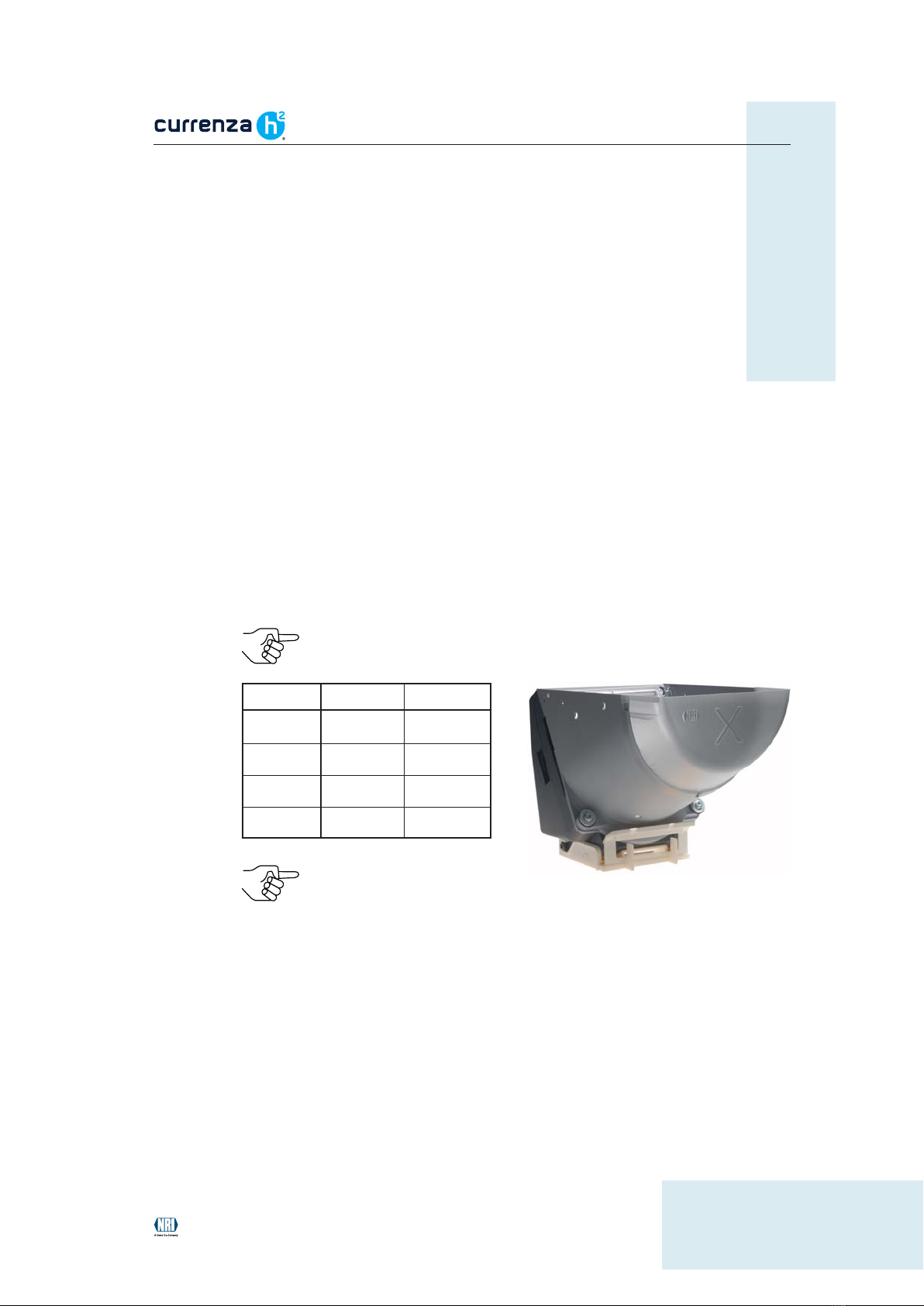
General information about the hopper currenza h2
The electromechanic hopper currenza h2is a coin payout system for
machines.Dependingonthemodelandthecointypeitcancollect2,000and
more coins, in order to be able to pay out these coins as change on
command of the machine control system. Due to its high capacity the
hopper is used in machines, that have to pay out certain coins as change
frequently, such as money changers, vending and amusement machines.
Thehopper modelsh2L andh2X areprojected andcannot be
deliveredyet.
The hopper is fitted with a machine interface, that can be configured for
parallelorserialccTalk operation accordingtorequirements.In thecaseof
the parallel interface the hopper communicates with the machine control
system using signal lines, whereas the ccTalk interface allows the hopper
to use the serial ccTalk data transfer protocol to communicate with the
control system as slave. The interface is configured according to customer
requirements on delivery.
The reliable and low-maintenance payout mechanism in the form of a
rotating disc driven by a motor is designed extra ruggedly, so that it
withstands innumerous coin payouts permanently.
Ifthehopperistobefilledautomatically,itcaninteractwithacoinvalidation
system without any problems (e.g. NRI coin validators G-13.mft, G-40 or
NRI coin changers c2, E-66/A-66, G-46).
The currenza h2features
• Models in various sizes for a coin capacity as high as possible
depending on the machine dimensions
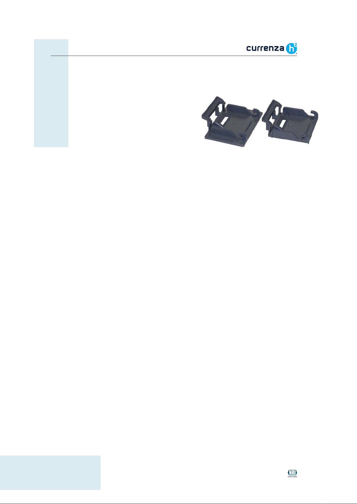
• Space-saving dual hopper installation thanks to coin passage
• switchable machine interface for parallel or serial ccTalk operation
• Suitable for paying out a lot of different coin types
• Payout speed of up to 7.5 coins per second
• Operating safety due to coin payout sensors, automatic error
detection and anti-jam function
• Optional empty and full recognition