NSK Varios 370 User manual
OPERATION MANUAL
Please read this Operation Manual carefully
before use, and file for future reference.
OM-E0506E 003
Multi Function Ultrasonic Scaler
Varios 370
Multi Function Ultrasonic Scaler
Varios 370
1
ENGLISH
Cautions for handling and operation
Read these cautions carefully and use only as intended or instructed.
Safety instructions are intended to avoid potential hazards that could result in personal injury or damage to the device.
Safety instructions are classified as follows in accordance with the seriousness of the risk.
WARNING
Classifications of equipment
• Type of protection against electric shock:
– Class II equipment
• Degree of protection against electric shock:
– Type BF applied part:
• Method of sterilization or disinfection recommended by the manufacture:
– See 11. Sterilization
• Degree of protection against ingress of water as detailed in the current edition of IEC 60529:
– Foot Control: IPX1 (Protected against vertically falling water drops)
• Degree of safety of application in the presence of a flammable anesthetic mixture with air or with oxygen or nitrous oxide:
– EQUIPMENT not suitable for use in the presence of a flammable anesthetic mixture with air or with oxygen or nitrous
oxide.
• Mode of operation:
– Continuous operation
Intended to Use
This product is intended only for dental clinic /dental office use. This device generates ultrasonic waves intended for use in
dental applications such as scaling, root canal treatment, periodontal and cavity preparation.
Class Degree of Risk
WARNING A hazard that could result in bodily injury or damage to the device if the safety instructions are not
followed.
CAUTION A hazard that could result in light or moderate bodily injury or damage to the device if the safety
instructions are not followed.
NOTICE General information needed to operate the device safely.
Original Operation Manual
· TO PREVENT ELECTRIC SHOCK Do not unplug the AC Adaptor with wet hands.
· TO PREVENT ELECTRIC SHOCK Be sure to prevent water on the Control Unit.
· TO PREVENT ELECTRIC SHOCK Do not touch the handpiece backend electrical connections.
· TO PREVENT ELECTRIC SHOCK Use an electrical outlet that is grounded.
· If you feel any abnormality such as vibration, heat generation, abnormal noise, etc., prior or during the use of the unit, stop
using it immediately.
· This product is Medical Electrical equipment Electromagetic compatable (EMC).As described in the accompanying
documentation.
· Portable and mobile RF communications equipment can affect Electrical Medical equipment. Do not use RF equipment in
close proximity to the product.
· When installing the product, provide space of approximately 10cm around the Control Unit for easy access to the inlet and
the AC Adaptor.
· USE ONLY NSK genuine Tips when using NSK Varios Ultrasonic Scaler (Varios 370 or Varios 370 Lux)problems such as
damage, failure and accident of Handpieces resulting from use of Non-NSK Tips are not included in the warranty. The
following are the possible failure that could happen when using the Non-NSK Tips;
· Vibration failure caused by using non conforming screws.
· Patients accidental ingestion of broken Tips.
· Damage of thread ridge of handpiece.

2
· You must use the Tip within the power range described on the Tip-Power Guide. If you use it out of the power range, the
Tip might break or damage an operative site.
· When operating the product always consider the safety of the patient.
· Use by medical professional, such as doctor or dental hygienist, is intended.
· Check the vibration outside the patient’s oral cavity before use. If any abnormalities are found, stop using immediately and
contact dealer.
· Do not drop, hit, or subject to excessive shock to the Control Unit/Handpiece.
· To prevent possible tooth plane damage and handpiece overheating, Always use with sufficient water.
· Do not sterilize by ultraviolet light. Handpiece could discolor.
· Sterilize the Tip, Handpiece,Tip Holder, Tip Cover S and Tip Wrench by autoclaving. Wipe the Control Unit,Tip Holder, Tip,
AC Adaptor, Foot Control, and Handpiece Cord including the cover.
· If chemical, solvent or antiseptic solution is deposited on this product, immediately wipe it away. Discoloration or
deformation may occur if left.
· Do not disassemble or alter the handpiece/Control Unit.
· Keep away from patients with cardiac pacemakers.
· Keep away from explosive substances and flammable materials. Do not use for patients anesthetized under laughter gas.
(Nitrous oxide)
· This product needs special precautions regarding EMC and needs to be installed and put into service according to the
EMC information.
· The use of ACCESSORIES, transducers and cables other than those specified, with the exception of transducers and
cables sold by the manufacturer of this product as replacement parts for internal components, may result in increased
EMISSIONS or decreased IMMUNITY of this product.
· This product should not be used adjacent to or stacked with other equipment and that if adjacent or stacked use is
necessary, this product should be observed to verify normal operation in the configuration in which it will be used.
· If any water drops remain on the handpiece or handpiece cord after autoclaving,
wipe them off. Staining may result if left.
· There is the judgment that applies this product to a patient in the user side.
· Grounding reliability can only be achieved when the equipment is connected to
an equipment receptacle marked "Hospital Only" or "Hospital Grade".
· Do not apply excessive power to the Tip. It may damage the teeth because of the
ultrasonic vibration.
· During operation, high frequency oscillations in the handpiece and handpiece cord may affect computer and LAN Noise
may be heard during operation near a radio receiver.
· Be sure to turn off the Power/Volume Knob after use. Remove the AC Adaptor and water inside of the Control Unit before
storage.
· Users are responsible for operational control, maintenance and inspection.
· Clean/sterilize the product immediately after using it. Then store it. Leaving it non-sterile might lead to failure.
· When you have not used the product for long time and use it again, check the operation before use.
· Eye damage may result if the LED is stared directly into, Do not look into or turn it to the eyes of the patient.
· When abnormalities are found with a Control Unit and /or an AC adaptor, pull the AC adaptor from AC Outlet immediately.
· This product does not consider patient’s age (except infants), gender, weight or nationality.
· No special training is required for this device.
· Applied parts for patient and/or operator are/is Tip and Handpiece.
· Surface temperature of tip shall be more than 50 degree without using a tap water or bottle. To avoid this event, be sure to
use a tap water or bottle.
CAUTION
Power plug below is used
in North America area.
Plug Type NEMA 1-15P
(Hospital Grade Type)
English
3
* Operation Principle
A sinusoidal electrical signal, at ultrasonic frequency (f >20kHz ), is delivered by the generator. This signal is applied
to the ‘piezoelectric ceramic’ located inside the transducer. Piezoelectric ceramic converts this signal into mechanical
vibrations. These vibrations are at the same ultrasonic frequency as the electrical signal. The mechanical vibrations
are propagated towards the distal end of the transducer. The “TIP” insert, which is attached at the distal end of the
transducer, vibrates at ultrasonic frequencies and makes it possible to achieve the aimed purpose.
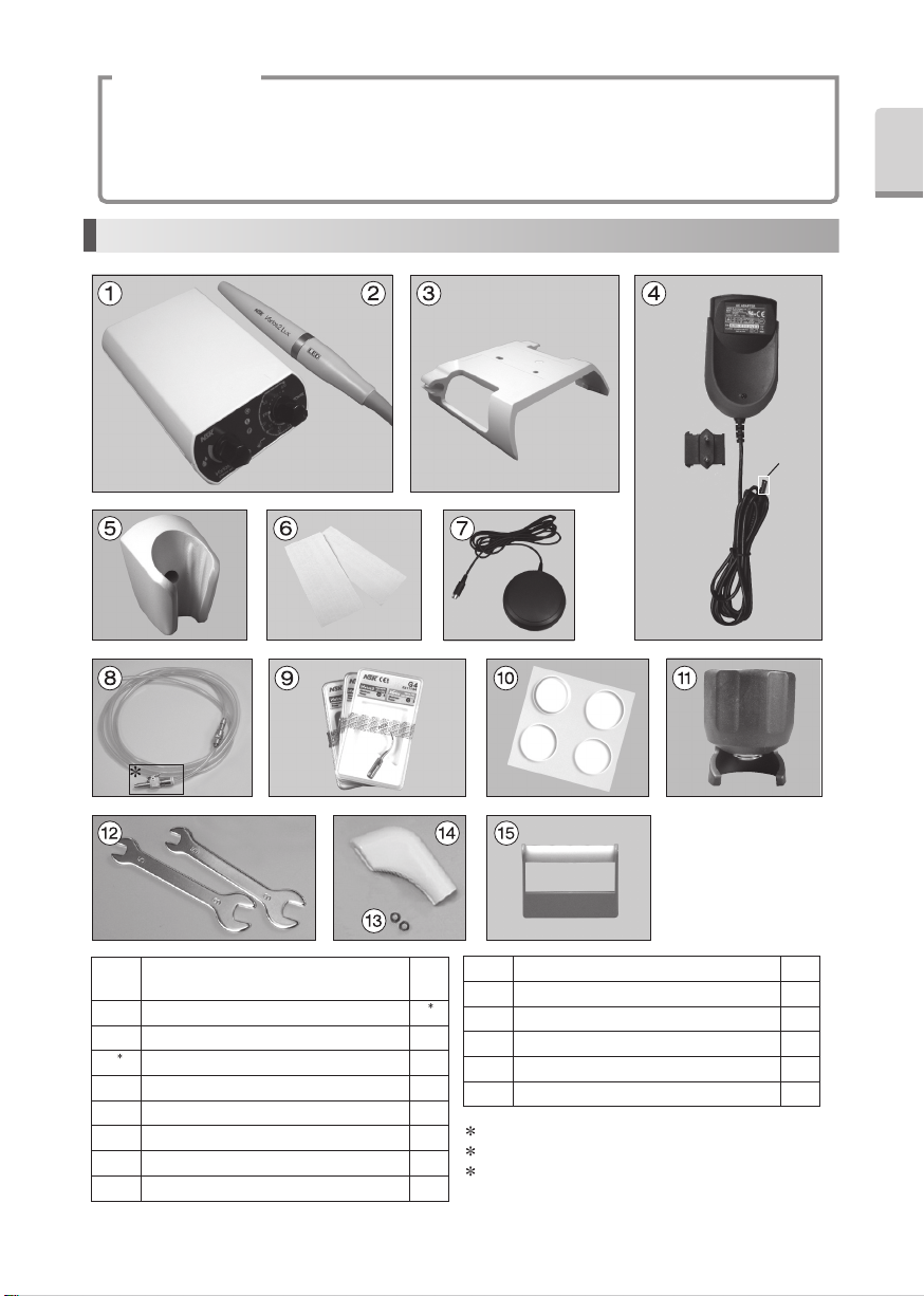
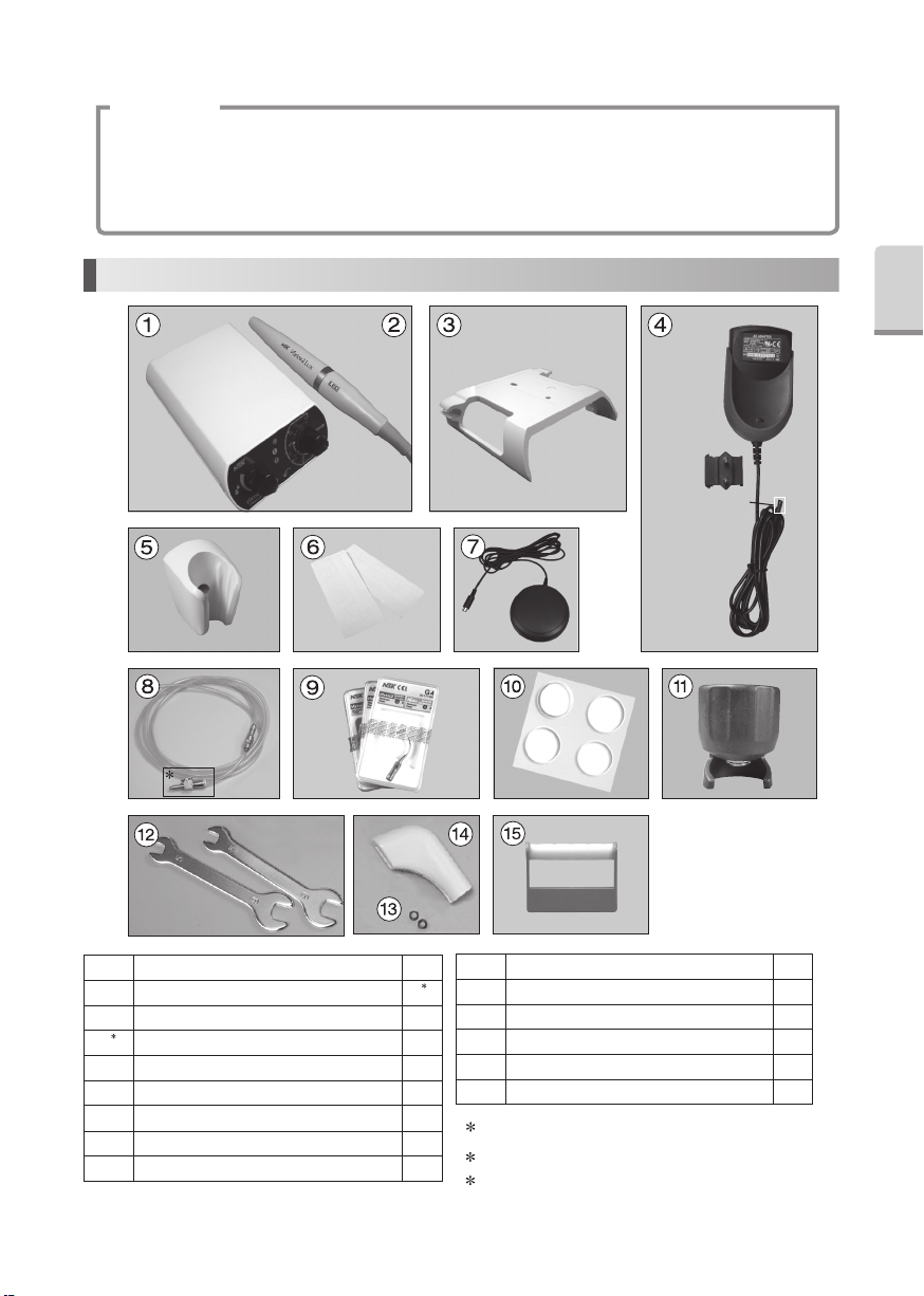
1. Component Names
1 By an area, AC Adaptor Shape change
2 Either one is contained with the set that you purchased
3 Only 120 V
1Control Unit
(with Handpiece Cord Unshielded 2M)1
2 Handpiece (Varios2 or Varios2 Lux) 1
2
3 Control Unit Holder 1
4
1AC Adaptor (Unshielded cord 5M)1
5 Handpiece Holder 1
6 Double-Face Tape 2
7 Foot Control (Unshielded 5M)1
8 Water Tube Set 1
9 Tip (G4, G6, G8)1
10 Rubber Pad 4
11 Tip Wrench 1
12 Spanner Wrench (5x8)2
13 O Ring 2
14 Tip Cover S (Option)-
15 Tip Holder (Option)-
DC Plug
3

4
2. Name and Function of each part
3. Prior to Operating System
Back side
Front side (Control Unit With Control Unit Holder)
Water Tube Connector
DC Connector
Foot Control Connector Handpiece Cord
Power Indicator
Power/Volume Knob
Control Unit Holder
Handpiece Cord Holder
Handpiece Cord Holder
Output Indicator
Water Volume Knob
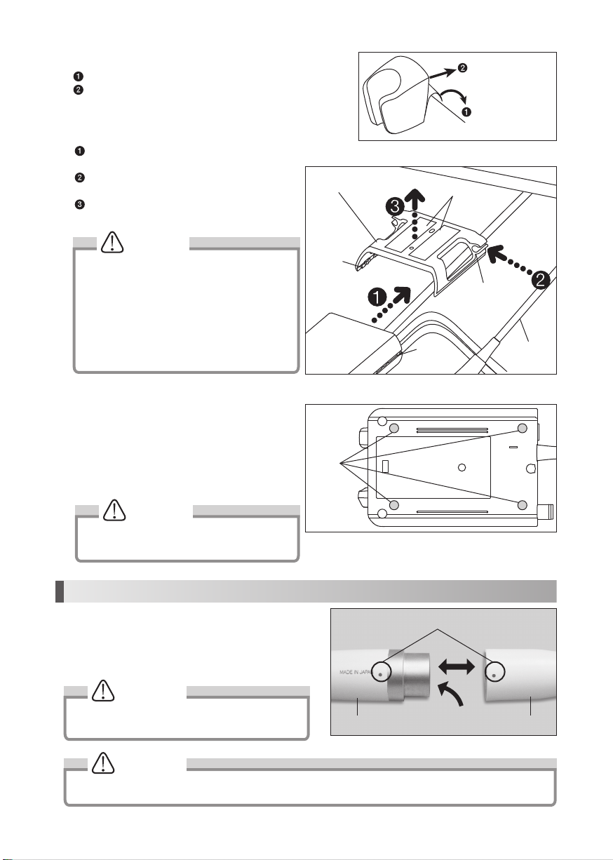
3-1 Set the AC Adaptor
Insert each plug into appropriate connector.
Set the AC Adaptor head like right Figure.
Slide into the Plug Head to the AC Adaptor.
To release, push the Release Button shown on the right
figure, and remove the Plug Head from the Adaptor
Body.
If abnormalities are found with the Control Unit and /
or the AC adaptor, remove the AC adaptor from the AC
Outlet immediately.
Plug Head
Adaptor Body
Release Button
This Holder can move back and forth.
English
5
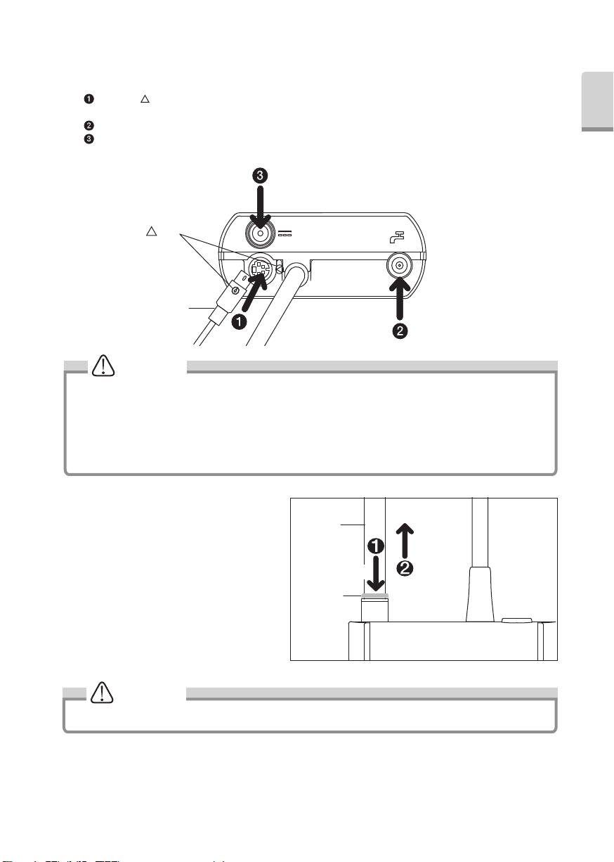
3-2 Connecting
Insert each plug into appropriate connector. (Fig.1)
Align the " " Mark on the Foot Control Connector and Foot Control Plug and connect those firmly into Foot Control
Connector.
Connect Water Tube (Non-Filter Side, refer to Fig.21 for detail)firmly into Water Tube Connector.
Connect AC Adaptor into DC Connector.
3-3 Disconnecting
3-3-1 DC Plug and Foot Control Plug
Simply pull out plugs from the Control Unit.
3-3-2 Water Tube (Fig.2)
Pull out the Water Tube while pushing the
White Ring.
CAUTION
· Insert plugs firmly into the connector. Lose connection may be cause a malfunction.
· Ensure Power is OFF on the Control Unit during the AC Adaptor Connection.
· Do not connect the cord in wall outlet before connecting DC Connector.
· Do not pull the AC Adaptor forcibly.
· Do not disconnect the AC Adaptor while pressing on the Foot Control.
· Turn OFF the power to connect or disconnect the cords and plugs.
White Ring
Fig.1
Fig.2
CAUTION
It requires the water removal before the Water tube disconnection.
PULL
Water Tube
PUSH
Mark
Foot Control Plug
6
WARNING
CAUTION
CAUTION
3-4 Handpiece Holder (Fig.3)
Peel off cover of the Double-Faced Tape.
Fix the Handpiece holder on the flat surface.
4. Mounting and Removing the Handpiece
Align the Dots on the Handpiece and the Handpiece Cord. Push
handpiece into connector.
To remove the handpiece, grip the Handpiece and plug of the
handpiece cord then pull it out stright. (Fig. 6)
To avoid Electrical Shock Do not touch the handpiece
backend electrical contacts.
CAUTION
· Do not pull the Handpiece cord forcibly. This is
because water tube had bended forcibly that is
inside the Handpiece cord. Water may not be
out appropriately from the handpiece.(Especially
for connection for Handpiece cord to Handpiece
cord Holder)
· You can mount Control Unit Holder on the Top
Surface and Bottom Surface.
Control Unit Holder is not mount to the bottom
when a Rubber Pad is attached to the bottom.
3-5 Handpiece Cord Holder and Control Unit
Holder (Fig.4)
Align the chase and Slide the Control Unit into
the Control Unit Holder.
Tuck the Handpiece Cord into Handpiece Cord
Holder.
Peel off the Double-Face Tape cover and put the
Control Unit Holder under the Table or Tray.
3-6 Rubber Pad
To stop slipping the Control Unit on the table, mount the
Rubber Pad at the bottom of it.
1) Clean bottom of the Control Unit.
2) Fit the Rubber Pad appropriate place as shown on
the Fig.5.
Handpiece
Cord Holder
Chaser
Control Unit Holder
Chaser
Double-Faced Tape
Dots
Handpiece backend
Handpiece Handpiece Cord
Fig.6
Always confirm that the handpiece is correctly seated and locked into place.
Fig.3
Fig.5
Handpiece
Cord
Fig.4
Rubber
Pad
To flat surface
Double-Faced Tape

English
7
Caution for Tip Usage
5. Mounting and Removing Tip
· Check the Tip before use. (Flush, Damage, Bending or Rust)
· Do not exceed Maximum Power Level for Tip. Damage to tooth structure and Tip may result.
· Do not hit metal or prosthetic crown etc. except for removing them. Tip could break and fall into mouth.
· Do not hit gingival, mucosa and/or skin directly. It could cause damage and/or burn injury.
· Do not sharpen and/or bend the Tip. Tip may damage and not generate enough vibration during scaling.
· During cutting, Tip will gradually wear away, as the Tip wears the stroke will get smaller and decrease cutting
efficiancy When level drops too far, change the Tip.(Tip Card check)
· DO ENSURE When securing tip to use the Tip Wrench as supplied, inefficient cutting will result.
· DO ENSURE before attaching Tip, Cleanliness of the tip screw, inefficient cutting will result.
· To avid personal injury DO ENSURE Tip is removed prior to disconnecting the handpiece or the handpiece cord.
· If you feel the Tip is not vibrating, remove it from an operative site, and press the Foot Control again. If this does
not improve the condition, Ensure the Tip is secure, turn the power off and restart it.
· When mounting the Tip, always use groves and Tip Wrench as supplied.
· Ensure that water volume must be “0”, when you use Tip which does not appear of water.
· Tip Wrench is consumable For reliable operation replace annually.
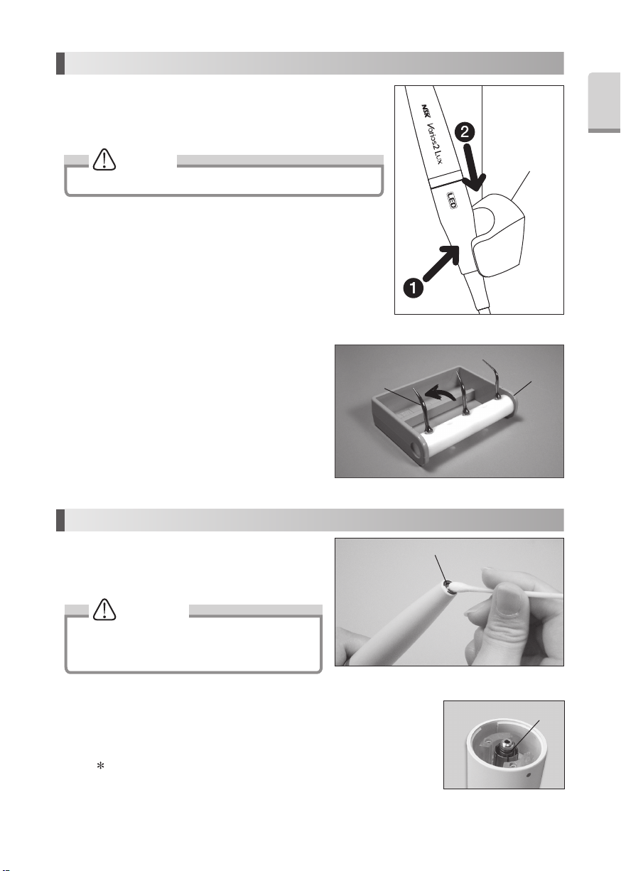
6. Operating Procedures
6-1 Power On (Fig.8)
Connect the AC Cord to the wall outlet. Rotate the Power/Volume Knob on the Control Unit. (Power indicator will light on.)
Fig.4
Loosen Tighten
Tip Wrench
Tighten
Loosen
Turn TIP lightly by hand, and install it.
Tip will insert from the bottom hole of Tip Wrench. Align the four corner of the Tip base area into the four corner of Tip
Wrench. And turn it clockwise until it clicks.
Do not touch the top part of TIP to avoid an injury. (SThere is the case that is longer than height of TIPWRENCH)
To remove the Tip, turn it counterclockwise with the Tip Wrench.
Fig.8
O N
O F F
Power
Indicator

8
NOTICE
· Turn the Power Volume Knob will increase or decrease the Power Level.
· If the Power Level is 0 (zero)and set the water volume, Tip will not oscillate but water comes out from the
handpiece.
6-3 Operate Varios 370 / 370 Lux
Tip vibration will begin when the Foot Control is depressed. Also, Output Indicator will be on. (For Varios2 Lux,
Handpiece LED will illuminate.)
NOTICE
6-5 Protection Circuit
It may overheat inside when you use this Control Unit in more than Power 8 at G for long time. In this case, Protection
Circuit reduces the Power automatically. (Power 7)
If you need to increase more than Power 7, decrease the power less than 5 once and increase again.
During Protection Circuit function, the Control Unit can not increase the Power Level more than 8.
6-2 Power Level Setting
DO ENSURE Power setting does not exceed the
recommended Power Level (Tip-Power Guide included
in the package.)
Set the power level with the Power/Volume Knob on
the Front Panel. Make sure the power level is set in the
appropriate range for the attached Tip.
6-4 After the Treatment
Release the Foot Control and Power off the Control Unit. Close the dental unit's water valve.
NOTICE
LED of the handpiece will remain ‘On’ for approx 5 seconds after Foot Control is released. (Varios2 Lux)
6-3-1 Water Supply Volume Adjustment
Turn the Water Adjustment Knob clockwise
gradually to increase the supply volume. (Fig. 10)
During the Handpiece operation :
Possible: Power Level and Water Volume adjustment.
Fig.10
Power Level for each mode
Fig.9
DecreaseIncrease

English
9
CAUTION
7. Provided Scaler Tips
The end of the Tip is thin and for supragingival fine scaling and interdental scaling. The
round cross-section allows tooth surfaces to be finished without causing damage.
Tip is article of consumption. We recommend periodical replacement. About time of replacement, check the Tip
Card.
G4
Apply the top of the Tip on the tooth plane and move it sideways
finely in the same way as G8 Tip. (Fig. 11)
Removal of supra and subgingival calculus. It provides easy access to interdental
spaces and narrow pockets.
G6
Insert the top of the Tip into the periodontal pocket and move it
slowly. The top of the Tip is sharp so that it could remove tartar
on long coroner and retracted gingival. (Fig. 12)
Clean periodontal pocket at low power. (Set the level less than
“Power 5” at P mode.)
Removal of supragingival and interdental calculus. This Tip can be used in all
quadrants and is very useful for the removal of hard calculus.
G8
Apply the top of the Tip on the tooth plane and move it sideways
finely along the neck of tooth. (Fig. 13)
Fig.11
Fig.12
Fig.13
10
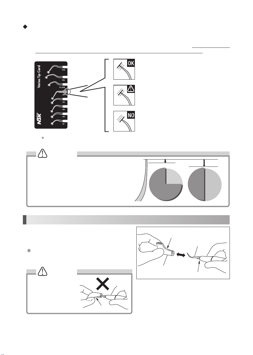
The Tip Card can be used to check the following tips : G1, G4, G6, G8, G9, P1/P1D, P10, and P20
Green: No wear - Tip is OK
Tip replacement is not necessary.
Red: Wear of 2mm - Tip is badly worn
Tip replacement is necessary.
Yellow: Wear of 1mm - Tip is showing some wear
Tip replacement is recommended.
CAUTION
CAUTION
Fig.15
8. How to Use Tip Cover S (Option)
Grip the Tip Cover S and insert it to the Tip.
To remove, grip the Tip Cover S and the handpiece & pull.
(Fig. 16)
The Tip Cover S is not designed for use as a Tip changing
tool.
Carefully insert the Tip
into the Tip Cover S. Avoid
injuring the fingers.
How to use the Tip Card
1) Place the neck of the Tip in the cut out.
2) Check wear of the Tip.
3) See the green, yellow and red line to check wear of the Tip. *See below what each color means. At NSK we recommend
to replace a Tip when the Tip meets the yellow line (wear of 1mm) to guarantee safe and effective use.
Tips are consumables. The efficiency of dental scaling
decreases approximately 25% when the top of the Tip
wears 1 mm and approximately 50% when it wears 2 mm.
In addition, the vibration condition changes owing to the
wear, which may damage a patient’s tooth surface. Check
the Tip wear condition with the Tip Card periodically, and
replace the Tip with a new one in good time.
Fig.16
Slit
1mm 2mm
25%
Decrease 50%
Decrease
Efficiency
Slit
Tip
Tip Cover
Tip-Handpiece Joint
Fig.14
English
11
CAUTION
9. Holder
10. Care and Maintenance
10-1 Cleaning of Optic Fiber (Varios2 Lux)
Wipe the debris off the end of the Optic Fibers at the
handpiece with alcohol soaked cotton swab. (Fig.19)
Do not use any sharp pointed tools to clean the Optic
Fiber End Face. In case the light degridation, contact
dealer.
10-2 Changing O-Ring
Handpiece Cord
An O-Ring is located in the Handpiece Cord Connector. Use a pointed tool to remove,
and mount new O-Ring into the groove. (Fig. 20)
Optional O-Ring: Order Code 0310020080
9-1 Handpiece Holder
While the Handpiece is not in use, put the Handpiece on the Handpiece
Holder. (Fig.17)
NOTICE
To prevent injury, always mount Scaler Tip Cover S.
Handpiece Holder
Fig.17
9-2 Tip Holder(Option)
For a Tip removed from the handpiece, use the Tip
Holder.
The Tip Holder is Autoclavable and hold up to 5 tips at
once. To Autoclave, tilt the tips in the direction of the
arrow in Fig.18.
Fig.19
Optic Fiber End Face
Tip Holder
Tip
Fig.18
Fig.20
O-Ring
12
CAUTION
· Do not sterilize by ultraviolet ray. The handpiece could discolor.
· If autoclaved with other instruments stained with chemical solution, it could strip the plating and make the surface
black.
· Do not autoclave any parts (the Control Unit, AC Adaptor, Foot Control, Handpiece Cord, O-Ring). Other than those
that can be subjected to autoclave sterilization. Perform alcohol disinfection to the Control Unit, AC Adaptor, Foot
Control, Handpiece Cord including after every patient.
· Do not wipe with, or clean or immerse in, high acid water or sterilizing solutions.
11. Sterilization
• Autoclave sterilization is recommended.
• Autoclave sterilization required first time you use and after each patient as noted below. Take handpiece out of the
packing bag before sterilization.
• ONLY the Tip, Handpiece,Tip Wrench, Tip Holder and Tip Cover S can be autoclaved.
Autoclave Procedure
1)Remove the Tip after use. (Refer to 5. Mounting and Removing Tip)
2)
Wipe dirt and debris from the products, and wipe clean with alcohol-immersed cotton swab or cloth. Do not use a wire brush.
3)Insert those into the an autoclave pouch. Seal the pouch.
4)Autoclavable up to max. 135˚C.
Ex.)Autoclave for 20 min. at 121˚C, or 15 min. at 132˚C.
5)Keep the products in the autoclave pouch to keep it clean until you use it.
Sterilization at 121˚C for more than 15 minutes is recommended by ISO17664 and EN ISO17665-1.
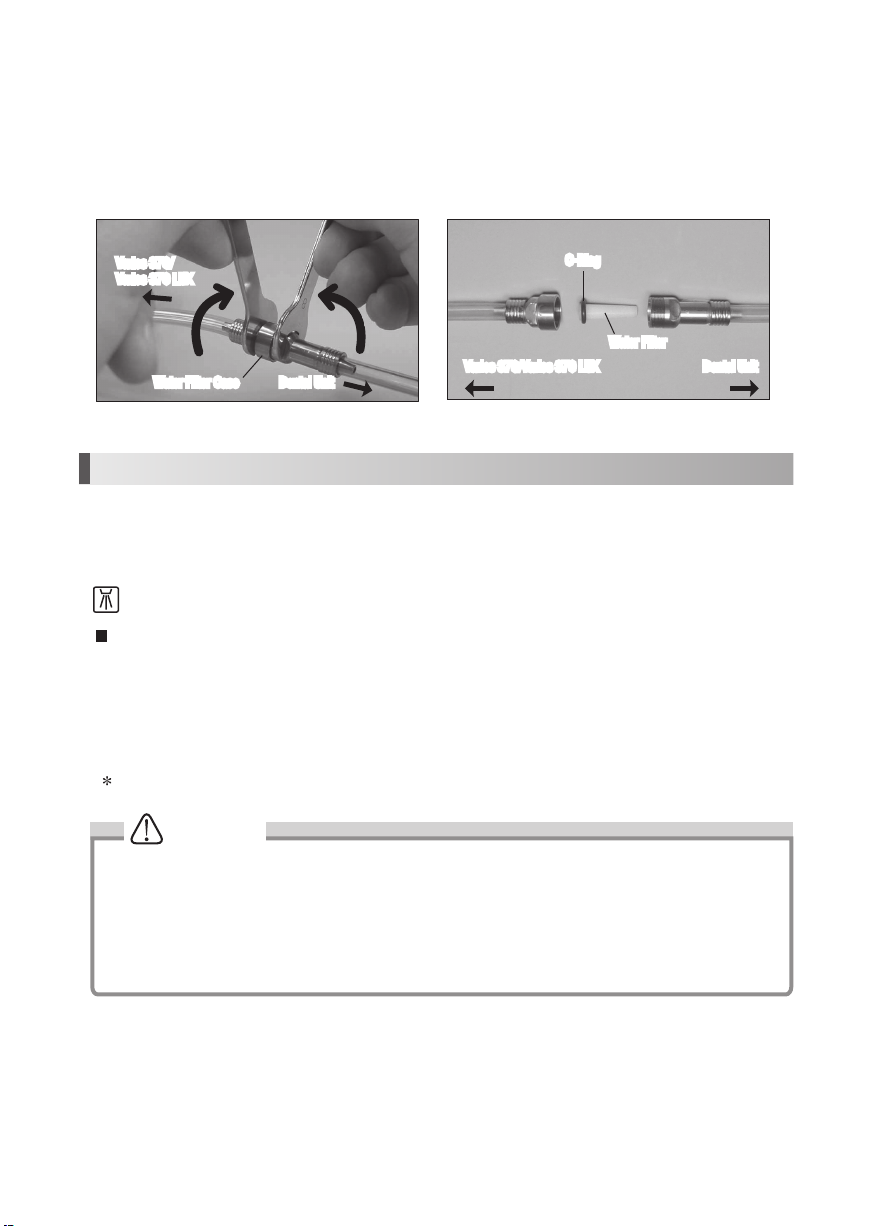
10-3 Changing Water Filter (Option)
Change the Water Filter as it may necessary.
1) Close the water valve of the Chair Unit.
2) Mount two Spanner Wrenches (5x8)and turn those as shown in Fig.21.
3) When the Water Filter case is separated, the Water Filter can be removed as shown in Fig. 22.
4) Replace with new (Order Code U387 042)and reassemble the filter in the reverse order.
This handpiece can be cleaned and disinfected with a Thermo-Disinfector.
Fig.21 Fig.22
O-Ring
Water Filter
Varios 370/Varios 370 LUX
Water Filter Case
Dental Unit
Dental Unit
Varios 370/
Varios 370 LUX
English
13
12. Troubleshooting
When trouble is found, please check the followings prior to consulting your dealer.
Problem Probable Cause Cause Solution
No / Poor
vibration
The Power
Indicator does
not on,even if
the power is ON
The AC Adaptor or the DC Plug is
disconnected
Correctly insert the AC Adaptor or the DC Plug
The Tip does
not generate
vibration, in spite
of depressing
the Foot Control
The Tip is not tightened firmly Tighten the Tip until the Tip Wrench clicks
Worn Tip Replace the Tip
Power has not been correctly
adjusted for the Tip
Adjust the power level the Power Guide or Tip
case label. Do not exceed
The Foot Control is disconnected Connect the Foot Control correctly
Failure of vibrator in the handpiece Contact dealer*
Failure of internal components of the
Foot Control
Contact dealer*
The Tip is bent or
broken —Power has not been properly adjusted
for the Tip
Adjust the power level the Power Guide or Tip
case label. Do not exceed
The Tip is flying
away —The Tip is not tightened firmly Tighten the Tip until the Tip Wrench clicks
Noise from the
handpiece —
Power has not been properly adjusted
for the Tip
Adjust the power level on the Power Guide or Tip
case label. Do not exceed
The Tip is not tightened firmly Tighten the Tip until the Tip Wrench clicks
Failure of vibration in the handpiece
or the Control Unit
Contact dealer*
The handpiece is
overheating —
Power has not been properly adjusted
for the Tip
Adjust the power level on the Power Guide or Tip
case label. Do not exceed
The Tip is not tightened firmly Tighten the Tip until the Tip Wrench clicks
Failure of vibration in the handpiece
or the Control Unit
Contact dealer*
No / Poor water
The water does
not reach to the
Control Unit
—Check the water circuitry and supply to the Control
Unit. Water pressure : 0.1-0.5MPa (1-5kgf/cm2)
Check to see if
water reaches
the Control Unit
The Water Adjustment Knob is
closed.
Turn the Water Volume Knob and adjust to the
appropriate volum
Disconnected Irrigation supply at low
volume range. (less than 10ml/min.)
No problem. Turn the Water Volume Knob and
increase the Irrigation volume
The Water Filter is clogged Replace with new Water Filter (Refer to 9-3
Changing Water Filter (Option) )
Water leakage
Water is leaking
from the joint
between the
handpiece and
the cord
O-Ring at the handpiece cord is worn
or damaged
Replace with new O-Ring (Refer to 9-2 Changing
O-Ring Handpiece Cord)
Attachment of
the Control Unit
Holder is loose
—The click of a holder was worn out Contact dealer*
14
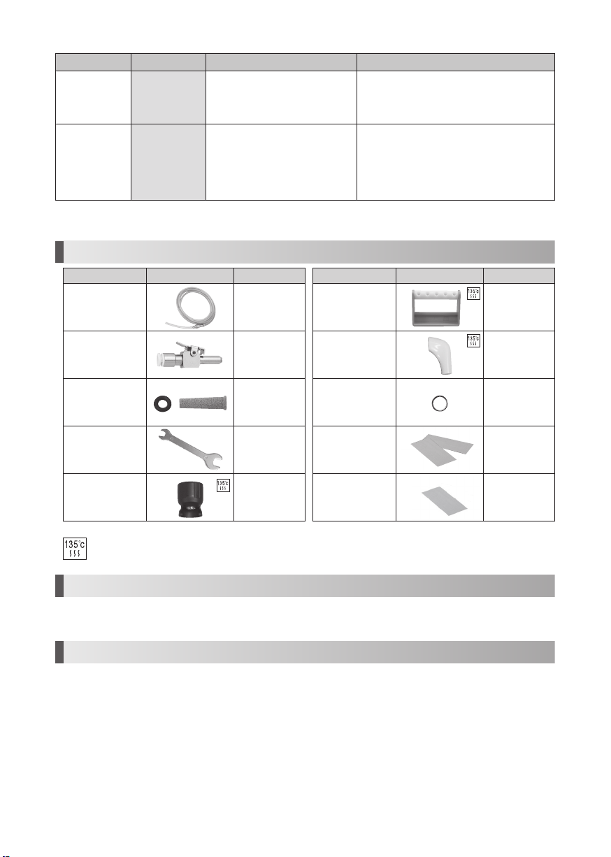
13. Spare Parts
Model Products Order code
Water Tube Set U1007080
Water Supply
Connector U387030
Water Filter U387042
Spanner Wrench
(5x8) X 2 pcs Y1001301
Tip Wrench
(CR-10) Z221076
Model Products Order code
Tip Holder Z221080
Tip Cover S Z217851
O-Ring 0310020080
Double-Face Tape
(For Control Unit Holder)20002545
Double-Face Tape
(For Handpiece Holder)20002544
Autoclavable up to max 135°C.
14. Disposing product
Consult with dealer from whom you purchased it about waste disposal.
15. Warranty
Manufacturer warrants its products to the original purchaser against defects in material and workmanship under normal
practices of installation, use and servicing. Such expendable items as O-Rings are not covered by this warranty.
Problem Probable Cause Cause Solution
Handpiece
LED does not
illuminate.
(Varios2 Lux)
Tip oscillates, but
Handpiece LED
turns on and off
The handpiece is not connected into
the Handpiece Cord correctly
Firmly insert the handpiece into the Handpiece
Cord inmost
Loss of the power
output without
operation
Power output is
set 8 at G Safety function is activated
Powerful output will weaken automatically while
continuous operation is over 10min at the setting
of Maximum power at G mode. Releasing the foot
from the Foot Control. Decrease the Power less
than 5, once then increase the power again. (Refer
to 7-5)
* Repairs cannot be made by the customer.

English
15
Symbols
TUV Rhineland of North America is a Nationally Recognized Testing Laboratory (NRTL) in the United States and is accredited by
the Standards Council of Canada to certify electro-medical products with Canadian National Standards.
Follow the waste of electric and electronic equipment (WEEE) Directive (2002/96/EC) to dispose of the product and
accessories.
Consult operation instructions. Manufacturer.
This conforms to CE European Directive of “Medical equipment directive 93/42/EEC.”
Type BF applied part. Authorised representative in
the European community.
Protected against vertically falling water
drops.
Autoclavable up to Max.135°C. *for detail see
Sterilization.
Marking on the outside of Equipment or Equipment parts that include RF transmitters or that apply RF electromagnetic energy
for diagnosis or treatment.
Guidance and manufacturer's declaration - electromagnetic immunity
The Varios 370 / Varios 370 Lux is intended for use in the electromagnetic environment specified below. The customer or the user of the Varios 370 / Varios 370 Lux
should assure that it is used in such an environment.
Immunity test EN/IEC60601 test level Compliance level Electromagnetic environment - guidance
Electrostatic discharge (ESD)
EN/IEC61000-4-2
±6kV contact
±8kV air
±6kV contact
±8kV air
Floors should be wood, concrete or ceramic tile. If floors are
covered with synthetic material, the relative humidity should
be at least 30%.
Electrical fast transient/burst
EN/IEC61000-4-4
±2kV for power supply lines
±1kV for input/output
±2kV for power supply lines
±1kV for input/output
Mains power quality should be that of a typical commercial or
hospital environment.
Surge
EN/IEC61000-4-5
±1kV line(s) to line(s)
±2kV line(s) to earth
±1kV line(s) to line(s)
±2kV line(s) to earth
Mains power quality should be that of a typical commercial or
hospital environment.
Voltage dips, short
interruptions and voltage
variations on power supply
input lines
EN/IEC61000-4-11
<5% Ut (>95% dip in Ut)
for 0.5 cycle
40% Ut (60% dip in Ut)
for 5 cycles
70% Ut (30% dip in Ut)
for 25 cycles
<5% Ut (>95% dip in Ut)
for 5 secs
<5% Ut(>95% dip in Ut)
for 0.5 cycle
40% Ut (60% dip in Ut)
for 5 cycles
70% Ut (30% dip in Ut)
for 25 cycles
<5% Ut (>95% dip in Ut)
for 5 sec
Mains power quality should be that of a typical commercial
or hospital environment. If the user of the Varios 370 / Varios
370 Lux requires continued operation during power mains
interruptions, it is recommended that the Varios 370 / Varios
370 Lux be powered from an uninterruptible power supply or
a battery.
Power frequency (50/60Hz)
magnetic field
EN/IEC61000-4-8
3 A/m 3 A/m Power frequency magnetic fields should be at levels
characteristic of a typical location in a typical commercial or
hospital environment.
NOTE: Ut is the a.c. mains voltage prior to application of the test level.
Class II Equipment.
Guidance and manufacturer's declaration - electromagnetic emissions
The Varios 370 / Varios 370 Lux is intended for use in the electromagnetic environment specified below. The customer or the user of the Varios 370 / Varios 370 Lux
should assure that is used in such an environment.
Emissions test Compliance Electromagnetic environment - guidance
RF emissions
CISPR11/EN55011 Group 1 The Varios 370 / Varios 370 Lux uses RF energy only for its internal function. Therefore, its RF emissions are
very low and are not likely to cause any interference in nearby electronic equipment.
RF emmissions
CISPR11/EN55011 class B The Varios 370 / Varios 370 Lux is suitable for use in all establishments, including domestic establishments
and those directly connected to the public low-voltage power supply network that supply network that
supplies buildings used for domestic purposes.
Harmonic emissions
EN/IEC61000-3-2 class A
Voltage fluctuations/flicker emissions
EN/IEC61000-3-3 Complies
This product can be cleaned and disinfected with a
Thermo-Disinfector.

16
Guidance and manufacturer's declaration - electromagnetic immunity
The Varios 370 / Varios 370 Lux is intended for use in the electromagnetic environment specified below. The customer or the user of the Varios 370 / Varios 370 Lux
should assure that it is used in such an environment.
Immunity test EN/IEC60601 test level Compliance level Electromagnetic environment - guidance
Conducted RF
EN/IEC61000-4-6
Radiated RF
EN/IEC61000-4-3
3Vrms
150 kHz to 80MHz
3V/m
80MHz to 2.5 GHz
3Vrms
3V/m
Portable and mobile RF communications equipment should be used
no closer to any part of the Varios 370 / Varios 370 Lux, including
cables, than the recommended separation distance calculated from
the equation applicable to the frequency of the transmitter.
Recommended separation distance
d = 1.2 P
d = 1.2 P 80MHz to 800MHz
d = 2.3 P 800MHz to 2.5GHz
Where P is the maximum output power rating of the transmitter in
watts (W) according to the transmitter manufacturer and d is the
recommended separation distance in meters (m).
Field strengths from fixed RF transmitters as determined by an
electromagnetic site survey, should be less than the compliance level
in each frequency range.
Interference may occur in the vicinity of equipment
marked with the following symbol:
NOTE 1 At 80MHz and 800MHz, the higher frequency range applies.
NOTE 2 These guidelines may not apply in all situations. Electromagnetic propagation is affected by absorption and reflection from structures, objects and people.
aField strengths from fixed transmitters, such as base stations for radio (cellular/cordless) telephones and land mobiles radios, amateur radio, AM and FM
radio broadcast and TV broadcast cannot be predicted theoretically with accuracy.To assess the electromagnetic environment due to fixed RF transmitters, an
electromagnetic site survey should be considered. If the measured field strength in the location in which the Varios 370 / Varios 370 Lux is used exceeds the
applicable RF compliance level above, the Varios 370 / Varios 370 Lux should be observed to verity normal operation. If abnormal performance is observed,
additional measures may be necessary, such as reorienting or relocating the Varios 370 / Varios 370 Lux.
bOver the frequency range 150kHz to 80MHz, field strengths should be less than 3 V/m.
Cables and accessories Maximum length Complies with
Handpiece cord
Foot Control
AC Adaptor
2 m (Unshielded)
5 m (Unshielded)
5 m (Unshielded)
RF emissions, CISPR11, EN55011
Harmonic emissions,
Voltage fluctuations/ flicker emission,
Electrostatic discharge (ESD)
Electric fast transient / burst
Surge
Voltage dips, short interruptions and voltage variations on power supply input lines
Power frequency(50/60Hz) magnetic field
Conducted RF
Radiated RF
Class B/ Group 1
EN/IEC61000-3-2
EN/IEC61000-3-3
EN/IEC61000-4-2
EN/IEC61000-4-4
EN/IEC61000-4-5
EN/IEC61000-4-11
EN/IEC61000-4-8
EN/IEC61000-4-6
EN/IEC61000-4-3
Recommended separation distances between portable and mobile RF communications equipment and the Varios 370 / Varios 370 Lux.
The Varios 370 / Varios 370 Lux is intended for use in an electromagnetic environment in which radiated RF disturbances are controlled. The customer or the user of
the Varios 370 / Varios 370 Lux can help prevent electromagnetic interference by maintaining a minimum distance between portable and mobile RF communications
equipment (transmitters) and the Varios 370 / Varios 370 Lux as recommended below, according to the maximum output power of the communications equipment.
Rated maximum output power of transmitter
W
Separation distance according to frequency of transmitter
m
150kHz to 80MHz
d=1.2 P
80MHz to 800MHz
d=1.2 P
800MHz to 2.5GHz
d=2.3 P
0.01 0.12 0.12 0.23
0.1 0.38 0.38 0.73
1 1.2 1.2 2.3
10 3.8 3.8 7.3
100 12 12 23
For transmitters rated at a maximum output power not listed above, the recommended separation distance d in meters (m) can be estimated using the equation
applicable to the frequency of the transmitter, where P is the maximum output power rating of the transmitter in watts (W) according to the transmitter manufacturer.
NOTE 1 At 80 MHz and 800 MHz, the separation distance for the higher frequency range applies.
NOTE 2 These guidelines may not apply in all situations. Electromagnetic propagation is affected by absorption and reflection from structures, objects and people.
17
DEUTSCH
Vorsichtsmaßregeln für Handhabung und Bedienung
Lesen Sie diese Vorsichtsmaßregeln sorgfältig durch und verwenden Sie das Gerät nur bestimmungsgemäß bzw. gemäß
der Anleitung.
Die Sicherheitsvorschriften dienen zum Vermeiden möglicher Gefahren, die zu Verletzungen oder einer Beschädigung des
Geräts führen könnten. Die Sicherheitsvorschriften werden entsprechend des Risikogrades wie folgt eingestuft.
· Stecken Sie das Anschlusskabel nicht mit nassen Händen aus, um einen Stromschlag zu vermeiden.
· Achten Sie darauf, dass die Steuereinheit nicht mit Wasser in Berührung kommt, da dies zu einem Kurzschluss und einem
Stromschlag führen kann.
· Berühren Sie das hintere Ende des Handstücks nicht, wo elektrische Anschlüsse mit dem Kabel verbunden sind. Dies
könnte zu einem Stromschlag führen.
· Wenn Sie vor oder während des Betriebs des Geräts eine Anormalität wie z.B. Vibrationen, Wärmeentwicklung, unnormale
Geräusche etc. feststellen, schalten Sie das Geärt sofort ab.
· Verwenden Sie eine geerdete Steckdose. Es kann zu einem Stromschlag kommen, wenn Sie eine andere verwenden.
· Dieses Gerät ist ein medizinisches Elektrogerät. Die EMK (elektromagnetische Kompatibilität) wird in der
Begleitdokumentation beschrieben.
· Tragbare und mobile RF-Kommunikationsgeräte können das medizinische Elektrogerät beeinträchtigen. Verwenden Sie
keine RF-Geräte in der Umgebung des Geräts.
· Sehen Sie beim Installieren des Geräts Platz von circa 10 cm um die Steuereinheit herum vor, damit der Zulauf und das
Anschlusskabel einfach zugänglich sind.
· Verwenden Sie nur echte NSK-Aufsätze für den NSK Varios Ultraschallscaler (Varios 370 oder Varios 370 Lux). Probleme
wie zum Beispiel eine Beschädigung, ein Ausfall oder eine Störung von Handstücken aufgrund der Verwendung von
anderen als NSK-Aufsätzen werden von der Garantie nicht abgedeckt. Im Folgenden finden Sie mögliche Fehler, die beim
·
Verwenden von anderen als NSK-Aufsätzen auftreten können.
– Schwingungsbruch, verursacht durch die Verwendung nicht konformer Schrauben.
WARNUNG
Klassifizierung der Geräte
• Schutzart gegen Stromschlag :
– Geräteklasse II
• Schutzart gegen Stromschlag :
– Anwendungsteil Typ BF:
• Vom Hersteller empfohlenes Verfahren zum Sterilisieren oder Desinfizieren :
– Siehe 11. Sterilisation
• Schutzart gegen Eindringen von Wasser gemäß der Beschreibung in der aktuellen Ausgabe von IECD 60529:
– Fußschalter : IPX1 (gegen senkrecht herunterfallende Wassertropfen geschützt)
• Grad der Anwendungssicherheit bei Verwendung einer entflammbaren Betäubungsmittelmischung mit Luft oder mit
Sauerstoff oder Lachgas :
– GERÄT ist nicht zur Verwendung mit einer entflammbaren Betäubungsmittelmischung mit Luft oder mit Sauerstoff oder
Lachgas geeignet.
• Betriebsart :
– Dauerbetrieb
Bestimmungsgemäßer Gebrauch
Dieses Gerät ist nur zum Gebrauch in Zahnkliniken / Zahnarztpraxen bestimmt. Dieses Gerät erzeugt Ultraschallwellen, die
für Dentalanwendungen wie zum Beispiel Scaling, Wurzelkanalbehandlung, Paradontalbehandlung und Zahnpräparationen
bestimmt sind.
KLASSE RISIKOGRAD
WARNUNG Eine Gefahr, die zu Verletzungen oder zu einer Beschädigung des Geräts führen können, wenn die
Sicherheitsvorschriften nicht befolgt werden.
ACHTUNG Eine Gefahr, die zu leichten oder mittelschweren Verletzungen oder einer Beschädigung des Geräts
führen können, wenn die Sicherheitsvorschriften nicht befolgt werden.
HINWEIS Allgemeine Informationen für den sicheren Betrieb des Geräts.
Bedienungsanleitung

18
– Patient verschluckt versehentlich beschädigte Aufsätze.
– Beschädigung des Gewindes am Handstück.
·
Sie müssen den Aufsatz innerhalb des in der Leistungsrichtlinie für Aufsätze beschriebenen Leistungsbereichs verwenden.
Wenn Sie ihn außerhalb des Leistungsbereichs verwenden, könnte der Aufsatz abbrechen oder eine Operationsstelle
geschädigt werden.
·
Denken Sie beim Verwenden des Geräts stets an die Sicherheit des Patienten.
·
Es ist zur Verwendung durch medizinisches Fachpersonal wie zum Beispiel durch einen Arzt/eine Ärztin oder einen
Dentalhygieniker /eine Dentalhygienikerin bestimmt.
·
Überprüfen Sie vor dem Verwenden die Vibrationen außerhalb des Mundes des Patienten. Sollte Ihnen etwas unnormal
vorkommen, stellen Sie die Verwendung sofort ein und setzen Sie sich mit Ihrem Händler in Verbindung.
·
Die Steuereinheit / das Handstück darf nicht fallen gelassen oder starken Erschütterungen ausgesetzt werden.
·
Verwenden Sie immer ausreichend Wasser (Kühlmittel), da es sonst zu einer Schädigung der Zahnoberfläche und einer
Überhitzung des Handstücks kommen kann.
·
Sterilisieren Sie es nicht mit ultraviolettem Licht. Das Handstück könnte sich verfärben.
·
Sterilisieren Sie den Aufsatz, das Handstück und den Drehmomentschlüssel mit dem Autoklaven. Wischen Sie die
Steuereinheit, das Wechselstrom-Anschlusskabel, den Fußschalter und das Handstückkabel mit DSH gelisteter
Desinfektionslösung ab.
·
Wenn chemische Lösungen, Lösungsmittel oder antiseptische Lösung an dieses Gerät gelangen, wischen Sie es sofort ab.
Sonst kann es zu einer Verfärbung oder Verformung kommen.
·
Das Handstück/die Steuereinheit darf nicht auseinandergenommen oder verändert werden.
·
Halten Sie das Gerät von Patienten mit einem Herzschrittmacher fern.
·
Halten Sie das Gerät von explosiven Stoffen und entflammbarem Material fern. Verwenden Sie es nicht für Patienten, die
mit Lachgas betäubt werden.
·
Für dieses Gerät gelten besondere Vorsichtsmaßregeln bezüglich der EMK und es muss entsprechend den EMK-Daten
installiert und in Betrieb genommen werden.
·
Die Verwendung von anderen ZUBEHÖRTEILEN, Wandlern und Kabeln als den hier angegebenen kann, mit Ausnahme
on Wandlern und Kabeln, die vom Gerätehersteller als Ersatzteile für Einbauteile verkauft werden, zu einer vermehrten
EMISSION oder einer verringerten STÖRFESTIGKEIT dieses Geräts führen.
·
Dieses Gerät sollte nicht direkt neben, auf oder unter anderen Geräten aufgestellt werden, und wenn es direkt neben,
unter oder auf anderen Geräten verwendet werden muss, muss sichergestellt werden, dass das Gerät in der Konfiguration,
in der es verwendet werden soll, normal funktioniert.
·
Wenn nach dem Autoklavieren noch Wassertropfen am Handstück oder am
Handstückkabel sind, wischen Sie sie ab.Wenn Sie sie nicht abwischen, können
sich Flecken bilden.
·
Dieses Gerät darf nicht vom Patienten benutzt werden.
·
Eine zuverlässige Erdung kann nur erreicht werden, wenn die Ausrüstung
an einer Anschlussdose mit der Kennzeichnung "Nur Krankenhaus" oder
"Krankenhaus-Grad" angeschlossen wird.
· Während des Betriebes können das Handstück und das Handstückkabel Computer und LAB-Kabel beeinflussen. Es kann
zu einem Rauschen kommen, wenn es neben einem Rundfunkgerät betrieben wird.
· Stellen Sie sicher, dass der Hauptschalter am Gerät nach der Benutzung ausgeschaltet wird. Ziehen Sie den Netzstecker
und lassen Sie das Wasser aus dem Inneren der Steuereinheit ab, wenn sie für längere Zeit nicht verwendet wird.
· Der Benutzer ist für die Bedienung, Wartung und Inspektion verantwortlich.
· Reinigen/ sterilisieren Sie das Gerät direkt nach dem Verwenden. Dann lagern Sie es ein. Wenn Blut etc. darauf verbleibt,
kann dies zu einem Ausfall führen.
· Wenn Sie das Gerät längere Zeit nicht verwendet haben und es erneut einsetzen möchten, überprüfen Sie es vor dem
Einsatz auf seine Funktionstüchtigkeit.
· Schauen Sie nicht in die LED-Lampe und lassen Sie die Patienten nicht hineinschauen. Dies kann zu einer Schädigung der
Augen führen.
· Wenn irgendwelche Abweichungen an einer Steuereinheit oder einem AC-Adapter festgestellt werden, müssen Sie sofort
den AC-Adapter aus dem AC-Ausgang ziehen.
· Dieses Gerät kann für Patienten jeden Alters (außer Kleinkinder), Geschlechts, Gewichts und jeder Staatsangehörigkeit
verwendet werden.
· Für dieses Gerät ist keine besondere Schulung erforderlich.
· Anwendungsteile, die mit dem Patienten bzw. Bediener in Berührung kommen, sind Aufsatz bzw. Handstück.
· Oberflächentemperatur der Spitze ist mehr als 50 Grad, ohne einen Leitungswaßer zu verwenden. Um dieses Ereignis zu
vermeiden, seien Sie sicher einen Leitungswaßer zu benutzen.
HINWEIS
Netzstecker unten wird in
Nordamerika verwendet.
Steckertyp NEMA 1-15P
(Hospital Grade Type)
19
Deutsch
1. Bezeichnung der Komponenten
1 Die Form des Wechselstromkabeladapters wurde geändert
2 Ein von beiden man wird mit dem Satz enthalten, den Sie kauften.
3 Nur 120 V
3
1 Steuereinheit (mit Nicht abgeschirmtes Kabel 2M) 1
2Varios2 Handstück (mit oder ohne Licht) 1
2
3 Bedieneinheithalterung 1
4
1Wechselstrom-Anschlusskabel 1
5 Handstückhalter 1
6 Doppelseitiges Klebeband 2
7 Fußschalter 1
8 Wasserschlauch 1
9 Aufsatz (G4,G6, G8)1
10 Gummiauflagun 4
11 Drehmomentschlüssel 1
12
Schraubenschlüssel
(5x8)2
13 O Ring 2
14 Aufsatzschutz kurz (Option)-
15 Aufsatzhalter (Option)-
Gleichstromstecker
* Arbeitsprinzip
Der Generator erzeugt bei Ultraschallfrequenz ein sinusförmiges elektrisches Signal. Dieses Signal wird an die
Piezokeramik im Wandler angelegt. Die Piezokeramik wandelt dieses Signal in mechanische Schwingungen um. Diese
Schwingungen haben dieselbe Ultraschallfrequenz wie das elektrische Signal. Die mechanischen Schwingungen
breiten sich zum distalen Ende des Wandlers hin aus. Der Einsatz, der am distalen Ende des Wandlers angebracht ist,
vibriert mit Ultraschallfrequenz und ermöglicht das Erreichen des angestrebten Zieles.
Other manuals for Varios 370
1
Table of contents
Languages:
Other NSK Media Converter manuals


