SEW-Eurodrive EI7 Series User manual

*21362599_0215*
Drive Technology \ Drive Automation \ System Integration \ Services
Service Kit
EI7. Encoder
Edition 02/2015 21362599/EN

SEW-EURODRIVE—Driving the world

Contents
Service Kit – EI7. Encoder 3
Contents
1Service kit content..................................................................................................................... 4
2Procedure................................................................................................................................... 5
2.1 Recommended accessories ........................................................................................... 5
2.2 Disposal ......................................................................................................................... 5
3Conversion of encoder generation A to encoder generation B ............................................ 6
3.1 Without brake ................................................................................................................. 6
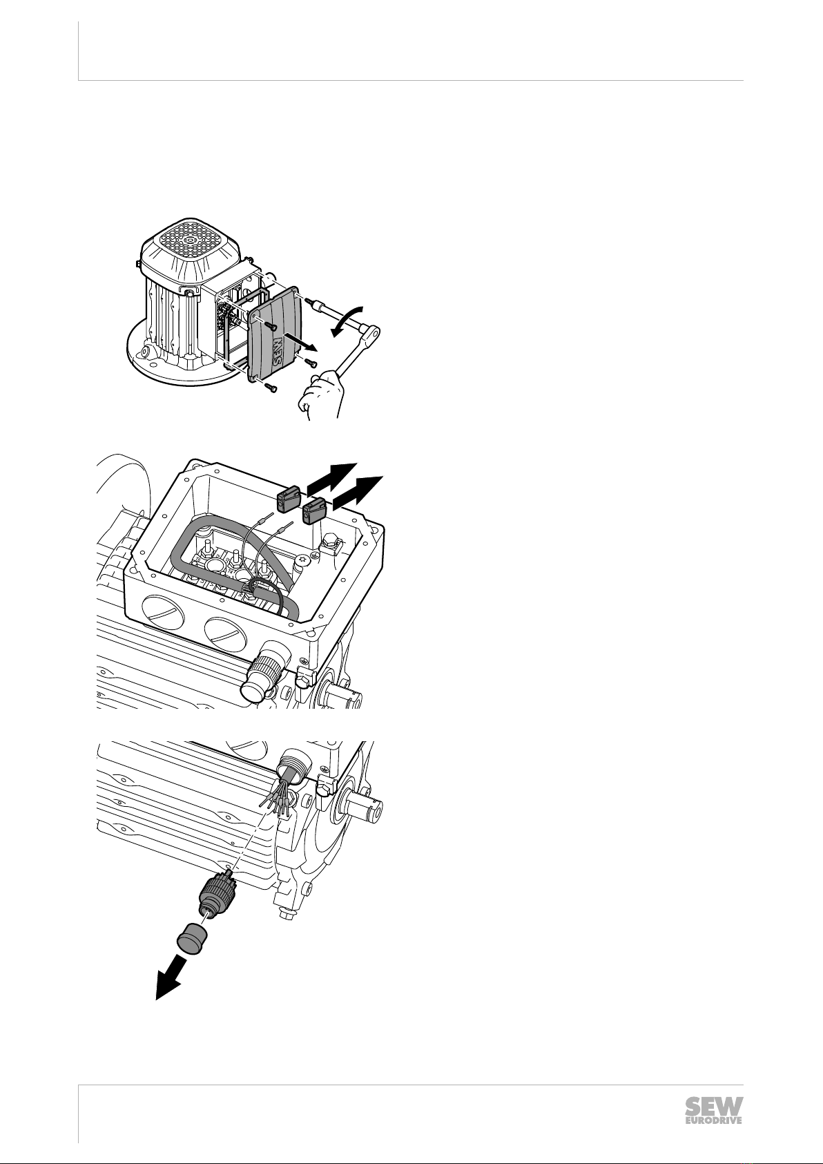
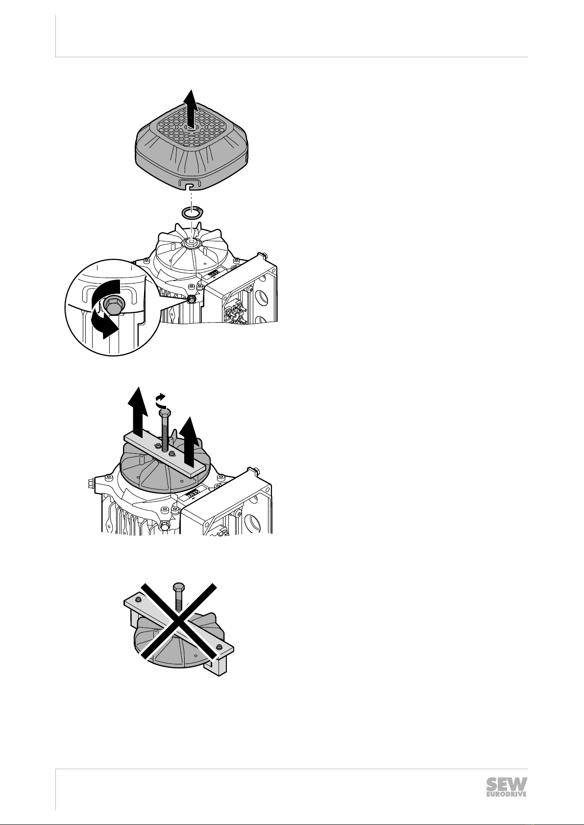
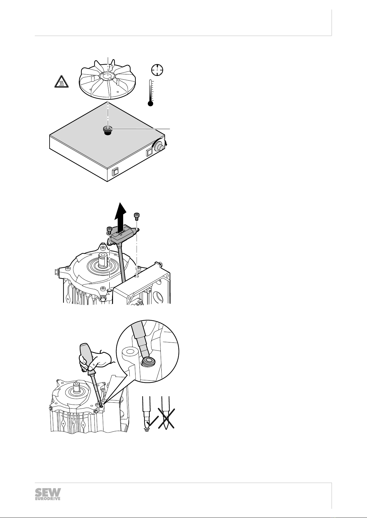
3.1.1 Removal of the EI7.A encoder ........................................................................ 6
3.1.2 Installation of the new EI7.B encoder ........................................................... 10
3.1.3 Wiring the EI7.B encoder to the connection box........................................... 11
3.1.4 Wiring the EI7.B encoder to the connection unit........................................... 15
3.2 With brake .................................................................................................................... 18
3.2.1 Removal of the EI7.A encoder ...................................................................... 18
3.2.2 Installation of the new EI7.B encoder ........................................................... 22
3.2.3 Wiring the EI7.B encoder to the connection box........................................... 24
3.2.4 Wiring the EI7.B encoder to the connection unit........................................... 28
4Replacement of encoder generation B with encoder generation B.................................... 31
4.1 Without brake ............................................................................................................... 31
4.1.1 Removal of the EI7.B encoder ...................................................................... 31
4.1.2 Installation of the new EI7.B encoder ........................................................... 35
4.1.3 Wiring the EI7.B encoder to the connection box........................................... 37
4.1.4 Wiring the EI7.B encoder to the connection unit........................................... 41
4.2 With brake .................................................................................................................... 44
4.2.1 Removal of the EI7.B encoder ...................................................................... 44
4.2.2 Installation of the new EI7.B encoder ........................................................... 49
4.2.3 Wiring the EI7.B encoder to the connection box........................................... 50
4.2.4 Wiring the EI7.B encoder to the connection unit........................................... 54
5Appendix .................................................................................................................................. 57
5.1 Pin assignment for 8-pin M12 connector (AVRE) ........................................................ 57
5.1.1 Connection box ............................................................................................. 57
5.1.2 Connection via M12 connector ..................................................................... 57
5.2 Pin assignment for 4-pin M12 connector (AVSE) ......................................................... 58
5.2.1 Connection box ............................................................................................. 58
5.2.2 Connection via M12 connector ..................................................................... 58
5.3 Pin assignment without M12 connector ....................................................................... 59
5.3.1 Connection unit ............................................................................................. 59
21362599/EN – 02/2015

1Service kit content
Service Kit – EI7. Encoder
4
1Service kit content
[1525]
[1529]
[1539]
[1546]
[1534]
[1545]
[1517]
[1520] [1518][1526] [36]
[1635]
[1552]
[1524]
[119]
[632]
[1522]
[129]
[131]
[132]
[112]
[1632]
18014401416894731
The different EI7.B service kits "Connection box with M12 connector" or "Connec-
tion unit without M12 connector" have the following part numbers and contain the
following parts:
Connection box with M12 connector Connection unit without M12 connector
Motor Part number Motor Part number
DR..71: 28214366 DR..71: 28214404
DR..80, DRN80: 28214374 DR..80, DRN80: 28214420
DR..90 – 100, DRN90: 28214382 DR..90 – 100, DRN90: 28214447
DR..112 – 132, DRN112 –
132S:
28214390 DR..112 – 132, DRN112 –
132S:
28214463
DRN100 28225562 DRN100 28225554
Connection box with M12 connector Connection unit without M12 connector
Item Designation Item Designation
[1517] Encoder module [119] Screw M5x20
[1518] Screw M5x10 [632] Screw M4x8
[1520] Spacer [1517] Encoder module
[9997] Spacer [1518] Screw M5x10
[9998] Hex nut M4 [1520] Spacer
[1524] Terminal washer [9997] Spacer
[1526] Grommet [9998] Hex nut M4
[1534] Glass fiber sheathing Ø10 mm,
long
[1522] Connection unit
[1552] Glass fiber sheathing Ø7 mm,
short
[1524] Terminal washer
[1632] Connection box [1526] Grommet
[1635] Cable ties [1635] Cable ties
21362599/EN – 02/2015

2
Procedure
Recommended accessories
Service Kit – EI7. Encoder 5
2Procedure
The following table is used to help find the correct encoder installation description:
Type of installation
DR../DRN.. motors with encoder gener-
ation A and endshield generation A
DR../DRN.. motors with encoder gener-
ation B and endshield generation B
Conversion
of EI7. generation A to EI7. generation B
Replacement of
EI7. generation B
Motor without
brake
Distinguishing features:
• EI7.A encoder
• End shield generation A (M5)
Distinguishing features:
• EI7.B encoder
• End shield generation B (M4)
Motor with brake/
backstop
Distinguishing features:
• EI7.A encoder
• End shield generation A (M5)
• Spacing bushings
Distinguishing features:
• EI7.B encoder
• End shield generation B (M4)
• Spacers
Encoder identification (generation A or generation B):
Generation A Generation B
Designation on the nameplate: EI7. Designation on the nameplate: EI7.B
2.1 Recommended accessories
SEW‑EURODRIVE recommends the following accessories for the work to be per-
formed:
• Molykote® assembly paste from Dow Corning
• LUB-I wire lubricant from 3M
• 0.4 x 2.0 mm screw driver from Phoenix Contact, manufacturer part number
1205202
2.2 Disposal
Dispose of waste separately in accordance with the applicable regulations, for exam-
ple: iron, aluminum, copper, plastic, electronic components, oil and grease (not mixed
with solvents).
21362599/EN – 02/2015

3Conversion of encoder generation A to encoder generation B
Without brake
Service Kit – EI7. Encoder
6
3Conversion of encoder generation A to encoder generation B
3.1 Without brake
3.1.1 Removal of the EI7.A encoder
9007208700802827
• Loosen the screws on the terminal box and re-
move the terminal box cover.
9007208700732811
If a connection box with a 4-pin M12 connector is
used:
• Remove the terminals on the encoder cables.
• Dispose of the terminals.
This step is not necessary if a connection box with
an 8-pin M12 connector is used.
9007208763132939
• Unscrew the M12 connector.
• Disconnect the conductors of the encoder ca-
ble from the M12 connector.
21362599/EN – 02/2015

3
Conversion of encoder generation A to encoder generation B
Without brake
Service Kit – EI7. Encoder 7
9007208846667659
If a connection unit without M12 connector is
used:
• Disconnect the conductors of the encoder ca-
ble from the wiring terminal.
• Loosen the screws in the terminal box and re-
move the wiring terminal.
• Dispose of the wiring terminal.
9007208700736651
• Loosen the screw for fastening the shielding
on the terminal box.
• Bend the terminal washer open and remove
the encoder cable shielding together with the
conductor end sleeve.
• Dispose of the terminal washer.
21362599/EN – 02/2015

3Conversion of encoder generation A to encoder generation B
Without brake
Service Kit – EI7. Encoder
8
1.
2.
3.
9445974539
• Loosen the screws on the fan guard and re-
move the fan guard.
• Remove the retaining ring of the plastic fan.
9445978379
9744815115
• Apply a puller to the bushing of the plastic fan
and remove the plastic fan.
Notice: Applying direct force to the plastic fan can
damage it.
21362599/EN – 02/2015

3
Conversion of encoder generation A to encoder generation B
Without brake
Service Kit – EI7. Encoder 9
80 °C
> 1 min.
<
[1]
9007208700734731
• Place the bushing of the plastic fan on a warm-
ing plate and heat it up to a maximum temper-
ature of 80°C.
While doing so, ensure that the plastic fan does
not come into direct contact with the warming
plate.
Any thermally conductive component [1] (e.g. a
metal ring) can be used as a contact surface.
This step is necessary for re-assembly.
9445970699
• Loosen the screws on the encoder and re-
move the encoder.
• Dispose of the screws.
9445989899
• Remove the old grommet from the cable bush-
ing of the terminal box.
• Dispose of the old grommet.
21362599/EN – 02/2015

3Conversion of encoder generation A to encoder generation B
Without brake
Service Kit – EI7. Encoder
10
3.1.2 Installation of the new EI7.B encoder
[1526]
Ø ≤ 12 mmØ 3.7 mm
[1517]
9446005259
• Push the grommet [1526] onto the cable end of
the encoder module [1517]. The inside diame-
ter of the grommet may not exceed the maxi-
mum inside diameter of 12 mm.
3M Lub-I
r > 28 mm
1.
2.
9445987979
• Coat the cable jacket with wire lubricant. Using
a rotating movement, carefully pull the cable
through the grommet into the terminal box.
While doing so, ensure that the grommet does
not inadvertently slide through into the terminal
box.
The minimum bending radius of 28 mm must be
observed.
21362599/EN – 02/2015

3
Conversion of encoder generation A to encoder generation B
Without brake
Service Kit – EI7. Encoder 11
[9997]
[9998]
9445997579
• Install the spacers [9997] on the end shield.
The tightening torque must be 5 Nm ± 10%.
• Fasten the encoder board onto the end shield
using 2 nuts [9998]. The tightening torque must
be 2.5 Nm ± 10%.
3.1.3 Wiring the EI7.B encoder to the connection box
[1534]
Ø10 mm
[S]
1.
Ø7 mm
2. [1552]
3.
[1524]
RD, BU,
WH, GN
GY, PK,
YE, BN
RD, BU,
WH, GN
GY, PK,
YE, BN
18014407973893771
4-pin:
• Push the long glass fiber sheathing [1534] over
the single conductors of the encoder cable.
Lay the shielding [S] in the opposite direction.
• Push the short glass fiber sheathing [1552]
over the single conductors.
• Install the terminal washer [1524].
21362599/EN – 02/2015

3Conversion of encoder generation A to encoder generation B
Without brake
Service Kit – EI7. Encoder
12
[1534]
Ø10 mm
1.
Ø7 mm
2. [1552]
RD, BU
GY, PK, BN,
WH, YE, GN
RD, BU
GY, PK, BN,
WH, YE, GN
3.
[1524]
[S]
18014407973891467
8-pin:
• Push the long glass fiber sheathing [1534] over
the single conductors of the encoder cable.
Lay the shielding [S] in the opposite direction.
• Push the short glass fiber sheathing [1552]
over the single conductors.
• Install the terminal washer [1524].
9007208763131019
• Route the conductors through the thread re-
duction out of the terminal box to the outside.
• Connect the M12 connector as shown in the
wiring diagram.
The wiring diagrams for 4 and 8-pin connectors
are included in the appendix (→ 2 57).
• Screw on and secure the conductors with the
M12 connector. The tightening torque must be
0.8 Nm ± 10%.
• Fasten the connector.
21362599/EN – 02/2015

3
Conversion of encoder generation A to encoder generation B
Without brake
Service Kit – EI7. Encoder 13
[1632]
9007208700748171
• Wire the connection box [1632] (in accordance
with the previously installed encoder type).
The wiring diagrams for 4 and 8-pin connectors
are included in the appendix (→ 2 57).
[1552]
9007208700723211
• Fasten the short glass fiber sheathing [1552]
using a cable tie.
• Fasten the connection box using a cable tie
[1635] as close to the conductor end sleeves
on the glass fiber sheathing as possible.
9007208700725131
• Screw on and secure the shielding on the ter-
minal box. The tightening torque must be 5 Nm
± 10%.
21362599/EN – 02/2015

3Conversion of encoder generation A to encoder generation B
Without brake
Service Kit – EI7. Encoder
14
MOLY-
COTE
1.
2.
3.
9445999499
• Apply assembly paste to the shaft.
• Install the plastic fan that has been heated.
• Fasten the plastic fan using a retaining ring.
2.
1.
9446001419
• Mount the fan guard and fasten it with screws.
The tightening torque must be 3.3 Nm ± 10%.
21362599/EN – 02/2015

3
Conversion of encoder generation A to encoder generation B
Without brake
Service Kit – EI7. Encoder 15
9007208718113291
• Mount the terminal box cover and fasten it with
screws. The tightening torque must be 3.5 -
4.0 Nm ± 10%.
3.1.4 Wiring the EI7.B encoder to the connection unit
TF
TF
1 < < 10
10 = GN
9 = YE
8 = WH
7 = BN
6 = PK
5 = GY
= B
= B
= A
= A
= GND
= +UB
EI71
EI72
EI76
EI7C
c1
c1
c1
c1
d4
d3
d2
d1
BU RD
14
c
d
BU
RD
9591928587
TF
TF
TF
9656059787
• Wire the connection unit [1522] in accordance
with the previously installed encoder type and
the applicable wiring diagrams.
The wiring diagrams for connection without M12
connector are included in the appen-
dix (→ 2 59).
21362599/EN – 02/2015

3Conversion of encoder generation A to encoder generation B
Without brake
Service Kit – EI7. Encoder
16
BU
RD
[1522]
[119] 5.0 Nm
[632] 1.8 Nm
9007208847313419
• Fasten the connection unit using screws [119]
or [632] (dependent on the terminal box). The
tightening torque must be 5.0 Nm ± 10% for
[119] and 1.8 Nm ± 10% for [632].
MOLY-
COTE
1.
2.
3.
9445999499
• Apply assembly paste to the shaft.
• Install the plastic fan that has been heated.
• Fasten the plastic fan using a retaining ring.
21362599/EN – 02/2015

3
Conversion of encoder generation A to encoder generation B
Without brake
Service Kit – EI7. Encoder 17
2.
1.
9446001419
• Mount the fan guard and fasten it with screws.
The tightening torque must be 3.3 Nm ± 10%.
9007208718113291
• Mount the terminal box cover and fasten it with
screws. The tightening torque must be 3.5 -
4.0 Nm ± 10%.
21362599/EN – 02/2015

3Conversion of encoder generation A to encoder generation B
With brake
Service Kit – EI7. Encoder
18
3.2 With brake
3.2.1 Removal of the EI7.A encoder
1234
aaaaa
5
12345
9592975883
• Loosen the screws on the terminal box and re-
move the terminal box cover.
9592968203
If a connection box with a 4-pin M12 connector is
used:
• Remove the terminals on the encoder cables.
• Dispose of the terminals.
This step is not necessary if a connection box with
an 8-pin M12 connector is used.
9007208847705355
• Unscrew the M12 connector.
• Disconnect the conductors of the encoder ca-
ble from the M12 connector.
21362599/EN – 02/2015

3
Conversion of encoder generation A to encoder generation B
With brake
Service Kit – EI7. Encoder 19
9592972043
If a connection unit without M12 connector is
used:
• Disconnect the conductors of the encoder ca-
ble from the wiring terminal.
• Loosen the screws in the terminal box and re-
move the wiring terminal.
• Dispose of the wiring terminal.
9592973963
• Loosen the screw for fastening the shielding
on the terminal box.
• Bend the terminal washer open and remove
the encoder cable shielding together with the
conductor end sleeve.
• Dispose of the terminal washer.
21362599/EN – 02/2015

3Conversion of encoder generation A to encoder generation B
With brake
Service Kit – EI7. Encoder
20
1234
aaaaa
5
12345
9592954763
• Loosen the screws on the fan guard and re-
move the fan guard.
1234
aaaaa
5
12345
9683086219
9744815115
• Apply a puller to the bushing of the plastic fan
and remove the plastic fan.
Notice: Applying direct force to the plastic fan can
damage it.
21362599/EN – 02/2015
This manual suits for next models
2
Table of contents
Other SEW-Eurodrive Media Converter manuals

SEW-Eurodrive
SEW-Eurodrive MOVIDRIVE compact MCH4_A User manual

SEW-Eurodrive
SEW-Eurodrive MOVITRANS TPM12B User manual

SEW-Eurodrive
SEW-Eurodrive MOVITRAC LTP-B Administrator guide

SEW-Eurodrive
SEW-Eurodrive DA70B User manual

SEW-Eurodrive
SEW-Eurodrive Movidrive MDX61B User manual

SEW-Eurodrive
SEW-Eurodrive MOVITRAC LTP User manual

SEW-Eurodrive
SEW-Eurodrive CMP40 User manual

SEW-Eurodrive
SEW-Eurodrive Movidrive MDX61B User manual

SEW-Eurodrive
SEW-Eurodrive MOVIDRIVE CES11A User manual

SEW-Eurodrive
SEW-Eurodrive DR.71-225 User manual