NSK Varios 150 User manual

Fig. 2Fig. 1
Fig. 6
Fig. 7
Fig. 8
Fig. 9
Fig. 10
Fig. 5
Fig. 4
Fig. 3
OM-E0067E Rev.3
(Non Light) (with Light) 0197
Cotton SwabCotton Swab
End Face of Optic FiberEnd Face of Optic Fiber
LUX
O-ringO-ring
Handpiece backendHandpiece backend
1
Min
23
4
56ß
56ß
56ß
56ß
56ß
Knob Output marking
Max
Power Range
Cover
Lamp Pin
Socket
View from A
Lamp
Lamp
A
Cover Handpiece Cord
Alignment Mark Alignment Mark
Picture shows Varios 150.
WARNING
CAUTION
Read these safety cautions thoroughly before use and operate the product properly.
These indicators are to allow you to use the product safely and prevent danger and harm to you and
others. These are classified by degree of danger, damage and seriousness. All indicators concern
safety, be sure to follow them.
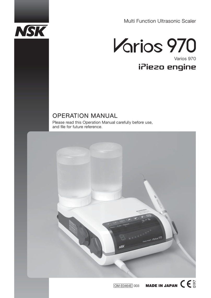
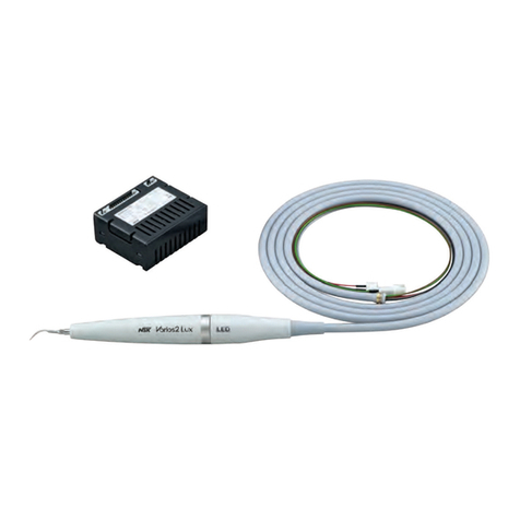
Thank you for purchasing Varios BUILT-IN MODULE (Varios 150 or Varios 150 LUX). This device generates ultrasonic waves intended
for use in dental application such as scaling, root planing, root canal treatment, periodontal and cavity preparation. Read this operation
manual carefully before use, and keep it within user’s reach.
The EU directive 93/42/EEC was applied in the design and production of this medical device.
SAFETY CAUTIONS
Indications of Hazardous Conditions
WARNING
Classification Degree of danger or damage and seriousness
CAUTION
NOTICE
Explains an instruction where bodily injury or damage to device may occur.
Explains an instruction where possibility for minor to medium bodily injury
or damage to device may exist.
Explains an instruction that should be observed for safety reasons.
•
Do not give a strong impact to the handpiece, nor drop onto a hard surface. This could result in electric shock.
• Do not touch the handpiece backend, where electrical connections are made to the cord. It might
result in electrical shock.
• Do not disassemble or alter the handpiece.
• Keep out from patients with cardiac pacemakers.
• Keep out from explosive substances and flammable materials. Do not use for patients
anaesthetized laughter gas especially.
• The device is for professional use only.
• Place the most priority of the patient's safety.
• Check the vibration outside the patient's oral cavity before use. If any abnormalities are found, stop
using immediately and contact your dealer.
• Do not exceed recommended power range for the tip, because it may damage tooth plane and tips.
• The factory-set wiring allows only the Scaling. Connect the optional switch as shown below and
choose the desired mode out of 3 by this switch. Optional switch : Part Number U387-260
• Always use with pouring enough water, or it may damage tooth plane and overheat the handpiece.
• Do not hit ceramic prosthesis during scaling with the tip, because it may damage tips.
• Do not hit metal or porcelain crown except removing them. Tips could break and walk out.
• Do not sharpen and bend the tip. Tips may damage and could not generate enough vibration
during scaling.
• Do not touch the tip on the gums, mucous membranes, or skin directly. There is concern of an
injury or a burn.
• The tip will wear down. If using worn tip makes power down, replace the tip.
• Be sure to firmly mount the tip with provided wrench, or the tip could not generate enough
vibration.
• Check if the dust sticks on the screw of the tip before use and clean it, because tips could not
generate enough vibration
• Be sure to turn on the power switch after mounting the handpiece.
• Do not drop or give an excessive shock.
• Be sure to use NSK tips, because it may not work properly with others.
• Do not sterilize by ultraviolet ray. The handpiece could discolorate.
• Remove the handpiece after the tip is taken off.
• The system functions normally in the environment where the temperature is at 0-40°C (32-104°F)
humidity at 10-85% RH, atomospheric pressure at 500-1060hPa, and no moisture condensation in
the control unit. Use at outside of these limits may cause malfunction.
NOTICE
• During vibration, the handpiece and hadpiece cord may affect computer and LAN cable. Noise
could be heard during operation near the radio receiver.
• Users are responsible for operational control, maintenance and inspection.
• Store the system in the place where the temperature is at -10-60°C (14-140°F), humidity at 10-85%
RH, atmospheric pressure at 500-1060hPa, and the system is not subject to air with dust, sulfur, or
salinity.
1. MOUNTING AND REMOVING TIP
Mount the tip by fastening it lightly by hand. (Fig. 1)
Pass the tip through the hole of the tip wrench, align the four cornered tip’s base and the hole of the tip wrench, and
insert it. Turn the wrench clockwise until it makes several clicks. (Fig. 2) To remove the tip, turn counterclockwise
with the tip wrench. (Fig. 2)
CAUTION
When mounting the tip, always use groves, tip, tip wrench, and handpiece that have been sterilized.
Fasten
Tighten
Tip Wrench
Picture shows Varios 150.Picture shows Varios 150.
2. MOUNTING AND REMOVING HANDPIECE
When mounting the handpiece, align the positioning marks on the handpiece
and the hose, and push it straightly. (Fig. 3)
When removing the handpiece for sterilization, grip the front section and rear
section of the handpiece firmly, and pull straightly to separate. (Fig. 4)
3. OPERATION
(1) Output Range Dial
Provide marking as shown in Fig.5.
4. CARE AND MAINTENANCE
(1) Changing O-ring (Varios 150)
An o-ring is located between handpiece and the handpiece cord
connector. Use a pointed tool to remove, and mount a new o-ring
in the groove. (Fig. 7)
(2) Cleaning of Donut-shape Light (Varios 150 LUX)
Wipe clean the debris off the end face of the optic fibers at the
handpiece with alcohol-wet cotton swab. (Fig. 8)
(3) Changing Lamp (Varios 150 LUX)
Refering to 2. MOUNTING AND REMOVING HANDPIECE, disassemble the handpiece from the handpiece cord.
Remove the cover straightly. Use a precision screwdriver or the like and push out the lamp. Align the lamp pins of a
new lamp with the holes, and push the lamp into. (Fig. 9)
Align the alignment marks on the cover and the handpiece cord, and push the cover to the cord until it clicks. (Fig. 10)
Assemble the handpiece and the handpiece cord.
(2) Setting of Output Power Range
Set the knob to the appropriate range specified on the tip case. (Fig.6)
When tip is in oscillating adjust the knob finely.
WARNING
CAUTION
Do not touch the handpiece backend, where electrical connections
are made to the cord. It might result in electrical shock.
• Be sure to remove the handpiece after tip is removed, because tip
could hurt you.
• When removing the handpiece, grip the plug of the handpiece
cord.
CAUTION
Use within the Power Range. Use above the Power Range could
result in tip failure on damage to the pationt's tooth.
BUILT-IN MODULE
Multi Function Ultrasonic Scaler
OPERATION MANUAL
CAUTION
CAUTION
Do not use a sharp pointed tool to clean the optic end face. In case
the light becomes dim, contact your dealer.
• Do not touch directly or hit the glass part of the new lamp.
• Care needs to be exercised when mounting a new lamp to avoid the o-ring off the groove or being twisted.

E177-050 E177-062
BLACK
RED
BLACK
RED
CN3
U387-015
GENERATOR
AC24V
10%
INPUT
OUTPUT
1
U387-014
DC24V
SOLENOID
VALUE
13
11
9
7
5
3
1
14
12
10
8
6
4
2
HANDPIECE SELECTION
FOOT CONTROL
U387-215
1
2
3
CN3
WATER
BROWN
RED
INPUT AC24V
YELLOW
PURPLE
BLK.
ORG.
GRAY
BLUE
WHITE
BLUE
GRAY
Perio Mode
+12V(pin1)
A(pin3)
B(pin10)
G Mode(scaling)
Perio Mode
Endo Mode
A (pin3)
H
L
L
B(pin10)
H
L
H
H=+12V, L=OPEN
Endo Mode
+12V(pin1)
A(pin3)
B(pin10)
A(pin3)
B(pin10)
+12V(pin1)
Refer to 7.(3) 3 Mode Select Switch
diagram for connection.
U387-014
-
E250-050 E250-062 E250-050 E250-062
--
-
-U387-014
-
G Mode(Scaling)
AC24V
10%
INPUT AC24V
5. STERILIZATION
• Autoclave sterilization is recommended.
• The tip, handpiece, tip wrench and tip holder can be autoclaved.
Autoclave Procedure
Remove the tip after use. (See 1.)
Remove the handpiece from the handpiece cord. (See 2.)
Wipe off dirt and debris on the handpiece with an alcohol-soaked cloth.
Put tip, handpiece, and autoclavable instruments in the sterilization pouch and seal it.
Autoclave it for 20 min. at 121ßC, or 15 min. at 132ßC.
6. TROUBLESHOOTING
When trouble is found, please check the following again before consulting your dealer. If none of these is
applicable or the trouble is not remedied even after action has been taken, a failure of this product is suspected.
Contact your dealer.
7. SCHEMATIC DIAGRAM
(1) Varios 150
CAUTION ON STERILIZATION
•Do not sterilize by ultraviolet ray. The handpiece could discolorate.
•If the sterilizer has a dry process that exceeds 135°C, skip the process.
•If autoclaved with other instruments stained with drag solution, it could strip the plating and make the
surface black.
•Since the bottom shelf of the sterilizer is close to the heat source, it can be too hot in places. Place
instruments in the middle or top shelves.
The device does not
vibrate or the vibration
is weak.
No water comes out or
the water flow is weak.
Water is leaking.
Donut light does not
illuminate.
(Varios 150 LUX)
Problem
-
If the handpiece is detached
from the cord, water will come
out from the end of the cord.
With the cord detached from
the unit, water does not come
out from the unit, or the flow is
weak.
Water is leaking from the
connector between the hose
and the handpiece.
Tip oscillates, but light does
not turn on.
Lamp is correctly and securely
mounted in the socket, but
lamp does not turn on.
Item to check
The tip is not tightened
firmly enough.
The tip is worn.
The vibrator in the
handpiece is defective.
The water is clogged
inside the handpiece.
The water adjustment dial
is closed.
The water filter is clogged.
The o-ring of the
connector between the
hose and the handpiece is
damaged.
The lamp pins are not
correctly engaged in the
socket.
Discontinuity in the
handpiece cord, or failure
in the Built-in Module.
Tighten the tip again until the tip
wrench rotates freely with clicks.
As the tip wears down, vibration will
weaken and stop. Replace it with a new
tip.
Contact your dealer.
Contact your dealer.
Turn the water adjustment dial and set
it to an appropriate water volume.
Contact your dealer.
Replace with a new o-ring as shown in
Fig. 7.
Mount the lamp correctly and securely.
Contact your dealer.
Cause Remedy
G Mode(scaling). The following is the factory-wired
connection. It allows G Mode(scaling) only.
Addition of optional switch allows all three functions : Perio,
Endo, or Scaling by this 3-position toggle.
E177-050 E177-062
U387-015
GENERATOR
CAUTION
When mounting the generator, use the M3 X 0.5 machine screws whose length shall be less than the
thickness of the bracket you use plus 5mm, which is the thickness of the heat sink. If longer than that,
the machine screw might damage the parts inside.
NOTICE
The component indicated in dotted lines is a solenoid value, and is an optional part.
(2) Varios 150 LUX
(3) 3 Mode Select Switch
G Mode(scaling). The following is the factory-wired
connection. It allows G Mode (scaling) only.
Addition of optional switch allows all three functions : Perio,
Endo, or Scaling by this 3-position toggle.
DC24V
SOLENOID
VALUE
INPUT AC24V
AC24V 10%
INPUT AC24V
AC24V 10%
DC24V
SOLENOID
VALUE
Join the connector with leads from the generator terminal board with the one for the optical
from the handpiece cord.
Both connectors have brown and green leads.
CAUTION
When mounting the generator, use the M3 X 0.5 machine screws whose length shall be less than the
thickness of the bracket you use plus 5mm, which is the thickness of the heat sink. If longer than that, the
machine screw might damage the parts inside.
NOTICE
The component indicated in dotted lines is a solenoid value, and is an optional part.
DC24V
SOLENOID
VALUE
Refer to 7.(3) 3 Mode Select Switch
diagram for connection.
1
2
3
4
5
This manual suits for next models
1
Other NSK Media Converter manuals
Popular Media Converter manuals by other brands

Analytic Systems
Analytic Systems VTC605 Series Installation & operation manual
Esu
Esu LokPilot V2.0 user manual

CYP
CYP CV-401V Operation manual
Absolute Process Instruments
Absolute Process Instruments IsoSplitter APD 1393 quick start guide

Siko
Siko WV58MR user manual

Connex
Connex CMx2-TX instruction manual
