B&K P-161-2 User manual

INSTRUCTION
MANUAL
P-161-2
AUDIOMETER
CALIBRATOR

:a
&0
K
INSTRUMENTS.
INC.
INSTRUCTION
MAN
U
AL
P-161-2
AUDIOMETER
CALIBRATOR
February
1975
Defense
Activities
Shippsburg
Cont~ol
Ctr.
Medical
Repair
Branch,Bldg.
406
Mechanicsburg,
PA
17055

E
&.
~
INSTRUMENTS
,
INC
.
I.
II.
TABLE
OF
CONT
EN
TS
GE
NERA
L DE
TA
ILS
TABLE
1.
TABLE
2.
IB
lC
ID
IE
THE
CALIBRATION
SIGNAL
CORRECTION
FOR
THE
ACTUAL
MICROPHONE
SENSITIVITY
MEASUREMENT
OF
2ND
HARMONIC
DISTORTION
THE
2425
VTVM
CALIBRATIN
G THE SY
STE
t'-1
2A
2B
NORMALIZING
THE
2211
AMPLIFIER
GAIN
SETTING
IN
THE
LOUDNESS
BALANCE
CURVE
MODEL
4220
PISTONPHONECALIBRATION
CHECK
III.
OPERATING
INSTRUCTIONS
•
3A
MEASUREMENT
OF
FREQUENCY
AND
OUTPUT
FROM
AN
AUDIOMETER
B &K 2211
AMPLIFIERS
AND
FILTERS
B & K 2425
VTVM
H.P.
5221 B
ELECTRONIC
FREQUENCY
METER
1022
OSCILLATOR
PAGE
1
1
2
3
6
7
7
7
8
11
12
12
12
13
13
E
...
K
INSTRUMENTS
,
INC
.
TABLE
OF
CONTENTS
(Continued)
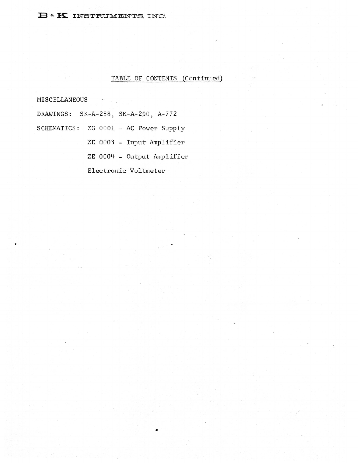
MISCELLANEOUS
DRAWINGS:
SK-A-288, SK-A-290, A-772
SCHEMATICS:
ZG
0001 -
AC
Power
Supply
ZE
0003 -
Input
Amplifier
ZE
OOO~
-
Output
Amplifier
Electronic
Voltmeter
•

13
""
~
INSTRUMENTS.
INC
.
Page
1
I.
GENERAL
DETAILS
lAo
LOUDNESS
BALANCE
DATA
TABLE
1.
Before
the
P-15l-2
Aud
i o
meter
test
stand
can
be
pl
ac
ed
int
o o
pera
t
ion
the
test
channels
must
be
calibrated
to
the
requir
ed
loudness
balance
curve.
The
AN
SI
50
db
hearing
le
ve
l
figures
are
gi
ve
n
bel
ow.
These
levels
TEST
NORMAL
TONE
CALIBRATI
ON
FREQUENCY
LEVEL
125
111.8
250
99.5
500
84.1
750
78.5
1,000
77 ; 2
1,500
78.0
2,000
78.0
3,000
75.6
4,000
74.3
6,000
79.5
8,000
86.8
are
the
desired
acoustical
outputs
of
the
TDH-38
and
39
Earphones.
\I
t
would
be
difficult
~
to
generate
these
sound
pressures
acoustically
with
a
great
degree
of
accuracy
and
so
the
•

:s
& K
INS~RUMENTS
.
INC.
Page
2
r,-
~
.
~
..
..
of.-
.
;s
. "
,f',
..
~
TABLE
2.
P-161-2
is
calib
r
ated
fr
om
an
oscill
a
tor
whicn
is
adjusted
to
gi
ve
an
o
utput
equal
to
that
of
the
microphone.
The
calibration
procedure
includes
a
correction
factor
t o
mo
dify
th
e o
scill
a
tor
output
t o com
pe
ns
a
te
for
t he m
icr
o
ph
one s en
siti
vi
ty
. The f
re
qu
ency
range
of t he "4144 m
icrophone
wh
ic
h
is
us
ed
in
-
the
system
begins
t o
fall
o
ff
at
3 k
Hz
and
an
additional
correction
is
added
to
-
the
loudness
balance
data
to
include
this
factor.
Correcting
the
data
in
Table
1
from
the
B & K
4144
frequency
response
curve
(Fig.
1)
and
incl
udin
g
the
microphone
sensitivity
co
rr
e
ction
we
h
ave
:
ANSI
60
dB
HEARING
LEVEL
CORRE
C
TION
OF
CALIBRATION
LEVELS
/"
Microphone
"
Corrections
Corrected
Cal.
ANSI
C:§
O
cm
-
......
H.L.
r'
r
~
Fre
quen
cy
Level
on
Test
Tone I
Sensit
ivity
" R
esponse
1022
~
\
~-
y
12
5
Hz
~
'0.
+"
\ 0
112.
()
IDS:
'4
,
99.5
.~
IT
n
99.79
$",~
.
2'50
5"00
84.1
7/.S"
1
IT IT
..J.
84.
3'
.,
I.
7
7EO
78.5
'10
(
!!
"
IT
.
78.7
.
?l)~
'a..
1000
77.2
,7
IT
r--...
:,
77.4'
'1. '2.
78.2
~(,.
S IT
~
"
78.
4
".,
1500
2 kHz
78.0
"
iT
II
+.2
78.4
.
'~.
3 kHz
75.6
"10
IT
/
+.5
76.
3
7~.7
4 kHz
74
. 3
",5
IT ( +
1.0
75.5
~
71h'1
6
kH
z
79.5
-,c.5'"
\
IT
i
B)
.,.·.8
80.576-
r
8
kH
z 86.8-
"13
" IT , -
2.0
(A)
/
85
.0
11.
~
.
j\
, \!
~
'--'
\
•
E ok K
INSTRUMENTS
.
INC.
Page
3
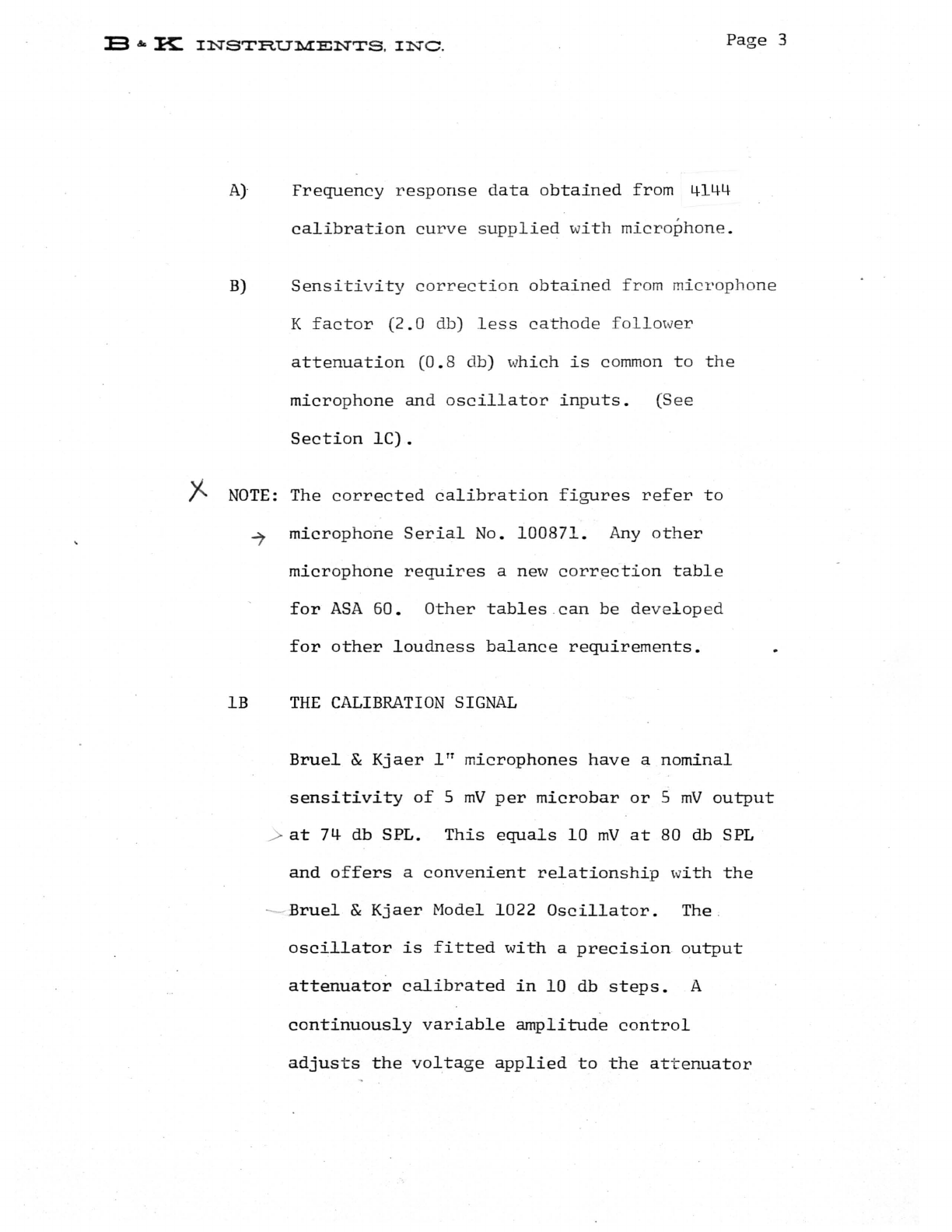
A}
Frequency
response
data
obtained
from
4144
calibration
curve
supplied
w
ith
micr
o
phone.
B)
Sensitivity
cor r ec
ti
on
obtained
fr
om mi
cropho
ne
K
factor
(2.0
db)
less
cath
o
de
fo
llo
w
er
attenuation
(0.
8 db) w
hich
is
co
mmon
to
the
microphone
and
oscillator
inputs.
(See
Section
lC).
)Z
NOTE:
The
corrected
calibration
figures
refer
to
~
microphone
Serial
No.
100871.
Any
other
microphone
requires
a new
correction
table
for
ASA
60.
Other
tables
can
be
developed
for
other
loudness
balance
requirements.
IB
THE
CALIBRATION
SIGNAL
Bruel
&
Kjaer
ITT
microphones
have
a
nominal
sensitivity
of
5
mV
per
microbar
or
5
mV
output
>
at
74
db SPL.
This
equals
10
mV
at
80 db SPL
and
offers
a
convenient
relationship
with
the
--
£ruel
&
Kjaer
Model
1022
Oscillator.
The
oscillator
is
fitted
with
a
precision
output
attenuator
cal
.
ibrated
in
10
db
steps.
A
continuously
variable
amplitude
control
adjusts
the
voltage
applied
to
the
attenuator

E
""
K.
INSTRUMENTS.
INC.
Page
4
x
an
d
the
attenuator
input
is
indicated
on
a
voltmeter
dial
which
is
calibrated
linearly
and
also
in
db. The
meter
scale
has
0 db
at
the
10
%
scale
pos
ition
and
ex
tends
up
scale
-20 db
at
the
f
ull
scale
pso
itio
n .
An
extra
2 db
calibration
above
f
ull
scale
i s
included
to
improve
the
accuracy
of
settin
g
the
o
utput.
When
the
meter
pointer
is
at
0 db (10
%)
and
the
a-
ttenuator
is
set
to
100
mV,
the
actual
output
signal
is
10
mV
thus
the
100
mV
position
of
attenuator
can
be
labelled
80 db SPL.
Similarly
the
othe
r
positions
of
the
attenuator
can
be
marked
from
40
to
100
db
and
intermediate
values
obtained
by
setting
the
output
meter
to
db
values
on
the
meter
scale
and
these
are
added
to
the
attenuator
scale.
As
an
example
an
equivalent
SPL
of
98-db
can
be
set
at
90 db
attenuator
plus
8 db
on
the
meter
scale
or
better
still
80 db
attenuator
and
18
db
meter
scale,
(the
db
scale
can
be
read
more
'
accurately
at
the
higher
scale
readings).
lC
CORRECTION
FOR
THE
ACTUAL
~lICROPHONE
SENSITIVITY
When
a
condenser
microphone
is
connected
into
a
cathode
follower,
the
microphone
open
circuit

E .Ie K
INSTRUMENTS.
INC.
Page
5
sensitivity
is
modified
by
TIvO
effects.
The
first
concerns
the
effect
of
capacity
loading
due
to
the
input
cap
acity
of
the
cathode
follower
ac~ing
as
a
voltage
divider
with
the
micro
p
hone
electrode/diaphragm
capacity.
The
output
is
also
reduced
by
the
attenuation
of
the
cathode
follower.
These
effects
amount
to:
Capacity
loading
effect
0.4
db
Cathode
follower
attenuation
0.8
db
The
calibration
method
used
in
the
P-16l-2
connects
the
oscillator
output
into
the
cathode
follower
via
a
large
coupl~ng
capacitor
thus
the
capacitive
loading
effect
does
not
alter
the
oscillator
level.
The
cathode
follower
does
not
alter
the
oscillator
level.
The
,
cathode
follower
does
att
'
enuate
the
signal
by
8.0
db.
A K
Factor
is
given
for
each
microphone
and
states
the
correction
in
db
which
is
necessary
to
make
the
output
from
the
cathode
follower
equal
to
5
mV/pbar.
If
the
cathode
follower
attenuation
(0.8
db)
is
added
to
the
K
Factor,
the
new K
Factor
refers
to
the
cathode
follower
input
i.e.,
the
same
condition
as
the
test
oscillator.
Avplying
the
K
Factor
to
the
oscillator
output
corrects
for
the
microphone
sensitivity
and
the
E
&.
~
INSTRUMENTS,
INC
.
Page
6
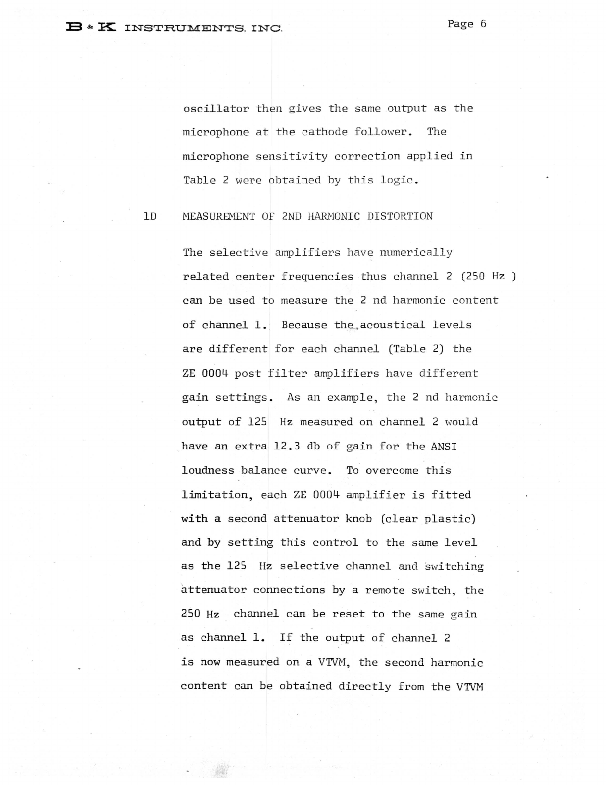
oscillator
then
gives
the
same
output
as
the
microphone
at
the
cathode
follower.
The
microphone
sensitivity
correction
applied
in
Table
2
were
obtai
ned
by
this
logic.
ID
MEASUREMENT
OF
2ND
HARMONIC
DISTORTION
The
selecti
ve
amplifiers
have
numerically
related
center
fre
quencies
thus
channel
2 (250
Hz
)
can
be
used
to
measure
the
2
nd
harmonic
content
of
channell.
Because
the
,
~
ac-oustical
levels
are
different
f
or
each
channel
(Table
2)
the
ZE
0004-
post
filter
amplifiers
have
different
gain
settings.
As
an
example,
the
2
nd
harmonic
output
of
125
Hz
measured
on
channel
2 w
ould
have
an
extra
12.3
db
of
gain
for
the
ANSI
loudness
balance
curve.
To
overcome
this
limitation,
each
ZE
0004-
amplifier
is
fitted
with
a
second
attenuator
knob
(clear
plastic)
and
by
setting
this
control
to
the
same
level
as
the
125
Hz
selective
channel
and
switching
attenuator
connections
bya
remote
switch,
the
250
Hz
channel
can
be
reset
to
the
same
gain
as
channell.
If
the
output
of
channel
2
is
now
measured
on
a
VTVM,
the
second
harmonic
content
can
be
obtained
directly
from
the
VTVM
E
&0
K .
INSTRUMENTS
,
INC
.
Page
7
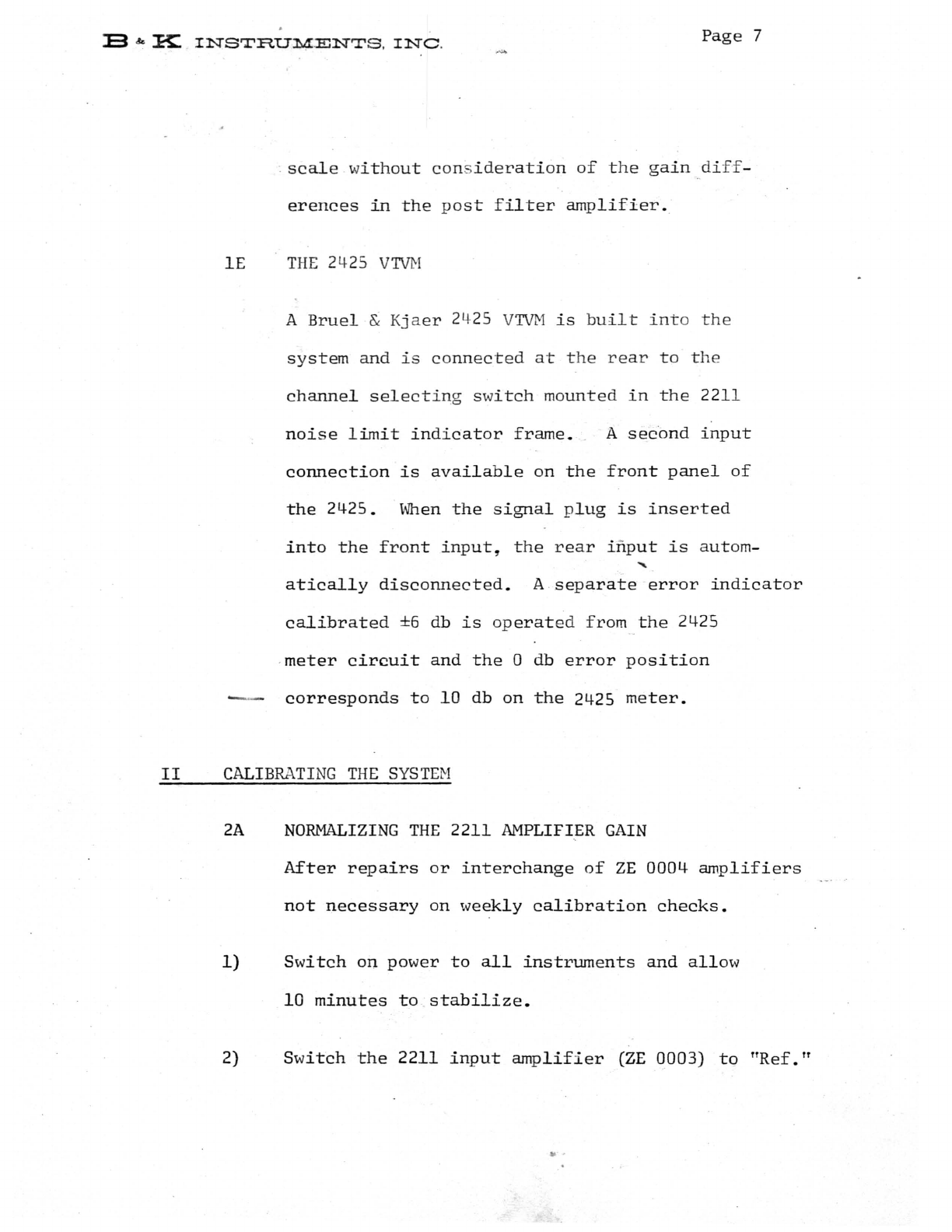
.
scale
wi
t h
out
con
s
ide
r
ati
on
of
the
gain
diff
-
erences
in
the
post
fi
lter
amplifier.
IE
THE
24
25
VTV
t-l
A
Bruel
&
Kjaer
24
25
VTVH
is
built
int
o
the
system
and
is
connected
at
the
rear
to
th
e
channel
selecti
ng
switch
mounted
in
the
2211
noi
s e
limit
indicator
frame.
A
second
input
connection
is
available
on
the
front
panel
of
the
2425.
When
the
signal
plug
is
inserted
into
the
front
input,
the
rear
inp
ut
is
a
ut
om
-
atically
disconnected.
A
separate
error
indicat
or
calibrated
±6
db
is
op
erat
ed
fro
m
the
24
25
·
meter
circuit
and
the
0 db
error
position
----
corresponds
to
10
db
on
the
2425
meter.
II
CALIBRATI
NG
THE SY
STE
M
2A
NORMALIZING
THE
2211
AMPLIFIER
GAIN
After
repairs
or
interchange
of
ZE
0004
amplifiers
not
necessary
on
weekly
calibration
checks.
1)
Switch
on
power
to
all
instruments
and
allow
10
minutes
to
stabilize.
2) Sw
itch
the
2211
input
amplifier
(ZE
0003)
to
ITRef.1f
..
.

13
&.:
~
INS'rRUMENTS
.
INC
.
Page
8
3)
Select
"Fi
lter
inputfT
on
the
2211
monitor
me
ter
-:.,-.
and
adjust
the
ZE
0003
fine
g
ain
control
until
the
monitor
meter
indicates
on
the
lower
red
reference
mark.
4)
Select
pos
iti
on 1 on t he m
onitor
m
eter,
swi
tch
the
125
Hz
chan
n
el
(ZE
0004
Ncr:
1)
to
"Lin.
I I
5)
Turn
t he
blac
k
attenuato
r
knob
to
0 db
and
adjust
the
fine
gain
control
so
that
the
monitor
meter
coincides
w
ith
the
upper
red
reference
mark.
6)
Repeat
for
the
other
11
channels.
7)
Reset
all
filter
switches
to
ITFilter-infT
position
(to
the
left).
THE
AMPLIFIER
GAINS
ARE
NOW
NORMALIZED.
2B
SETTING
IN
THE
LOUDNESS
BALANCE
CURVE
(\veekly
calibration)
1)
Patch
the
1022
oscillator
attenuator
output
into
the
cathode
follower
using
the
JJ2612
adaptor
and
test
cable
supplied.
2)
z
and
adjust
the
output
to
the
required
db
settin
g
using
the
clear
plastic
overlay
on
the
1022
osciJ~ator
output

E
&.
K
INSTRUMENTS,
INC
.
Page
9
control.
The db
setting
is
given
on
the
Table
2
for
a
specific
microphone.
3)
Set
the
2211
input
amplifier
(ZE
0003)
ga
in
control
t o
110
db.
Advance
the
o
utput
sel
ector
to
channel
1
using
the
foot
operated
switch.
5)
Check
the
oscillator
frequency
on
the
counter
and
increase
the
ZE
0004
gain
using
the
black
knob
until
the
error
meter
indicates
o
db.
Use
the
screw
adjustment
for
the
final
correction.
6)
Switch
to
channel
2,
set
the
ZE
0004
for
that
channel
to
TTLin
TT
•
7)
Select
IIHarmonic
distortion
TT
on
the
toggle
switch
(lower
left
bay)
and
adjust
the
clear
plastic
gain
control
on
ZE
0004
ch~nel
2
until
the
error
meter
is
approximately
at
o
db.
The
nearest
attenuator
setting
is
adequate.
Do
not
change
the
screw
adjustment
of
channel
2 -
ZE
0004.
8)
Return
channel
2
ZE
0004
to
IIFilter
ll
and
turn
the
harmonic
distortion
switch
to
IINormal
TT
•
Set
the
oscillator
to
250
Hz
,
set
the
oscillator

13
& K
INSTRUMENTS,
INC.
Page
10
output
to
the
-250
Hz
sound
pressure
level
on
the
corrected
loudness
balance
curve
(Table
2)
and
adjust
the
black
attenuator
knob
on
the
ZE
0004
(channel
2)
until
the
error
meter
reads
0
db.
Use
the
screw
adjustment
i f
necessary.
9)
Repeat
step
7
for
channel
3.
,
10)
Repeat
step
8
for
chann
el 3
using
500
Hz
and
the
appropriate
oscillator
output.
11)
Channel
5
is
the
second
harmonic
of
channel
3
and
the
procedure
for
channel
3
and
higher
channel
numbers
is
slightly
different.
Proceed
as
below:
12)
Select
channelS
with
the
os
.
cillator
set
at
500
~
Hz.
13)
Set
channelS
to
ITLlrf.1T
Select
harmonic
distortion
on
the
toggle
switch
and
adjust
the
clear
-----------..
plastic
gain
control
of
channel
5
until
the
error
meter
indicates
approximately
0
db.
Do
not
change
the
screw
adjustment.
14)
Swi
tch
Channel
5
to
ITFil
ter
IT
•
E & K
INSTRUMENTS
,
INC,
Page
11
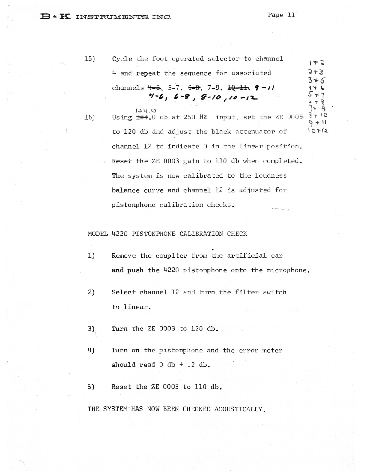
15)
1 6)
Cycle
the
fo
ot
oper
ated
selector
to
c
ha
nnel
4
and
repeat
the
sequence
for
associated
channels.&.!-e-,
5-7,
6-'&,
7-9,
19:
11.
'-II
':1-",
,-g-~
g-ID//#-/"2...
J.}.4.C
Usi
ng
~.O
db
at
250 Hz
in
put,
set
the
7.E
OOO~
to
120
db
and
ad
ju
st
the
black
at
tenuator
of
channel
12
to
in
d
icate
0
in
the
linea
r
position.
Reset
the
ZE
0003
gain
to
110
db w
hen
completed.
The
system
is
now
calibrated
to
the
loudne
s s
balance
curve
and
channel
12
is
adjuste
d
for
pistonphone
calibration
checks.
~
-
.
MODEL
4220
PISTONPHONE
CALI
BRA
TION
CHECK
1)
Remove
the
couplter
from
the
artificial
ear
\"\'"~
';)"3
3'1-
$'
't
'+-
fo
S
't'
1
l.
'IT
~
1'1-
I
~
~,.
10
~TII
\ 0 ,.
f~
and
push
the
4220
pistonphone
onto
the
micro
p
hone.
2)
Select
channel
12
and
turn
the
filter
switch
to
linear.
3)
Turn
the
ZE
0003
to
120
db.
4)
Turn
on
the
p
istonphone
and
th
e
error
meter
should
read
0 db ±
.2
db.
5)
Reset
the
ZE
0003
to
110
db.
THE
SYSTEM
·HAS
NOW
BEEN
CHECKED
ACOUSTICALLY.

E
""
~
INS'rRUMENTS.
INC.
Page
12
2C
METER
PROTECTION
All
meter
circ
uits
in
th
e
P-161-2
audiometer
calibrat
or
are
e
lectrically
protected
and
ar
e
not
damaged by
off
scale
meter
indications
.
III
OPERATING
INSTRUCTIONS
3A
MEASUREHENT
OF
FREQUENCY
AN
D
OUTPUT
FROM
AN
AUDIOMETER
1)
Turn
the
system
on
and
allow
10
minutes
to
stabili
ze
.
Set
the
various
cont
ro
ls
as
listed
below:
B & K 2211
AMP
LI
FI
ER
S
AND
FI
LTERS
ZE
0003
ZE
0001+
Normal/Distortion
(switch)
B & K
2425
VTVH
Range
Meter
Switch
110
db
position
"Filter-in
positionlT
Gain
as
set
during
calibration
ITNormal
lT
position
(VU
Damping
Meter
function)
NO
PLUG
SHOULD
BE
LEFT
IN
THE
FRONT
INPUT
> E
&.:B:
IN
STRUM
EN
TS
,
INC
.
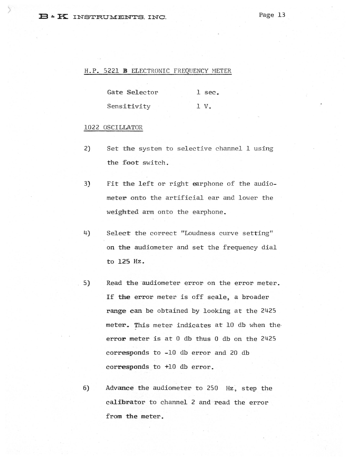
H.P.
5221 B E
LECT
R
ON
IC
FREQ
UENCY
METER
Gate
Se
lector
Sensi
t
ivity
1022
OS
CIL
LA
TOR
1
sec.
1
V.
Page
13
2)
Set
th
e
system
to
selective
channe
l 1
using
the
f o
ot
switch.
3)
Fit
th
e
left
or
right
earphone
of
the
audio-
mete
r o
nto
the
artificial
ear
and
lo
wer
the
weighted
arm
onto
the
earphone.
4)
Sele
ct
the
correct
TTLoudness
curve
setting
TT
on
th
e
audiometer
and
set
the
frequency
dial
to
12
5
Hz.
5)
Read
th
e
audiometer
error
on
the
error
meter.
If
the
error
meter
is
off
scale,
a
broader
range
can
be
obtained
by
looking
at
the
2425
mete
r.
This
meter
indicates
at
10
db when
the
·
error
meter
is
at
0 db
thus
0 db
on
the
2425
corr
es
ponds
to
-10
db
error
and
20
db
corresponds
to
+10
db
error.
6)
Advance
the
audiometer
to
250
Hz
,
step
the
calibrator
to
channel
2
and
read
the
error
from
the
meter.
13
&.
~
INSTRU::M:ENTS.
INC
.
Page
14
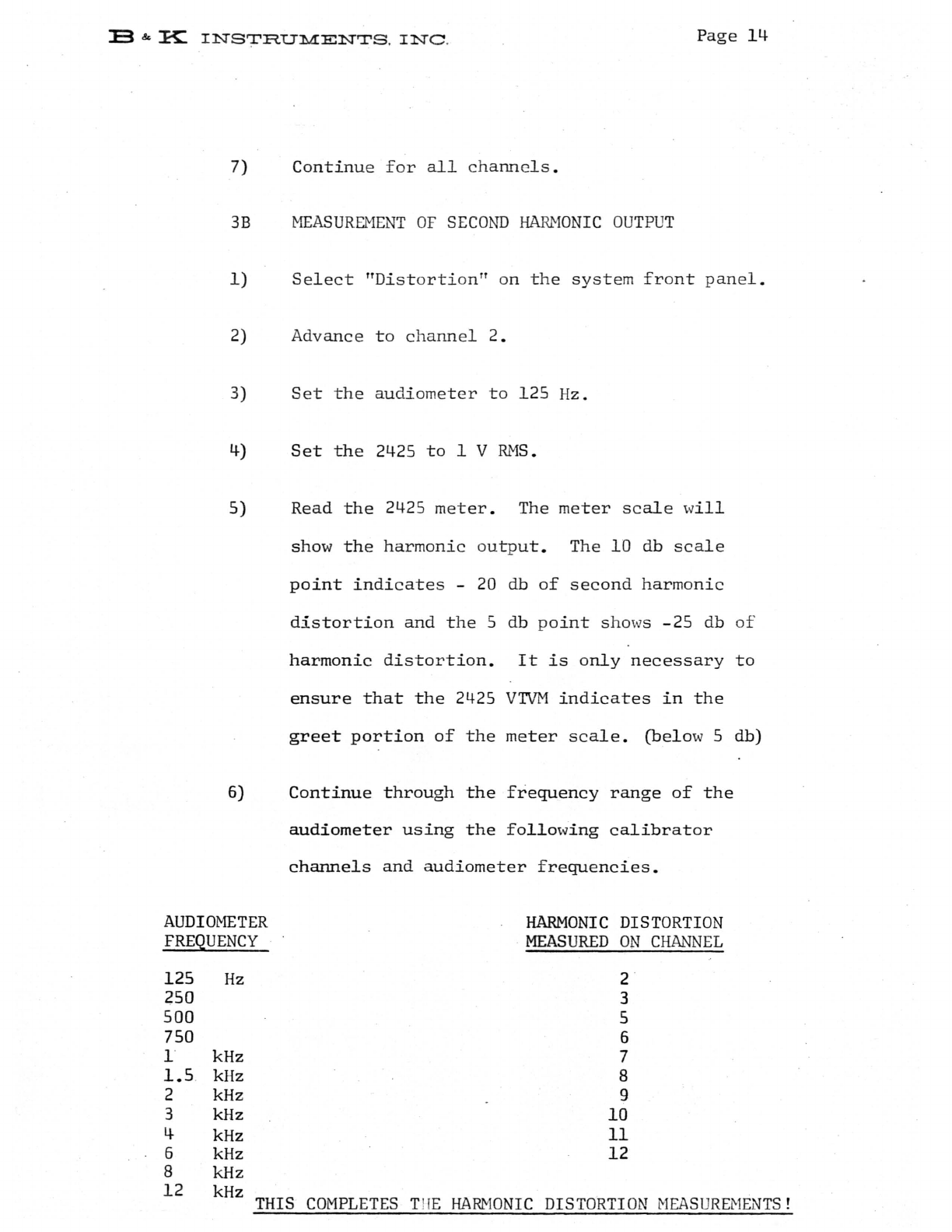
7)
Continu
e
for
all
channels
.
3B
MEASUREMENT
OF
SECOND
HARMONI
C
OUTPUT
1)
Select
"Distorti
o
n"
on
the
system
front
panel
.
2)
Advance
to
channel
2.
3)
Set
the
audiometer
to
125
Hz.
4)
Set
the
2425
to
1 V
RMS.
5) Read
the
2425
meter.
The
meter
scale
w
ill
show
the
harmonic
outpu
t.
The
10
db
scale
point
indicates
-20 db
of
second
harmonic
distortion
and
the
5 db
po
int
sho
ws
-25
db
of
harmonic
distortion.
It
is
only
necessary
to
ensure
that
the
2425
VTVM
indicates
in
the
greet
portion
of
the
meter
scale.
(below
5 db)
6)
Continue
through
the
frequency
range
of
the
audiometer
using
the
following
calibrator
channels
and
audiometer
frequencies.
AUDIOMETER
FREQUENCY
HARMONIC
DISTORTION
MEASURED
ON
CHANNEL
125
250
500
750
1
1.5
2
3
4
6
8
12
Hz
kHz
kHz
kHz
kHz
kHz
kHz
kHz
kHz
2
3
5
6
7
8
9
10
11
12
THIS
COMPLETES
THE
HARMONIC
DISTORTION
NEA
S
URE~lEN
TS!

lJJ
oct.IW
WIld
p,i
5S
f
Il
ters
lIS
0201-
Z5
0235
FR.E.Q
UE
;
CY
LlO
!-2-3 C\o\-2-3 R
IOI
!R.\02.
RI
O~
I I
! R
\0
4-
i
I f
I
~5
S.H
-
0·2-
--
300
\(
.fL
!
.300
KIt
I
2.50
4-
.H
O·
I --
II
I'
75
0 I1·
2SH
0 -
035
--"
\I
,
\0
00
i -1
I • H -
02.5
5
00
KfL I -\
50
\
(./L
:3.-00
1e(
.Q
I
O
.
G:,~
H I
15(,
"0
'017
300
K-
'l:
5CO/.(.n..
II
"
20c0
0
·5
H
'0
12..
.1
II
\1 "
3
000
.315 H -OC9
1\
tI
1\
~
40
00
i °
25
H
-0
06
3 •
.,
II II -
6
000
'16
H '
0043
-II II "
190
00
'125
H ·
C032.
"
..
• -
I
120
00
,
~08
H
'00
2.2
1\
1\
~
,
~
O
2..H
·
o~
--
..300
1'
f2..
"
CPS
!
HEN
RIES
I
UFD
I
COtw'IPO
t--.\
ENT
VAL\J~S
SP(CI
AL
F
rLl
E'Rs,,-
'P
IC;\A
AUD
IOMETER
CAL
I
BRA
TO
£..
•
S!(28B
23
Al)&65

;
. I
!
f
I .
"
I
I
i"
,
!
.1
I
I
I
~
I
Table of contents
Other B&K Test Equipment manuals


Popular Test Equipment manuals by other brands


Keysight Technologies
Keysight Technologies InfiniiVision 1000 X-Series Service guide

Parker
Parker icountBS user manual

Rubarth Apparate
Rubarth Apparate RUMED 4001 Operating and maintenance instructions

Komshine
Komshine KFL-11P Instructions for use

Keysight Technologies
Keysight Technologies InfiniiVision 4000 X Series Programmer's guide

High Voltage
High Voltage VLF-CM Series Safety, Operation, and Procedure Instructions


