TD-8-035-IM1 Iss. D
Gas cylinders feeding PNEUCHANGE units must be tted with suitable regulators to reduce the supply
pressure to less than 6.9bar [100psi]. The range of NTC regulators are recommended.
PNEUCHANGE is tted with 3/8" BSPP male hose coupler ports to which standard UK regulator
hosetails can be tted. Hosetails for 6.4mm [1/4"] ID, hose are supplied. Other sizes can be purchased
separately. For best results CFILT lters should be tted to the inlet ports to prevent gas borne
particles fouling internal valves. See page 5.
Hoses should be secured with "Jubilee"™ or other suitable clips. Adaptors to connect PNEUCHANGE to
alternative pipework are listed on page 5.
The 3/8" BSPP port connectors are designed to seal between the faces of the convex hose coupler and
the concave port without sealant. The use of sealant paste or PTFE tape is NOT necessary. Connect
supply pipework to inlet ports.
Clamp hose to hosetail using suitable hose clip.
DO NOT USE SEALING PASTE OR PTFE TAPE
Locate tting into port.
Tighten nut until gas tight-DO NOT OVER TIGHTEN
TO PREVENT INTERNAL DAMAGE DO NOT ALLOW
PORT TO ROTATE WHEN TIGHTENING HOSE COUPLER
4
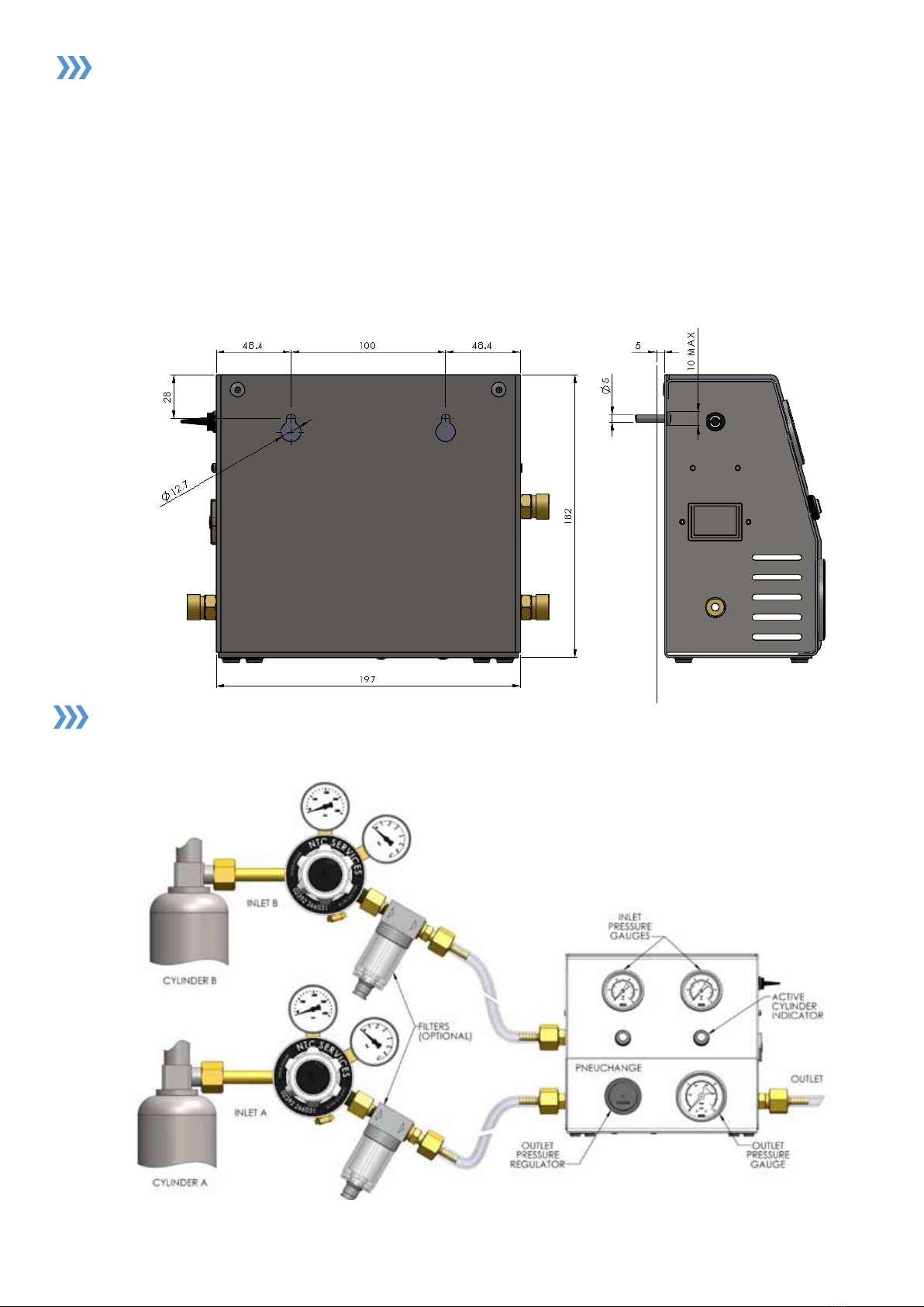
Fig.3
OPERATION
Starting with two full cylinders regulated down to between 3.1 to 6.9bar [45 to 100psi], ensure
PNEUCHANGE inlet gauges indicate cylinder regulator outlet pressures. Set the PNEUCHANGE outlet
pressure to that required by the equipment (Incubator etc.) being served. This will be found in the
manufacturer's instructions. The unit will feed from the rst connected cylinder until this exhausts then
the unit will automatically feed from the other cylinder.
On replacing the empty cylinder the unit will continue to feed from the currently active cylinder until
this is exhausted and the sequence will then repeat. No manual resetting is required.
ALARM FACILITY
PNEUCHANGE is tted with an audible changeover alarm operated from a 9 volt PP3 type battery or
equivalent. It is accessed via the battery drawer on the right hand side of the unit.
The alarm switch has two reset positions, one of which is constantly active.
• To use the alarm facility set the alarm switch to the inactive reset position.
• When cylinder changeover occurs, the alarm will sound.
• Switching to the opposite reset position will silence the alarm and set the unit for the next
changeover alarm signal.
• Replace the empty cylinder as detailed under operation as shown above.
N.B. Alarm may sound prior to changeover
Setting the alarm to the ‘off’ position will remove the audible alarm facility, but PNEUCHANGE will
continue to change cylinders as required.
The PNEUCHANGE alarm system detects differential pressure when Inlet B is active. The pressure
switch requires minimum 1.4bar [20psi] rising pressure on side B to switch state before detecting
1.4bar [20psi] falling pressure as cylinder empties. THE ALARM WILL NOT FUNCTION IF THE UNIT
INLET PRESSURE IS BELOW 1.7bar [25psi]. When side B is active and supplied above 1.7bar
[25psi] with the alarm switch in the upper reset position, the alarm will remain silent until the supply
pressure to port B falls to below 1.7bar [25psi] at which point the audible alarm will sound.