manuals.online logo
Brands
  1. Home
  2. •
  3. Brands
  4. •
  5. Ntron
  6. •
  7. Media Converter
  8. •
  9. Ntron SER-485-1C User manual

Ntron SER-485-1C User manual

SER-485-IC_0710 R2
N-Tron Corp.
820 S. University Blvd. Suite 4E, Mobile, AL 36609
PH: 251-342-2164 · FAX: 251-342-6353
2
2.
.
I
In
nf
fo
or
rm
ma
at
ti
io
on
n
–
–
U
UL
L
C
Cl
la
as
ss
s
1
1
D
Di
iv
v
2
2
1. Power, input /output (I/O) wiring must be in
accordance with Class 1 Division 2 wiring methods
[Article 501.10(B) of the National Electric code,
NFPA70] and in accordance with the local authority
having jurisdiction.
2. Maximum ambient air temperature 80°
3. WARNING –EXPLOSION HAZARD:
SUBSTITUTION OF COMPONENTS MAY IMPAIR
SUITABLITY FOR CLASS 1, DIVISION 2.
4. WARNING –EXPLOSION HAZARD: WHEN IN
HAZARDOUS LOCATIONS, TURNING OFF
POWER BEFORE REPLACING OR WIRING
MODULES
5. WARNING –EXPLOSION HAZARD: DO NOT
DISCONNECT EQUIPMENT UNLESS POWER HAS
BEEN SWITCHED OFF OR THE AREA IS KNOWN
TO BE NON-HAZARDOUS.
6. WARNING –THIS APPARATUS IS SUITABLE FOR
USE IN CLASS 1 DIVISION 2, GROUPS A, B, C,
AND D, OR UNCLASSIFIED AREAS.
1
1.
.
C
Ch
he
ec
ck
k
f
fo
or
r
R
Re
eq
qu
ui
ir
re
ed
d
H
Ha
ar
rd
dw
wa
ar
re
e
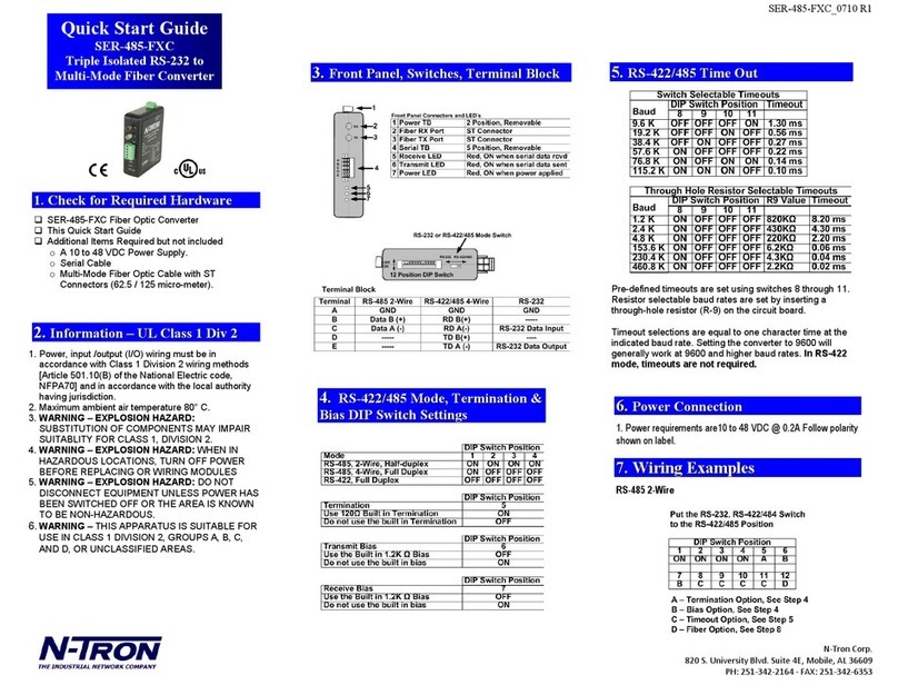
SER-485-IC Serial Converter
This Quick Start Guide
Additional Items Required but not included
oA 10 to 48 VDC Power Supply, 0.2A.
oRS-232 cable. The converter is a DCE device.
oRS-422/485 Cable.
Put
Quick Start Guide
SER-485-IC
Triple Isolated RS-232 to
RS-422/485 Converter
4
4.
.
I
In
nf
fo
or
rm
ma
at
ti
io
on
n
-
-
D
DI
IP
P
S
Sw
wi
it
tc
ch
h
Communications Mode
1
2
3
4
RS-485
ON
ON
ON
ON
2-Wire
Half Duplex
RS-485
ON
OFF
OFF
OFF
4-Wire
Full Duplex
RS-422
OFF
OFF
OFF
OFF
Full
Duplex
Termination Resistor
5
Use the 120Ω
ON
Built in Termination
Use External
OFF
or no termination
Transmit Bias
6
Use the 1.2KΩ
Transmit
OFF
Bias Resistor
Use External or no
ON
Transmit Bias Resistor
Receive Bias
7
Use the 1.2KΩ Receive
OFF
Bias Resistor
Use External or no
ON
Transmit Bias Resistor
3
3.
.
I
In
nf
fo
or
rm
ma
at
ti
io
on
n
–
–
F
Fr
ro
on
nt
t
P
Pa
an
ne
el
l
Front Panel
1
Power TB
2 Position, Removable
2
RD LED
Red, Flashes when RS-422/485
Data Received
3
DB9 Female
RS-232 (Wired DCE)
4
422/485 TB
5 Position, Removable
5
TD LED
Red Flashes when RS-422/485
Data Transmitted
6
Power LED
Red, ON When Power Applied
7
Dip Switch
12 Position
DB9 Female Pin out (DCE)
Pin
Signal
Direction
1
Receive Line Signal Detector (DCD)
---
2
Receive Data (RD)
OUTPUT
3
Transmit Data (TD)
INPUT
4
DTE Ready (DTR)
---
5
Signal Ground (SG)
---
6
DCE Ready (DSR)
---
7
Request to Send (RTS)
---
8
Clear to Send (CTS)
---
9
Ring Indicator (RI)
---
Note: Pin 1, Pin 4, and Pin 6 are tied together internally.
Pin 7and Pin 8 are tied together internally.
RS-422/485 Terminal Block
Terminal
RS-485 2-Wire
RS-422/485 4-Wire
A
GND
GND
B
Data B(+)
RDB(+)
C
Data A(-)
RDA(-)
D
---
TDB(+)
E
---
TDA(-)
SER-485-IC_0710 R2
N-Tron Corp.
820 S. University Blvd. Suite 4E, Mobile, AL 36609
PH: 251-342-2164 · FAX: 251-342-6353
6
6.
.
P
Po
ow
we
er
r
C
Co
on
nn
ne
ec
ct
ti
io
on
n
Power Requirements:
10 –48 VDC @ 0.2A
7
7.
.
R
RS
S-
-2
23
32
2
C
Co
on
nn
ne
ec
ct
ti
io
on
n
1. DB9 F is DCE, Pin 2(RD) is the converter’s RS-232
Data output. Pin 3 (TD) is the converter’s RS-232
Data input.
2. Pins 1, 4, and 6 (DCD, DTR, and DSR) are tied
together inside the converter.
3. Pins 7 and 8 (RTS and CTS) are tied together
inside the converter.
8
8.
.
W
Wi
ir
ri
in
ng
g
E
Ex
xa
am
mp
pl
le
es
s
Two Wire RS-485
9
9.
.
L
Lo
oo
op
p
B
Ba
ac
ck
k
T
Te
es
st
t
/
/
T
Tr
ro
ou
ub
bl
le
es
sh
ho
oo
ot
ti
in
ng
g
Configure for RS-485 Four wire, 9600 baud
Jumper terminals B to D and C to E
Connect a PC to the RS-232 port (see Step 7).
Using hyper terminal or similar program, connect to
the appropriate COM port (remember to set the
baud rate to 9600).Turn off hyper terminal local
echo
Transmit data. The same data should be returned.
LED Indicators: Power is ON when power is applied.
TD flashes when RS-422/485 data is sent. RD
flashes when RS-422/485 Data is received.
RS-422/ Four Wire RS-485
5
5.
.
R
RS
S-
-4
42
22
2/
/4
48
85
5
T
Ti
im
me
e
O
Ou
ut
t
Switch Selectable
Baud
Timeout
(Kbps)
8
9
10
11
12
(ms)
2.4
ON
OFF
OFF
OFF
OFF
4.37
4.8
OFF
ON
OFF
OFF
OFF
2.03
9.6
OFF
OFF
ON
OFF
OFF
1.02
19.2
OFF
OFF
OFF
ON
OFF
0.57
38.4
OFF
OFF
OFF
OFF
ON
0.27
Resistor Selectable
Baud
R-11
Timeout
(Kbps)
8 through 12
Value
(ms)
1.2
OFF
820 KΩ
8.32
57.6
OFF
16 KΩ
0.16
115.2
OFF
8.2 KΩ
0.08
Pre-defined timeouts are set using switches 8 through 12.
Resistor selectable baud rates are set by inserting a through
hole resistor (R-11) on the circuit board.
Timeout selections are equal to one character time at the
indicated baud rate. Setting the converter to 9600 will
generally work at 9600 and higher baud rates. In RS-422
mode, timeouts are not required.

Other Ntron Media Converter manuals

Ntron 302MC-SC User manual

Ntron

Ntron 302MC-SC User manual

Ntron 1002MC-LX-YY Installation and operating instructions

Ntron

Ntron 1002MC-LX-YY Installation and operating instructions

Ntron 202MC-SC User manual

Ntron

Ntron 202MC-SC User manual

Ntron 102PC-SE Installation and operating instructions

Ntron

Ntron 102PC-SE Installation and operating instructions

Ntron 102MC Installation and operating instructions

Ntron

Ntron 102MC Installation and operating instructions

Ntron SER-485-FXC User manual

Ntron

Ntron SER-485-FXC User manual

Ntron 202MC User manual

Ntron

Ntron 202MC User manual
Popular Media Converter manuals by other brands

axing HKI 41-34 Operation instructions

axing

axing HKI 41-34 Operation instructions

Ideal Power Stabiliti Series quick start guide

Ideal Power

Ideal Power Stabiliti Series quick start guide

ABB ACS880-1607LC Hardware manual

ABB

ABB ACS880-1607LC Hardware manual

Vacon CXL user manual

Vacon

Vacon CXL user manual

Ground Zero GZCV 2.0HL owner's manual

Ground Zero

Ground Zero GZCV 2.0HL owner's manual

Alphi IP-48ADM16TH Reference manual

Alphi

Alphi IP-48ADM16TH Reference manual

EEG EN537 Lexi user guide

EEG

EEG EN537 Lexi user guide

Prolon PL-485-USB quick start guide

Prolon

Prolon PL-485-USB quick start guide

exaSound e68 owner's manual

exaSound

exaSound e68 owner's manual

Polytron OPM-LNB circ 032 manual

Polytron

Polytron OPM-LNB circ 032 manual

Kramer KDS-EN6 user manual

Kramer

Kramer KDS-EN6 user manual

Electro Industries FiberCom user manual

Electro Industries

Electro Industries FiberCom user manual

Littfinski Daten Technik S-DEC-4-MM-B Assembly instruction

Littfinski Daten Technik

Littfinski Daten Technik S-DEC-4-MM-B Assembly instruction

M&C CG Series instruction manual

M&C

M&C CG Series instruction manual

Whyte WT51-10WB instruction manual

Whyte

Whyte WT51-10WB instruction manual

Harmonic Electra 1000 installation guide

Harmonic

Harmonic Electra 1000 installation guide

Kramer VP-704SC user manual

Kramer

Kramer VP-704SC user manual

SeeEyes SC-MAC02 user manual

SeeEyes

SeeEyes SC-MAC02 user manual

manuals.online logo
manuals.online logoBrands
  • About & Mission
  • Contact us
  • Privacy Policy
  • Terms and Conditions

Copyright 2025 Manuals.Online. All Rights Reserved.