NTS PD2410 User manual

J. Specifications
Transmitter:
Operating Frequency Band 2.403GHz~2.478GHz
Maximum Transmit Power 100mW
Modulation 16QAM/QPSK/BPSK
Video Input Level 1V p-p @75 ohm
Audio Input Level 1V p-p @600 ohm (STEREO)
Antenna Omni-directional
IR remote IR output 940nm with ON/OFFkeying
Power consumption 1.9W
Power supply 12V/1A
Dimension 76mm*73mm*24mm
Weight 82g
Receiver:
Operating Frequency Band 2.403GHz~2.478GHz
Receiver Sensitivity -85dBm min.
Video Output Level 1±0.2V p-p @75 ohm
Audio Output Level 1±0.2V p-p @600 ohm (STEREO)
Antenna Omni-directional
IR remote IR Input 940nm with ON/OFFkeying
Power consumption 1.9W
Power supply 12V/1A
Dimension 76mm*73mm*24mm
Weight 82g
System:
Transmission channels 26 channels auto selection
Video bit rate up to12Mbps
Random ID code up to 4 million sets
Video resolution 720 x 480 @ 30 fps (NTSC) or 768 x 576 @25 fps (PAL)
Operational range up to 800 meters (line of sight and open site)
Remote control (Optional) range up to 500 meters (line of sight and open
site)
All specification subject to change without notice
-11-
2.4GHz Digital
Transmission system
Manual with IR
extender(option)
V1.0

-1-
-10-
Important-Safety Precautions
To prevent fire or shock hazard, do not expose this device to rain or moisture.
Does not use near a bathtub, washbowl, kitchen sink, or laundrytub,
in a wet basement, or near a swimming pool.
■To avoid electrical shock, do not open this device.
■This device should be operated to use only the power supply included with it
or provided as an accessory.
■Do not overload wall outlets and extension cords as this can result in the risk
of fire or electrical shock.
■Do not attempt to service this device yourself. Refer servicing to qualified
personnel only.
■Reorient or relocate the receivingantenna.
■Increase the separation between the equipment and receiver.
■Connect the equipment into an outlet on a circuit different from that to which the
receiver is connected.
■Consult the dealer or an experienced radio/TV technician for help.
■Note:
This equipment has been tested and found to comply with Part 15 of the FCC
Rules, or R&TTE CE directive. These limits are designed to provide reasonable
protection against harmful interference in a residential installation. This equipment
generates, uses and can radiate radio frequency energy, if not installed and used
in accordance with the instruction, it may cause harmful interference to radio
communications. However, there is no guarantee that interference will notoccur
in a particular installation. If this equipment does cause harmful interference to
radio or television reception, which can be determined by turning the equipment
off and on, the user is encouraged to try to correct the interference by one or more
of the following measures:
H.UseNotes
1.
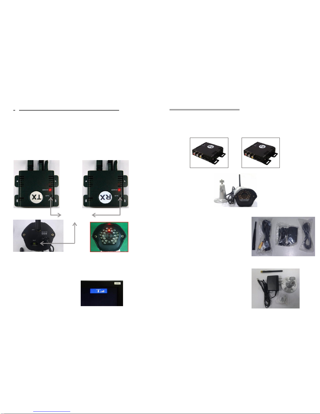
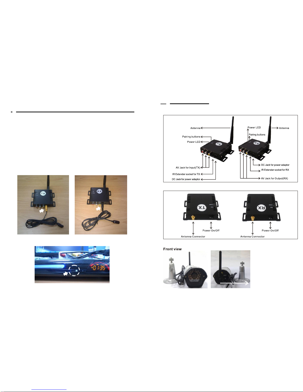
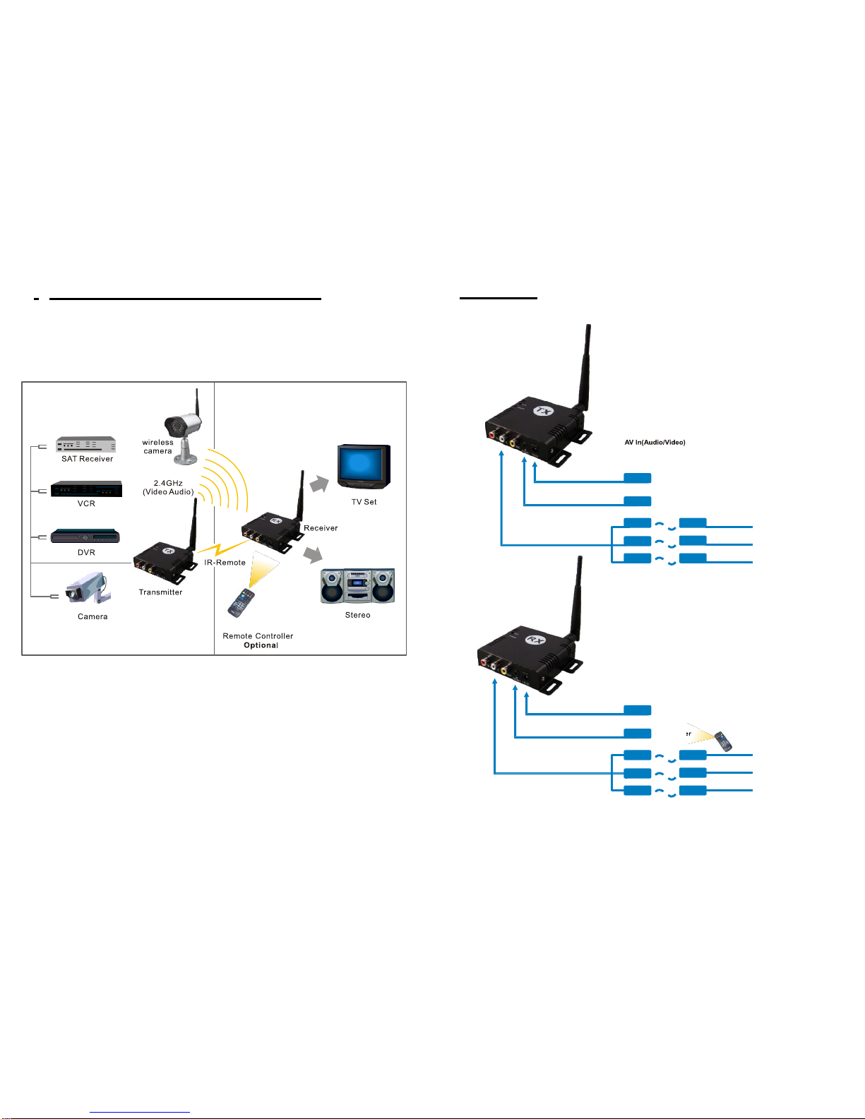
Besurethetransmitter andthe receiverwereconnectedtotheequipment
correctly
(e.g. Connect the transmitter to thecamera, and the receiver to the TV or
DVR).
2.
WhenDCplug ispulledoutfrom transmitter orreceiver orwireless
camera,
it needs to wait for a few seconds to insert it again.
3.
Adjust antenna to decrease interference. (vertical or horizontal)
4.
In most situations, one pair has a better distance up to 800 meter (open site).
When two pairs ormore used atthesame time, can automatically jump to
different channels, butthe distance between pairs, preferably greater than2meters far.
5. If there are some reasons cause the devise stop, you can try toturn off the power
thenonagainandmake thedevisere-link(re-pairing)
6.
Itissuggested tohave 10pairs mostly operated insame location, but the
pairing
can not be at the same time.
7.
When use IRextender (option), itisnormal when response slow in the receiver
side (RX) byremote control, please don't clicktheremote control keys too
quick.
I.Troubleshooting
Notice: The change or modifications not expressly approved by the party
responsible for compliance could void the user's authority to operate
the equipment.
IMPORTANT NOTE: To comply with the FCC RF exposure compliance requirements,
no change to the antenna or the device is permitted. Any
change to the antenna or the device could result in the
device exceeding the RF exposure requirement and void
user's authority to operate the device.
Problems
Possible Solution
Monitor(RX) shows
“No Video Signal”
Wireless
Camera
CCD
bad,
or
no
video
input
from
TX(wired
camera,
DVD
power
off
or
stolen,
cable
disconnected
or
damaged),
please
check
and
make
it
right
Monitor(RX) shows
“No Signal”
Wireless
camera
or
TX
power
off;
wireless
camera
or
TX
vs
RX
distance
is
too
long,
so
that
transmission
signal
is
weak,
please
check
and
make
it
right
No picture or sound
Check all cable connections
Make sure power plugs are pushed all the way in
Check power switches on the remote TV or DVR and
Video source (Camera, Camcorder, etc.)
Check if the POWER LED of the transmitter/digital wireless
camera and receiver is lighting or not? Their LINK LED should be lit
If Their LINK LED should not be lit, you must re-pair their
codes following the D. instruction of the manual
Interference:
picture or audio
Adjust receiver and transmitter/digital wireless camera antenna
orientation
Try to place transmitter/digital wireless camera and receiver in a
more close-in location
If using a microwave oven, turn it off.
Remove microwave oven or wireless router from the path between
transmitter/digital wireless camera and receiver

-9-
-2-
G.Pairing the transmitter and receiver
When you get the transmitter/digital wireless cameras or receiver, you must pair
them before use it, following the instructions asbelow:
1.Power on the transmitter and receiver by inserting the power adaptor jack.
2.Press the pair button of transmitter or receiver and not release until the power
LED begin to flash, then release the pairbutton.
3. They will enter into the pairing state and automatically link to each other
by ID code after step 2finished.
4. Please don't turn off their power switch during the paring status.
5. When pairing successfully, the power LED for both will be lit directly (not
flash)
.What is inside the Box?
Please check the following items inside the box for 2.4Ghz Digital Wireless
camera, or Digital AV sender with IR extender (option), and contact your dealer
if anything is missing:
1. Products body
and
Receiver x1 Transmitter x 1
Please note:
Pairing Button
or
2.Accessory: for receiver andtransmitter
2-1.Refer to the following photo, from left to right:
2-2.Antennas x 2 for Transmitter andReceiver
2-3.AV cables x 2(3RCA plug to 3RCA plug)
2-4.Power Adaptor x 2(100V ~ 240V AC,
DC 12V/1A inJack)
2-5.Optional IR extender x 2 for Transmitter
(orange color) and Receiver (blackcolor)
Pressing the pairing buttons for transmitter and receiver is not necessary at the
same time, and they are not necessarily put near or side by side in pairing status,
around within 3 meters far is OK. Under the transmission, you can see the strength
signal on the monitor (RX) as below, and will disappear after 5 seconds; press RX
pairing button will make it shownagain:
3.Accessory for digital wirelesscamera
3-1.Refer to the following photo, from left to right:
3-2.Antennas x 1
3-3.Power Adaptor x 1(100V ~ 240VAC,
DC 12V/1A inJack)
3-4.Bracket with screws x3
4. This user manual
Optional

-3-
-8-
B.Introduction
2.2. Take off the sticker of IR terminal and cover on DVD IR hole:
Thank you for purchasing this 2.4GHz Digital transmission system. This
system is a digital wireless audio/video sender or camera that uses 2.4GHz
Frequency Hopping technology and 16QAM/QPSK/BPSK modulation,
and random ID codes to protect personal privacy.
There are over billion hopping sequences to minimize interference anddeliver
consistently an excellent video and audio quality up to 800 meters away.
This sender system also integrates an optional IR remote control extender to allow
you to control the audio or video source from another room using your existing
remote controller.
Using this 2.4GHz Digital Wireless system, you can enjoy greaterconvenience
and security in many ways:
General Application
■Watch the movie you rent on any TV in house without moving your DVD, laser disc
player or running messy cables.
■Watch cable or satellite programs on any TV in house.
■Listen to stereo-quality music from your receiver on any powered speakersinside
or outside the house.
Safety & Security Application:
■Connect a camera as a wireless securitysystem.
■Monitor your sleeping baby, playing children, the elderly, or the disabled onTV
using your existing camcorder.
■See who is outside the door on TV through your camera or miniature CCD camera.
■Monitors and records the meeting from anotherroom.
■Optional - Extend the DVR control wirelessly, connect the main out(CVBS) tothe
transmitter, and receiver to the TV monitor, the guard people can look at the DVR
screen in the TV monitor far from DVR, and control the DVR by its remote control
far way
■And many more uses!
2.3. Stick the terminal of receiver IR to anywhere of Monitor.
Caution: only the 1/3 top of terminal is available,
so must let the 1/3 top accurately to cover IR hole of DVD.
Only available
on this side.

-7-
-4-
F.Using the Remote Control Feature(Optional)
This sender system not only allows you to send crisp audio/video from one area to
another, it also gives you the ability to control the source using your existing remote
control device. It converts the infrared (IR) signal emitted by your remote control
to a radio frequency (RF) signal in the receiver and sends it back to the transmitter
where the RF signal is converted back to the original IR signal and control the audio/video
source such as DVD ,DVR, VCR ,etc.
In order to obtain optimum performance of the remote control extender, please
operate as follow:
The first you need to plug the IR extender provided in the IR extender port of the
transmitter and put the IR eye close to IR receiving window of A/V source, and then
aim the existing remote control at the IR window of the receiver within 5 meter.
Following is the example for DVD Playerinstallation:
1. Transmitter(TX) uses orange color jack IR extender cable, and Receiver(RX)
uses black color jack IR extender cable as below:
C.Product Layout
Front View
Back View
2. Install IR Cable
2.1. Transmitter's IR to the IR of DVD Player: For digital wireless camera
Backview
Pairing buttoninside

-5-
-6-
er
Transmitter
DC 12V Input
IR extender
D.Setting Up 2.4GHz wireless A/V Link
To enjoy wireless video and audio, just connect the transmitter to whateveraudio/video
source you want to enjoy from another location, and connect the receiver to the TV,
monitor or powered speakers in that other location.
E.Cabling
Receiver
3 x RCA (Audio/Video) cables
Camera
DVR
VCR
DVD
Set Top Box
...........
A/V link system is suggested to connect to following A/V equipment use:
Video sources:Audio sources:
■VCR ■ Compact Disk player or Changer
■Cable set-top box (with A/Voutput) ■ Stereo Receiver
■Satellite Receiver ■ Cassette Deck
■Laser Disc Player
■Camcorder or CCD Camera
■DVR
■DVD
AV Out(Audio/Video)
DC 12V Input
IR extend
Remote Controller(option)
DVR
TV Monitor
...........
3 x RCA (Audio/Video) cables
ROOM1
ROOM2
Table of contents