INSTALLATION GUIDE
NTS System 80
Issue No: 03
Issue date: April 2020Sheet 2 of 9National Trench Safety can support your project.
Call our National Team - 03332 076 007
NTS (UK), Unit 28 Moor Lane Trading Estate, Moxon Way,
Sherburn in Elmet, Leeds, LS25 6ES.
The information contained within these data sheets remains the property
of NTS (UK) and is not to be altered or reproduced without written
permission. NTS (UK) reserves the right to change any data without
giving prior notice. ONCE PRINTED - UNCONTROLLED
Introduction
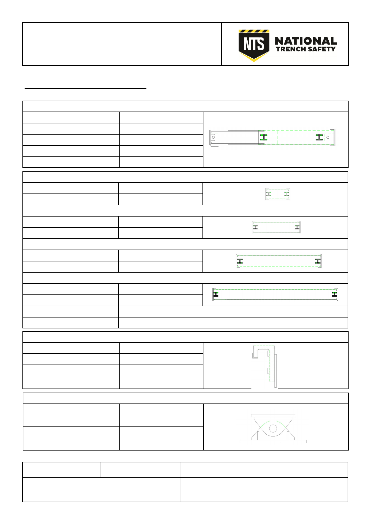
A functional and cost effective hydraulic bracing system:
System 80, heavy duty hydraulic bracing system – suiting larger sized cofferdams
Double acting hydraulic jacks, combine with a range of fixed length extensions & struts, to enable a quick installation
and final removal. Unique, pre-cambered beams, enhancing clear span openings and minimising beam deflection
when loaded.
Assembly
All components should be laid on timber skids, outside of the excavation.
All lifting must be carried out by operatives trained as slinger/ banksman. Familiarisation of the loads is essential be-
fore lifting - ensure that suitable 2 leg or 4 leg chains are selected (recommend 13mm chains).
Due to the weight of the components, it is recommended that the minimum sheet thickness is 8mm and the sheet
piles/ trench sheets are fully toed in.
Excavate to the required depth, as stated on the design, in order to install the first frame (usually a max of 1000mm).
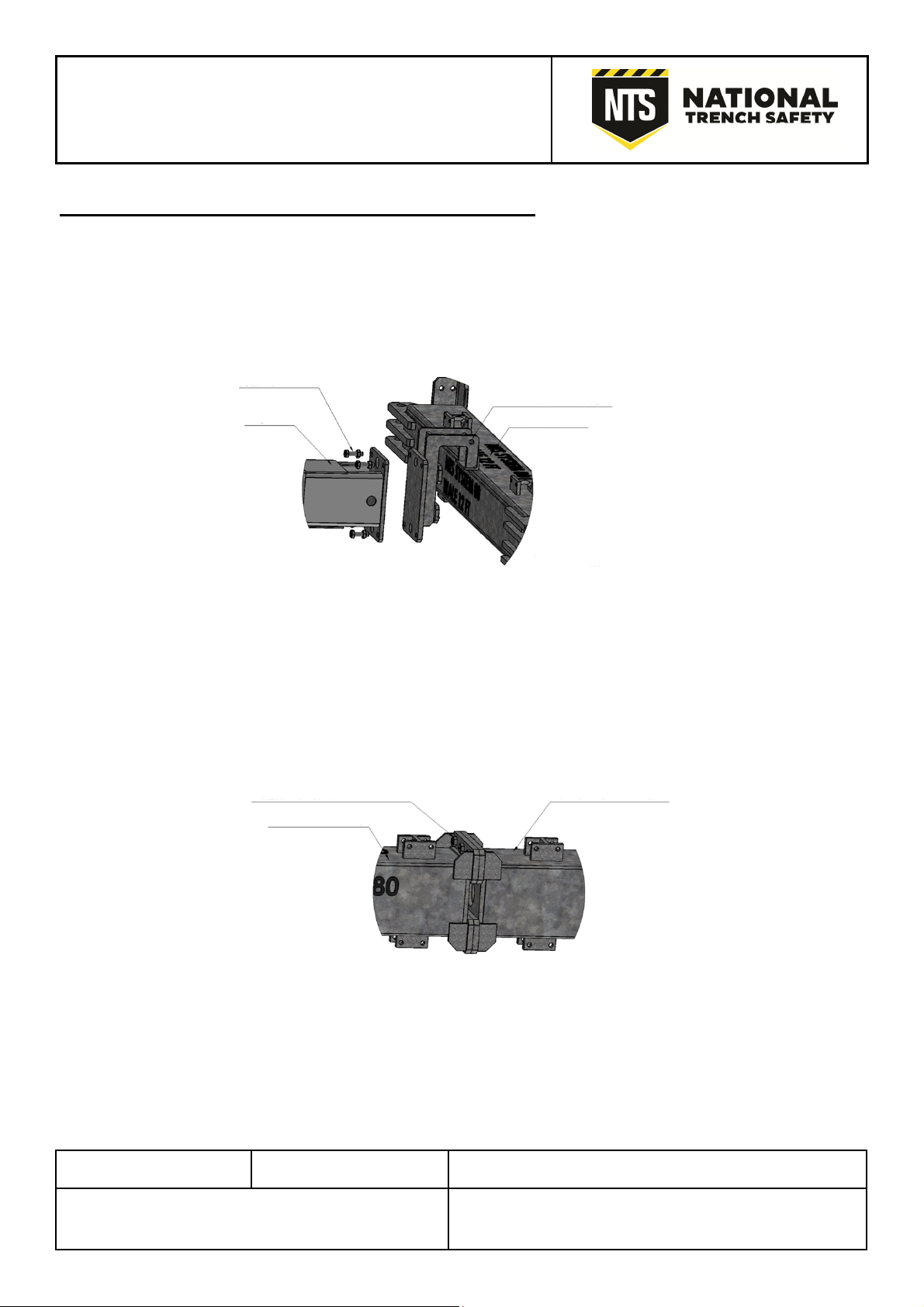
The components can be lowered into the excavation, onto suitable timber skids or pre-installed gallows brackets.
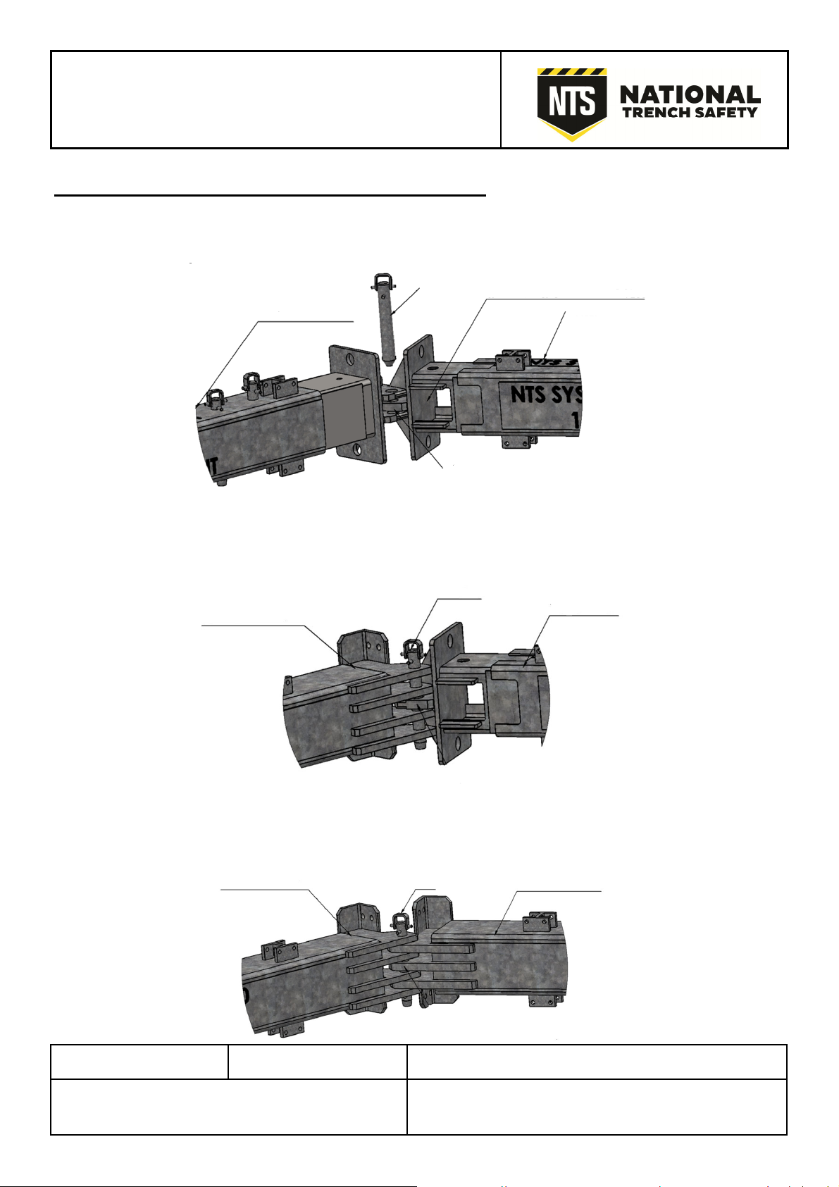
Line up the connecting lugs and insert the pins, to form the continuous legs (ensure that back plates are also fully
bolted at each connection. (Note if the crane/ excavator is capable, fully connected components can be lowered to-
gether).
The hydraulic ram is extended and retracted, using the NTS motorised pump. Connect the hoses, as described in the
NTS Motorised Shoring Pump Guide.
Extend the rams to make connection across the four sides of the excavation. It is recommended that a pre-load of
100 Bar / 1500 psi is not exceeded. Check the frame for alignment and level - note the precam-ber in the waling
beam will straighten when loaded.
Ensure that the design installation sequence is followed.
The system is compatible with knee bracing (using swivel units) and hydraulic struts, which are installed, once the
four sided bracing system in installed and pumped out. Note: Struts have a maximum range of 200t up to 16m.
Removal
Removal is a reverse of the installation, ensuring material is backfilled and compacted as the extraction proceeds.
Maintenance
Prior to making entry to the supported excavation, ensure all components are fitted and show no signs of damage or
fatigue or fluid/ pressure loss. Safe means of access/ egress should be provided, using NTS ladder access / ladders
and Davit Systems.