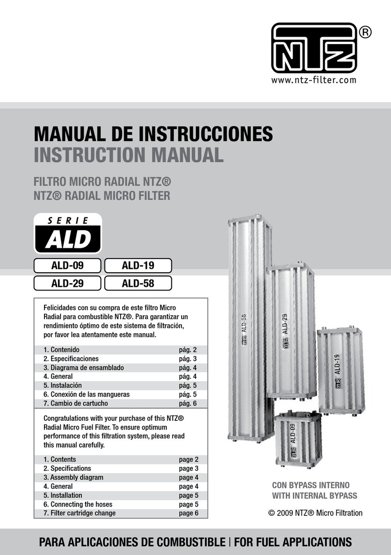
NTZ ALH series User manual

MOBIELE HYDRAULIEK | FOR HYDRAULIC APPLICATIONS
INSTALLATIEVOORSCHRIFTEN
INSTRUCTION MANUAL
NTZ® MICRO RADIAL BYPASS OIL FILTER
ALH-09
Gefeliciteerd met uw aanschaf van dit NTZ®
Radiale Bypass Filter. Om optimaal voordeel van
dit filtersysteem te hebben, adviseren wij U de
handleiding zorgvuldig te lezen.
Congratulations with your purchase of this NTZ®
Radial Micro Bypass Filter. To ensure optimum
performance of this filtration system, please read
this manual carefully.
1. Inhoud
2. Specificaties
3. Installatie
4. Hydraulische aansluiting
5. Filter element wisselen
6. Garantie
1. Contents
2. Specifications
3. Installation
4. Hydraulic installation
5. Filter cartridge change
6. Warranty
pag. 2
pag. 3
pag. 4
pag. 6
pag. 6
pag. 7
page 2
page 3
page 4
page 6
page 6
page 7
ALH-19
ALH-58ALH-29

1. INHOUD / CONTENTS
Qty
8
1
2
1
1
1
1
1
1
1
1
2
4
2
4
1
1
A
B
C
D
E
F
G
H
I
J
K
L
M
N
O
P
Q
Pos.
M8 hexagon cap screws
Top lid
O-ring
Pressure spring
Pressure ring
Bypass 5,5 bar
Filter cartridge
Filter housing
Bottom lid
Flow control valve
Manometer
M 10 Bolt
M 10 Nut
M 10 Washer
M 10 Spring washer
Innerlid
Banjo bolt with 7mm restriction
M8 inbusbouten
Bovendeksel
O-ring
Drukveer
Drukdeksel
Bypass 5,5 bar
Filterelement
Filterhuis
Onderdeksel
Flow control valve
Manometer
M 10 bout
M 10 moer
M10 onderlegring
M 10 veerring
Drukdeksel
Banjobout met 7mm doorlaat
EN
B
C
Q
C
I
G
LMNO
A
F
H
E
K
P
J
D
NL

3
F-09
cellulose
Ø78 x 90 mm
160 g
radiaal /radial
221 cm2
0.5 micron
Beta (ß)
4>10649
Buna NBR
1,0 ltr/min
N.A.
F-19
cellulose
Ø78 x 180 mm
300 g
radiaal /radial
442 cm2
0.5 micron
Beta (ß)
4>10649
Buna NBR
1,5 ltr/min
N.A.
F-29
cellulose
Ø78 x 300 mm
460 g
radiaal /radial
735 cm2
0.5 micron
Beta (ß)
4>10649
Buna NBR
2,1 ltr/min
N.A.
F-58
cellulose
Ø78 x 600 mm
920 g
radiaal /radial
1470 cm2
0.5 micron
Beta (ß)
4>10649
Buna NBR
4,2 ltr/min
N.A.
Filterpatroon
Filter cartridge
Filtermedium
Filter media
Afmetingen
Dimensions
Gewicht
Weight
Doorstroming
Flow direction
Filteroppervlak
Filter surface
Filter fijnheid
Retention value (nom.)
Nominale flow
Nominal flow
Monitor connections
Connections monitor
Afdichtingen
Seals
Filter efficientie
Filter efficiency
ALH-09
180x120x150
1,8 kg
225 liter
M12 X 1,5
10 / 420 Bar
5,5 Bar
100°C
180 cSt
manometer
JIC UNF
9/16-18
10 / 12 mm
ALH-19
260x120x150
2,6 kg
450 liter
M12 X 1,5
10 / 420 Bar
5,5 Bar
100°C
180 cSt
manometer
JIC UNF
9/16-18
10 / 12 mm
ALH-29
380x120x150
3,7 kg
750 liter
M12 X 1,5
10 / 420 Bar
5,5 Bar
100°C
180 cSt
manometer
JIC UNF
9/16-18
10 / 12 mm
ALH-58
680x120x150
6,3 kg
1500 liter
M12 X 1,5
10 / 420 Bar
5,5 Bar
100°C
180 cSt
manometer
JIC UNF
9/16-18
10 / 12 mm
Materiaal behuizing
Material housing
Afmetingen (hxbxd)
Dimensions (mm)
Gewicht
Weight
Tankinhoud (richtlijn)
Sump volume in liters
Aansluiting retour
Connection OUT
Min./Max werkdruk str. regelventiel
Operating Pressure Min./Max.
Bypass setting
Bypass setting
Max. temperatuur
Max. temp.
Max. viscositeit
Maximum viscosity
Indicator
Indicator
Aansluiting perszijde
Connection Pressure
Diameter persslang / retourslang
I.D. Pressure hose / diameter return hose
Filter type
Filter type
Aluminium
Geanodiseerd
Aluminium
Geanodiseerd
Aluminium
anodized
Aluminium
anodized
2. SpECIFICATIES / SpECIFICATIONS

3. INSTALLATIE / INSTALLATION

5
--Monteer de bijgeleverde manometer. Verwijder hiervoor eerst het bovendeksel en het element.
--Verwijder de stofdop in het filterhuis.
--Gebruik voor de installatie van de manometer een draadafdichting met een temperatuur besten-
digheid tot ca. 150 graden Celsius (bv Loctite 542 of vergelijkbaar). Voorzie de draad van de mano-
meter van de draadafdichting en schroef de manometer in het profiel. De manometer is voorzien
van conische draad. Zorg ervoor dat de schroefdraad van de manometer niet uitsteekt aan de
binnenzijde van het filterhuis; anders kan het element beschadigen.
--De filterunit wordt aangeleverd met 1 “IN” (druk) en 1 “OUT” (retour) aansluiting. Monteer het
filtersysteem met de aansluitingen aan de onderzijde voor een eenvoudige uitwisseling van het
filterpatroon.
--Maak gebruik van de bijgeleverde 10 x 50 bouten om het NTZ Bypass filter op de gewenste positie
te monteren. Let hierbij op het volgende:
--Monteer het filterhuis op een plaats vrij van trillingen. Houdt de slangen zo kort mogelijk. Niet
scherp buigen, niet strak spannen. Let erop dat er boven het filterhuis genoeg ruimte is om het
patroon te wisselen (zie tabel…).
--Houdt er bij installatie rekening mee, dat de manometer (optie) goed af te lezen is.
--To enable installation of the pressure gauge, first the upper lid and the filter element must be
removed.
--Remove the plastic plug from the filter housing.
--Apply thread sealing paste with a temperature resistance up to 150 degrees Celcius (eg. Loctite
542 or equivalent) on the thread of the pressure gauge and screw it into the filter housing. The
gauge is equipped with conical thread. Make sure the thread of the gauge does not stick out on the
inside of the filter housing, otherwise the element will damage.
--The filter system has been equipped with a “IN” (pressure) and a “OUT” (return) connection. Mount
the filter system with connections facing downwards, to enable an easy exchange of the filter
cartridge.
--Mount the filter system at the desired location using the supplied M10 x 50 hexagon bolts, taking
the following in consideration:
--Mount the filter system on a spot free from vibrations. Keep hoses as short as possible. Do not
bend or tense hoses. Assure there is enough space to be able to change the filter cartridge.
--Assure that the pressure gauge is properly legible.
3. INSTALLATIE / INSTALLATION

--De toevoerdruk op de “IN” aansluiting (JIC UNF 9/16-8) dient minimaal 10 bar en mag maximaal
420 Bar zijn. Selecteer een aanvoerpunt met een constante druk, bij voorkeur de vulpomp van het
systeem.
--De “OUT” aansluiting (M12 x 1,5) dient drukloos met de tank verbonden te worden. Maak daarbij
geen gebruik van bestaande retourleidingen. Een overdruk van maximaal 1 Bar in de tank is geen
bezwaar. MONTEER GEEN RESTRICTIES IN DE TANKLEIDING!
--Gebruik voor de persleiding hydrauliekslang (diameter 3/8” BSP) welke geschikt is voor een werk-
druk van minimaal 500 bar voorzien van bijbehorende slangkoppelingen. Geen lage drukslang
toe te passen.
--Gebruik voor de retour een 2 staalinlage hydrauliekslang (diameter 1/2” BSP) voorzien van bijbe-
horende slangkoppelingen om zo min mogelijk retourdruk te creëren. Wij adviseren geen lage
drukslang toe te passen. Houd de retourleiding zo kort mogelijk!
--Gebruik bij de installatie de juiste hydrauliek koppelingen. Gebruik onder geen enkele voor-
waarde Loctite of tape.
4. HyDRAULISCHE AANSLUITINg / HyDRAULIC INSTALLATION
--The pressure on the “IN” connection (JIC UNF 9/16-8) should have a minimum of 10 bar and a
maximum of 420 bar. Select a feed point with a constant pressure, preferably the filling pipe of the
system.
--The return hose on the “OUT” connection (M12 x 1,5) must be connected to the tank without pres-
sure. Do not use existing return lines. A maximum pressure of 1 Bar in the tank is allowed. DO NOT
MOUNT ANY RESTRICTIONS IN THE RETURN LINE!
--Use appropriate high pressure hydraulic hoses (diameter 3/8” BSP) equipped with proper connec-
tions to establish the pressure line. Do not use hoses for low-pressure applications.
--To establish the return line use double steel-layered hydraulic hoses equiped with the appropriate
connectors . To ensure minimal return pressure use a return hose with 1/2 “BSP diameter. Do not
use hoses for low-pressure applications. Keep the return line as short as possible!
--Use proper hydraulic connector materials. Do not use tape or sealing liquid!
5. FILTER ELEMENT wISSELEN / FILTER CARTRIDgE CHANgE
--Wissel elementen bij een druk over het filter van 5,5 Bar (bij werktemperatuur!) of tenminste elke
6 maanden.
--Controleer of er een overdruk op de tank staat. Laat de druk zonodig aflopen.
--Zorg er altijd voor dat bij het wisselen van elementen de filter unit drukloos is.
--Haal het vervangingspatroon en de O-ring uit de plastic zak.
--Schroef het bovendeksel van het filterhuis en verwijder de drukdeksel met de veer.

7
5. FILTER ELEMENT wISSELEN / FILTER CARTRIDgE CHANgE
--Verwijder het gebruikte patroon en stop deze in de plastic zak. De nieuwe patroon in het huis
plaatsen en stevig op de bodemplaat drukken. Plaats de drukplaat met veer terug op het nieuwe
filterpatroon.
--Verwissel de O-ring, reinig de afdichtvlakken en schroef het bovendeksel weer stevig vast. Zet de
inbusbouten vast met een aanhaalmoment van minimaal 9 Nm en maximaal 12 Nm.
--Start het systeem totdat deze op bedrijfstemperatuur is en controleer op lekkage.
--Controleer ook het oliepeil. Olie naar behoefte bijvullen.
--Controleer of de olie goed door de bypass stroomt. Als het huis en de slangen warm worden,
functioneert het systeem goed.
--Filter cartridge needs to be replaced when the pressure over the filter at operating temperature is
5,5 Bar or every 6 months.
--Check for pressure on the tank. Relief the pressure of the system when necessary.
--Ensure that the filter system is pressure-less when replacing the filter cartridge.
--Remove the filter cartridge and spare O-ring from the packaging.
--Remove the lid from the system and take out the pressure plate with spring.
--Remove the used filter cartridge and place it in the plastic bag for proper disposal. Place the
new filter cartridge in the filter system and place the pressure plate with spring back on the filter
cartridge. Replace the O-ring, clean the sealing surfaces and put the lid back on the filter system.
Tighten the inner hexagon bolts with a torque of minimal 9 Nm and maximal 12 Nm.
--Start the system until it has reached its operating temperature and check for leakages.
--Check the oil level in the system and top up the necessary quantity.
--Check if the oil runs through the bypass properly. If the hoses and the filter housing warm up, the
filter system operates properly.
1. FILTER SYSTEEM
Op de NTZ® filterhuizen (niet de bijbehorende O-ringen en appendages) geven wij een materiaal-
garantie van 3 jaar na factuurdatum. Indien gebreken worden geconstateerd, dient de koper onverwijld
zijn NTZ®-dealer op de hoogte te stellen. Als de gebreken gegrond zijn, zal het NTZ® filtersysteem
kostenloos worden gerepareerd danwel vervangen.
2. LANGERE OLIE STANDTIJD
Wanneer juist geïnstalleerd, garandeerd NTZ® een probleemloze werking van het filter systeem en de
positieve effecten voor het systeem waar het filter op geïnstalleerd is. Door juiste toepassing van het
NTZ® systeem kunnen langere olie standtijden worden bereikt. De conditie van de olie en de standtijd
van de olie is evenwel mede afhankelijk van het advies van de fabrikant, bedrijfsomstandigheden, type
olie en het systeem waarop het filter wordt gemonteerd. Als gevolg van deze voorwaarden die buiten
6. gARANTIE / wARRANTy

6. gARANTIE / wARRANTy
de invloed van NTZ® vallen, is het verlengen van de oliestandtijd de volledige verantwoording van de
gebruiker. De gebruiker dient zich door middel van olie-analyses regelmatig ervan te verzekeren dat de
olie nog in goede conditie is. Op aanvraag kan NTZ® hierbij assisteren.
3. GARANTIE VAN UW INSTALLATIE / MACHINE
In het geval van materiële schade aan de installatie/machine, vergoed NTZ® de kosten voor reparatie
met inachtneming van de volgende condities: De documentatie van de schade is de verantwoordelijk-
heid van de gebruiker.
•- De installatie/machine valt binnen de garantieperiode van de fabrikant
•- De gebruiker moet aantonen dat de schade is ontstaan door toedoen van een NTZ® filter sys-
teem, welke op juiste wijze is geïnstalleerd en toegepast.
•- De gebruiker moet met historische data van olie-analyses kunnen aantonen dat de olie in de
installatie/machine ten tijde van de opgetreden schade binnen de vereiste specificaties viel.
4. AANSPRAKELIJKHEID
De bovengenoemde garantie en de aansprakelijk van NTZ® zullen nimmer verder strekken dan voor
(gevolgen van) gebreken aan het NTZ® filter. Schaden die anderszins of door derden ontstaan, zoals
door montagefouten bij de installatie, door onjuiste aansluiting op het oliecircuit of door aansluitdelen
of slangen, vallen niet onder deze garantie, noch onder onze productaansprakelijkheid. Voor het door
NTZ® geleverde montagemateriaal geld de garantie van de leveranciers/producenten van deze materia-
len, welke wij aan onze klanten doorgeven.
5. GARANTIE VERVALT INDIEN
•- Het NTZ®-filter is onzorgvuldig of in strijd met de aanwijzingen en/of de gebruiksaanwijzingen zijn
behandeld, danwel zijn aangewend voor niet geëigende doeleinden;
•- geen originele NTZ® filterpatronen zijn toegepast
•- geen geldige gedateerde aankoopfactuur kan worden overlegd
•- het defect en/of de schade is ontstaan door een natuurlijke ramp, ongeval, misbruik, verkeerd
gebruik of enige andere van buiten komende oorzaak.

9
6. gARANTIE / wARRANTy
1. FILTER SYSTEM
NTZ® grants a 3-year limited warranty on the NTZ® filter housing (excluding the accompanying
o-rings) from the date of invoice. In the unlikely event that the purchaser finds a defect, the purchaser
must notify their NTZ® dealer. If the defect is justified, the NTZ® filter housing will be replaced or
repaired free of charge. Any claims to NTZ® filter housings should be addressed directly to your NTZ®
point of contact. A claim should contain a clear description of the findings, including pictures and specifi-
cations of the application, along with a copy of the invoice.
2. EXTENDED OIL LIFE / DRAIN INTERVALS
When properly installed, NTZ® guarantees the effective filtering operation of the NTZ® filter and its
positive effects for the equipment. Extended oil drain intervals are achievable with the proper use of the
NTZ® system. However, the condition of the oil and the oil change intervals are also dependent upon
the original equipment manufacturer, operating conditions, selection of lube/oil, and system type. Due
to conditions out of the control of NTZ®, the length of any extended drain interval is at the discretion of
the customer. The customer should perform regular oil analysis to ensure that the condition of the oil is
within the recommended specifications as set by the original equipment/oil manufacturer. Upon request,
NTZ® can aid in this activity.
3. EQUIPMENT WARRANTY
In the unlikely event of material damage to the equipment, NTZ® warrants the entire cost of repair
under the following conditions (Documentation of which is the full responsibility of the claimant):
• The equipment is well maintained and worked properly at the moment of installation which can be
proven by copies of the maintenance and repair history of the equipment.
• The NTZ filter is installed by a certified mechanic.
• The user must demonstrate the device damage is due to the malfunction of a properly installed
and properly used NTZ® filter system.
• The customer must demonstrate from actual data or from a documented extended drain interval
program (historical data) that the oil or lube fluid in the device was within the proper usage specifi-
cations at time of failure.
4. LIABILITY
The above mentioned warranty and NTZ’s liability does not extend beyond (the consequences of) defects
in the NTZ® filter. Damage as a result of other means or caused by third parties, such as by errors
during installation, by incorrect mounting onto the oil circuit or by mounting devices or hoses are not
covered, neither by this warranty nor by NTZ’s product liability. With regard to mounting pieces supplied
by NTZ® the warranty applicable is the warranty of the suppliers/producers of the mounting pieces
which is passed on by NTZ® to its customers. Liabilities are limited to the amounts mentioned in the
insurance policy for liability risks that NTZ has concluded with N.V. Interpolis. No claim shall exceed Euro
2.500.000. The maximum annual amount of damages covered shall not exceed Euro 5.000.000.
5. BREACH OF WARRANTY POLICY
The warranty is non-applicable (breached) by user if and when:

6. gARANTIE / wARRANTy
• The NTZ® filter is handled without due care or in contradiction with the instructions for use, or if
used for purposes other than its suggested purpose.
• Cartridges other than original NTZ® filter cartridges have been applied.
• The NTZ® filter is reinstalled onto an installation (engine, transmission, hydraulic application) other
than indicated on the warranty certificate.
• No valid dated purchase invoice/warranty certificate can be produced.
•- The defect and/or the damage is a result of a natural disaster, accident, misuse, incorrect use or
any other outside cause for which NTZ® is not liable.
In case of disputes Dutch law is applicable.
This manual suits for next models
4
Table of contents
Other NTZ Water Filtration System manuals
Popular Water Filtration System manuals by other brands

BWT
BWT AQA nano Fitting and operating instructions

WilTec
WilTec ECF-15000 instruction manual

Vortex
Vortex 85-1448-10 (10 GPM) Installation and service manual

Propur
Propur ProMax instruction manual

Mi-T-M
Mi-T-M FRO-1000-0ME1 Operator's manual

Greiner Vibrograf
Greiner Vibrograf ACS 900 Manual and instruction