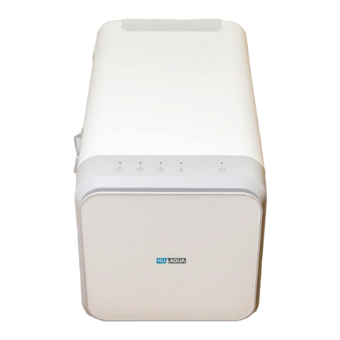
NU Aqua Efficiency Series User manual

800GDP Tankless RO
Installation Manual
For NU Aqua Product ID (SKU):
WU-800GPD-TL
WU-600GPD-TL
(600GPD Versions)

Congratulations
on Your New
Reverse Osmosis
System
Scan here
for link to video Watch the complete
installation guide at
nuaquasystems.com/install

Table of contents
Introduction
Conditions Page 4
Introduction Page 5
System Requirements Page 5
Preparation
Inspection Page 6
Recommended tools Page 6
Installation components Page 6
Quick connect guide Page 7
Tube cutting guide Page 7
Installation
Feed water adapter Page 8
Leak stop valve Page 9
Drain saddle Page 10
Faucet installation Page 11
System installation Page 12
Alkaline system installation Page 13
UV system installation Page 14-15
Alkaline & UV system installation Page 16-17
System use and care
System startup Page 18
Filter changes Page 19
Trouble shooting Page 20
Warranty Page 21-22

4
READ THIS FIRST
• Please pay attention to the following installation and safety recommendations
• Read the installation manual before installing this system.
INCOMING WATER
Incoming water pressure must be between 14.5 PSI and 58 PSI. If your water pressure is above 58 PSI you will
need a pressure regulator for your system. Test your water pressure occasionally to make sure the system is
performing. If your water is microbiologically unsafe or of unknown quality you must use the optional UV Filter
Kit (SKU: HC-UVC1140GPD). Extremely hot or cold incoming water will damage the system and cannot be used.
Do not install where water hammer conditions exist, you should install a water hammer arrestor.
LEAKS
The included leak stop valve must be installed. Inspect all connections after the installation to make sure no leaks
occur, wait until after the system is pressurized (turned on) to inspect again. Check the system occasionally
after installation or maintenance to make sure no leaks have developed. Install the system in a location with
adequate drainage.
GENERAL
This RO system unit is for climate controlled indoor use only. Exposure to overly high or low temperature ranges
will damage the unit. Follow all of your state and local laws and codes regarding plumbing even if they dier
from what is stated in this manual. If your state law requires it or you prefer to, we recommend using a professio-
nal licensed installer or plumber who meets the requirements of this system. All O-Rings, fittings, tubing, filter
canisters, and teflon tape wear out after a certain period of time. The lifetime of your components are subject
to change with the quality of the water supplied. Use appropriate eye and face protection when performing
any drilling.
MAINTENANCE
The owner/user is obligated to properly maintain the RO system when necessary. This includes the following:
• Always use NU Aqua Systems replacement filters in accordance to the filter change schedule.
At least every 3 years:
• Replace the tubing, and fittings.
• Replace the teflon tape on all threaded connections and fittings.
At least every 5 years:
• Replace the faucet.
LIMIT OF LIABILITY
In all circumstances, NU Aqua System’s maximum liability is limited to the purchase price of the product(s) sold.
NU Aqua Systems is not responsible or financially liable for any water damage, property damage, or personal
injury, direct or indirect, that may occur from normal or correct use of the products we sell, catastrophic failure
of the products we sell, failure to properly connect the units to water supply lines, and/or failure to understand
and observe the proper water pressure ratings and requirements for these units. Use, install and monitor all of
our products solely at your own risk. Always check all connections for leaks periodically. NU Aqua Systems is not
responsible for any leaks or water damage. In case some states do not allow the exclusion or limitation of
incidental or consequential damages, you may choose to return the system. If you choose to keep it, you insist
this exclusion still applies to you.
Conditions READ THIS FIRST
-Please pay attention to the following installation and safety recommendations:
-Read the installation manual before installing this system.

5
Thank you for your purchase of the NU Aqua reverse osmosis drinking water system. We're excited for you to
experience the benefits of a premium home water filter system and hope that you are as well. This guide is
intended to make your installation pain free and can be followed step by step with our installation video.
Introduction
WANT YOUR FILTERS DELIVERED AUTOMATICALLY?
JOIN THE FILTER CLUB AND GET YOUR FILTERS AT A DISCOUNT.
Scan Me!
Stage Description Service life
System Requirements
System Operating Pressure: 14.5 - 58 PSI
Incoming Water Temperature: 40° - 100°F (5°-38°C)
Water Pressure Must Not Exceed 58PSI
Temperature must not exceed 100°F or go below 40°F
System is for indoor use only
Optional: Ultraviolet filter
SKU: HC-UVC1140GPD
Optional: Alkaline filter
SKU: WU-STG1-ALK-CT
8 - 12 Months
6 - 7 Years
3 - 6 Months
6 - 12 Months
24 - 36 Months
800GPD Reverse osmosis membrane
SKU: WU-S3800MB-TL
2 in 1 Carbon block & polypropylene filter
SKU: WU-S1SCB-TL
Granular activated carbon filter
SKU: WU-S2GAC-TL

6
After unpacking your new RO system and all the components, we recommend that you thoroughly inspect all
fittings and tubing to ensure nothing has come loose during shipping. If any part appears cracked or broken
from shipping, do not proceed with installation and contact us directly.
Email: support@nuaquasystems.com
Phone: 1(888) 621-0460
Inspection
Drill with a 1/4"
and 5/8" drill bit
Open ended
wrench
Phillips
screwdriver
Razor blade 14 mm
wrench
Recommended Tools
Installation Components
Optional Components
Drain saddle
Quick connectorFaucetPower Supply
Feed Water
Adapter
Filter Set
3/8” Tubing
1/4” Retaining Clip
Alkaline Filter Kit
UV Filter Kit
1/4” TubingLeak stop valve
RO System
3/8” Retaining Clip

7
Tubing/Fittings/
Plug Removal
If there is a retaining clip on the collet of the fitting
it must be removed first. Push and hold the collet
down to unlock the tubing and gently pull the
tube/fitting/plug to remove it.
Quick Connect Guide
Install or Remove
Retaining Clips
To lock a tube in it’s fitting make sure that it is fully
inserted. Slide the retaining clip between the collet
and fitting. Before tubing can be removed from a
fitting you must remove this clip first. To remove the
retaining clip simply pull the clip away from the
fitting until it slide completely out.
Insert Tubing
Push the tubing straight and level into the fitting.
When inserting the tubing make sure you push until
it stops to ensure the lock is activated. The tubing
will travel 5/8” into the fitting. Gently pull on the
tubing to check that the lock is activated.
How to Cut Tubing
When cutting the supplied tubing its important to
use a sharp razor blade. Place the tubing on a flat
surface and cut straight through the tubing. All cuts
to your tubing must be perfectly straight to ensure
the best connections.
NOTE:
Always check each connection
to make sure its secure
NOTE:
Improperly cut tubing may cause
a leak
Plug
Collet
Locking
Clip
Pull Up
Hold
Down
Unlocked Locked
5/8” 5/8”
OK
X

8
Installation
Feed Water Adapter
1. Locate and turn o the cold water
valve under your sink. Next turn on the
cold water faucet to drain any remai-
ning water in the line
2. Place a towel below your cold water
valve to catch any remaining water in
the line. Loosen the nut on the water
line where it is attached to the valve.
The feed water adapter can be instal-
led in either location A or B as illustra-
ted in the diagram.
3. Wrap the threads of the water valve
and feed water adapter 8-10 times with
teflon tap. using a adjustable wrench
secure the feed water adapter onto the
cold water valve and the water line to
the feed water adapter.
4. Turn the feed water valve to the o
position for the remainder of the instal-
lation process.
5. Insert one end of your 3/8” tubing
into the quick connect fitting on your
feed water adapter. Secure in place
with a retaining clip.
WARNINGS:
Only connect to cold water line.
Hot water will damage your system.
WARNINGS:
Turn the hot water valve o when
installing on a single handed faucet.
1/2” Connection 3/8” Connection Open Closed
Adapter
Adapter

9
Installation
Leak Stop Valve Installation
1. Locate the lowest point within your cabinet or installation
location. Using the included screws, secure your leak stop
valve in this location
2. Locate the 3/8” tubing coming from the feed water
adapter and cut it near the location of the leak stopper.
Connect the end of the tubing coming from the feed water
adapter to the quick connect on the leak stop valve labeled
“in”.
3. Take o the plastic wrap o the leak cartridge and place
it inside the leak stop valve as shown.
4. Turn the leak stop valve switch down to put it in the on
position.
WARNING:
Failure to install Leak Stop Valve will
void Warranty
NOTE:
It may be best to insert the cartridge after
the initial startup is complete
3/8” Tubing
Flow Closed
Position
Flow Open
Position
3/8” Tubing

10
Installation
Drain Saddle
1. Locate a section on your drain plumbing using the
image above and mark the location with a pen. If the
drain saddle is to be installed on a horizontal section
you must position the hole on top of the pipe.
2. Use a drill with a 1/4” drill bit on the section you
marked. Be careful to drill only through one side of
the pipe.
3. Remove the center of the foam pad included with
the drain saddle. Peel o the adhesive tape on the
back side and attach it to the drain saddle half with
the quick connect fitting. Make sure the center hole
aligns with the hole in the drain saddle.
4. Press the two nuts into the back of the drain
saddle by hand.
5. Slide a small screwdriver through the quick
connect fitting on the drain saddle half and through
the hole drilled in your drain pipe. This will keep the
holes aligned during the installation.
6. While holding the drain saddle in place secure the
back half using the two supplied screws and a screw-
driver. Tighten both screws till the drain saddle is
secure. You may remove the screwdriver holding the
drain saddle in place.
7. Locate your black tubing and insert one end into
the quick connect fitting on your drain saddle.
OK
OK
X
X
OK
Mount Drain
Saddle at either
location
WARNING!
Never mount
there!
X

11
Installation
Faucet Installation
Drilling
If your sink has an existing hole this can be used for your faucet. If you have to drill a new hole follow the
steps below.
1. Locate the section on your countertop to install
your faucet. Using plumbers clay form a ring around
the section you will be drilling. This will be used to
retain water for the drilling process.
2. Fill the ring with water. Using a 5/8” diamond tip
hole saw drill bit slowly begin drilling. Apply light, and
even pressure and let the drill do the work.
1. Locate the section on your countertop to install
your faucet and drill a 1/4” pilot hole. Once comple-
tely drilled through, switch to a 5/8” drill bit and
re-drill the same hole.
Granite / Marble / Quartz sinks
Stainless Sink
Keep the drill bit and hole wet during the drilling process
1. Insert the faucet into the hole in your counter-
top.
2. Slide the rubber washer followed by the metal
washer up the threaded shafter of the faucet and
secure in place with the included nut.
3. Install the quick connect fitting to the threaded
shaft and secure in place with a retaining clip.
4. Connect the 1/4” tubing into the quick connect
fitting and secure in place with a retaining clip
Installation
OpenClosed
Open and Closed Position
Rubber Washer Metal Washer
Nut
Quick Connect Fitting
Retaining Clips
Power Cord
1/4” Tubing

12
System Installation
System Connections
Filter Installation
WARNING: Double check that filters are properly inserted.
Check that the lock icon is aligned on the system and
filter.
For alkaline system proceeed to page 13
NOTICE: If your system comes with the alkaline or UV filter you may
skip this page
For UV system proceeed to page 14
For alkaline and UV system proceeed to page 16
1. Place your reverse osmosis system
under your sink in a location thats easily
accessible.
2. Insert each filter into its corresponding
placement in the reverse osmosis system
and rotate clockwise to lock in position.
Gently pull on the filter to ensure the filter
is locked in place.
1. Connect the 3/8” tubing coming from the leak detector into the IN connection on the back of the reverse
osmosis system. Secure the tubing in place with a retaining clip.
2. Connect the 1/4” tubing coming from the drain saddle into the DRAIN connection on the back of the rever-
se osmosis system. Secure the tubing in place with a retaining clip.
3. Connect the 1/4” tubing coming from the faucet into the OUT connection on the back of the reverse osmo-
sis system. Secure the tubing in place with a retaining clip.
4. Plug the faucet power cord into the FAUCET connection on the back of the reverse osmosis system.
Notice: Do not plug reverse
osmosis system into wall
outlet yet

13
OK
X
Alkaline System Installation
Mounting
1. Secure the filter bracket to the wall of your kitchen cabinet using the
two provided screws.
2. Before connecting the filter check that the o-ring is properly seated
in place.
3. Insert the filter into the bracket and twist clockwise to secure it in
place.
Alkaline System Connections
Notice: Do not plug reverse osmosis system into wall outlet yet
OUTLETINLET
WALL
SCREW
1. Connect the 3/8” tubing coming from the leak detector into the INPUT
connection on the back of the reverse osmosis system. Secure the tubing in
place with a retaining clip.
2. Connect the 1/4” tubing coming from the drain saddle into the DRAIN
connection on the back of the reverse osmosis system. Secure the tubing in
place with a retaining clip.
3. Connect the blue 1/4” tubing to the PURE water connection on the back
of the reverse osmosis system. Connect the other end of the blue 1/4“ tubing
to the INLET of the alkaline filter. Secure both connections with a retaining
clip.
4. Connect the blue 1/4” tubing coming from your faucet to the OUTLET of
the alkaline filter. Secure both connections with a retaining clip.
5. Lastly connect the cord coming from your faucet to the connection on
the back of the system labeled FAUCET.

14
NOTE:
Always check each connection
to make sure its secure
NOTE:
Improperly cut tubing may cause
a leak
UV System Installation
Mounting
There are two mounting options for your UV filter. Option one is a adhesive pad. This is the easiest option
but will be less secure. Option two is a hard mount that is more secure and uses screws to attach to the
inside of your cabinet.
Adhesive
1. Select the location you want to install your UV
Filter. This should be atleast 8 inches above the
bottom of the cabinet.
2. Peel o the backing of the adhesive pad.
3. Firmly press the adhesive pad against the
cabinet wall.
4. Peel o the front cover of the adhesive pad.
Press the mounting plate firmly against the
pad to secure it.
5. Hang the UV water filter on the mounting plate
studs.
Hard Mount
1. Select the location you want to install your UV
Filter. This should be atleast 8 inches above the
bottom of the cabinet.
2. Secure the mounting plate directly to the
cabinet wall using the supplied screws
3. Hang the UV water filter on the mounting plate
studs.
Wall
Hard Mount
Screw
Mounting Plate
Stud
Wall
Hanging
Mounting Plate
Adhesive Mount
Adhesive pad
Mounting Plate
Stud

Notice: Do not plug reverse osmosis system into wall outlet yet
IN
OUT
POWER CORD
NOTE:
Improperly cut tubing may cause
a leak
NOTE:
Always check each connection
to make sure its secure
UV System Connections
15
1. Connect the 3/8” tubing coming from the leak detector into the INPUT connection on the back of the
reverse osmosis system. Secure the tubing in place with a retaining clip.
2. Connect the 1/4” tubing coming from the drain saddle into the DRAIN connection on the back of the rever-
se osmosis system. Secure the tubing in place with a retaining clip.
3. Connect the 1/4” tubing to the PURE water connection on the back of the reverse osmosis system. Connect
the other end of the 1/4” tubing to the IN connection of the UV Filter. Secure the tubing in place with a
retaining clip
4. Connect the 1/4” tubing to the OUT connection on the UV filter. Connect the other end of the 1/4” tubing
to the reverse osmosis faucet. Secure the tubing in place with a retaining clip.
5. Connect the power cord to your UV filter and plug into wall outlet.
6. Plug the faucet power cord into the FAUCET connection on the back of
the reverse osmosis system.

16
OK
UV & Alkaline System Installation
Alkaline Filter Mounting
1. Secure the filter bracket to the wall of your
kitchen cabinet using the two provided screws.
2. Before connecting the filter check that the
o-ring is properly seated in place.
3. Insert the filter into the bracket and twist
clockwise to secure it in place.
UV Filter Mounting
There are two mounting options for your UV filter. Option one is a adhesive pad. This is the easiest option
but will be less secure. Option two is a hard mount that is more secure and uses screws to attach to the
inside of your cabinet.
Adhesive
1. Select the location you want to install your UV
Filter. This should be atleast 8 inches above the
bottom of the cabinet.
2. Peel o the backing of the adhesive pad.
3. Firmly press the adhesive pad against the
cabinet wall.
4. Peel o the front cover of the adhesive pad.
Press the mounting plate firmly against the
pad to secure it.
5. Hang the UV water filter on the mounting plate
studs.
Hard Mount
1. Select the location you want to install your UV
Filter. This should be atleast 8 inches above the
bottom of the cabinet.
2. Secure the mounting plate directly to the
cabinet wall using the supplied screws
3. Hang the UV water filter on the mounting plate
studs.
Wall
Screw
Wall
Hard Mount
Screw
Mounting Plate
Stud
Wall
Hanging
Mounting Plate
Adhesive Mount
Adhesive pad
Mounting Plate
Stud

17
Alkaline & UV System Connections
Notice: Do not plug reverse osmosis
system into wall outlet yet IN
OUT
POWER CORD
OUTLETINLET
1. Connect the 3/8” tubing coming from the leak detector into the INPUT connection on the back of the
reverse osmosis system. Secure the tubing in place with a retaining clip.
2. Connect 1/4” tubing coming from the drain saddle into the DRAIN connection on the back of the reverse
osmosis system. Secure the tubing in place with a retaining clip.
3. Connect the blue 1/4” tubing to the PURE water connection on the back of the reverse osmosis system.
Connect the other end of the blue 1/4“ tubing to the INLET of the alkaline filter. Secure both connections
with a retaining clip.
4. Connect the blue 1/4” tubing to the OUTLET of the alkaline filter. Connect the other end of the 1/4”
tubing to the IN connection of the UV filter. Secure both connections with a retaining clip.
5. Connect the 1/4" tubing to the OUT connection on the UV filter. Connect the outher end of the 1/4"
tubing to the reverse osmosis faucet. Secure the tubing in place with a retaining clip.
6. Connect the power cord to your UV filter and plug into wall outlet.
7. Plug the faucet power cord into the FAUCET connection on the back of the reverse osmosis system.

18
OK
O - Filter Good
O - No Error
O - No Power
Solid White - On
Solid White - 2 Hour Continuous Protection Unplug power supply and reconnect to reset error indicator
Unplug power supply. Check feed water adapter is fully open and
water flows regularly from your kitchen faucet. Reconnect power
supply to reset error indicator.
Flashing White - Standy Mode
Flashing White - Water Shortage
Flashing White - Replace Soon
Solid White - Replace Now
Do not start system without checking each connection
is fully inserted into the quick connect fitting
IMPORTANT: Check for leaks daily during the first two weeks after installation.
NOTE: Your water may have a slightly milky or cloudy color during the first week of use.
This is caused by tiny air bubbles in the water and will go away with use.
NOTE: If your system has an alkaline filter your water’s TDS will register higher. For accurate
testing, testing water that has not been processed by the alkaline filter.
System Startup
System Functions
1. Physically check each connection is fully inserted into it’s fitting and has a retaining clip installed.
2. Slowly open the feed water valve. Wait 1 minute and check for leaks at every connection. If there are any
leaks, close the feed water adapter and open the reverse osmosis faucet to relieve pressure from the
system. Remove the leaking connection and reinsert the tubing. If this does not resolve the issue contact
customer service.
3. Connect the power supply to the power inlet on the back of the revese osmosis system then connect the
power supply to the wall outlet.
4. Hold down the power button on the front of the system until the light next to the icon turns solid.
5. Now we will begin to flush the system. Open the faucet and allow the water to run for 30 minutes. This will
flush the new filters of any loose filter media. It’s normal for your water to have a slight gray tint during this
process and will go away.
NOTE: DO NOT DRINK ANY WATER UNTIL COMPLETING THE FLUSHING PROCESS BELOW.
System Lights
Error Indicator Lights
Faucet Lights
Solid Blue - Filter Good
Flashing Blue - Rinsing In Progress
Flashing Orange - Replace Soon
Solid Orange - Replace Now

19
Filter Changes
1. Close your feed water adapter to stop the flow of water to your system.
2. Unplug the system power supply from your wall outlet. If you have a UV filter disconnect the power supply
from your wall outlet.
3. Rotate the filter counterclockwise to unlock the it and then pull the filter out from the system.
4. Insert your new replacement filter into the system and turn it clockwise to lock it into place. Rotate the
filter so that the lock icon on the filter is aligned with the lock icon on the system.
5. With your new filters installed, open the feed water adapter to allow water into the system.
6. Plug your power supply into your wall outlet as well as your UV filter if your system is equipped with one.
7. Now reset the filter reminder on the system. Hold the button for the corresponding filter number on the
system that you’ve replaced for 3 seconds until the light flashes. The icon light will now turn o indicating
the filter has been reset successfully.
8. Now that your filter has been replaced, you must flush your system again. Open the faucet and allow the
water to run for 30 minutes. Once completed, your system is ready for use.
WANT YOUR FILTERS DELIVERED AUTOMATICALLY?
JOIN THE FILTER CLUB AND GET YOUR FILTERS
AT A DISCOUNT.
Scan Me!

20
Troubleshooting
CausesProblem Solution
• Check for clog in drain line and clear.
•Replace inline carbon filter.
•Replace RO membrane.
• Ensure outlet is not on a switch
• Plug power supply in dierent outlet
• Contact customer support
• Reinsert tubing
• Replace the O-ring.
• Realign drain saddle.
• Replace leak stop valve.
• Check water flows from feed water
adapter. If no water comes through,
• Remove object. This can cause vibrating
noise
• The pump produces a low sound when
operating
• Reconnect faucet plug into system
• Unplug system power supply, wait 10
seconds and plug back in
• Contact customer support
• Open the faucet and let the system run
for 10 minutes
• Replace RO membrane
• Test source water TDS. The pure water
should test 5-10% of your water TDS
• Air in the system is normal with initial
installation and startup. This will clear up
within 1 to 2 weeks.
Milky colored water
Air bubbles in water
Water taste or an
oensive smell
System does not turn on
Leaks
No water
Loud or noisy system
Faucet light not turning on
Water TDS is testing high
• Air in the system
• Drain line clogged
• Inline post carbon filter is
depleted
• no power to system
• Power supply failure
• Tubing not fully inserted
• Twisted/damaged O-ring
• Misalignment of hole in drain
saddle
• Check leak stop valve
• Check feed water adapter valve
• Objects on top of system
• normal sound of pump
• No power to faucet
• Damaged faucet
• System has sat for extended
time
• RO membrane has expired
• High TDS source water
This manual suits for next models
2
Table of contents
Other NU Aqua Water Filtration System manuals
Popular Water Filtration System manuals by other brands

Aquaport
Aquaport AQP-FKM1 Installation & operating instructions

PREMIER TECH
PREMIER TECH REWATECH owner's manual

Lectranator Systems
Lectranator Systems ST 48 manual

JNS Aquaria
JNS Aquaria FR-S quick start guide

Schaffner
Schaffner FN5420 User and installation manual

Kohler
Kohler REVE Series installation guide