Page B.3
PG Series General Information
Modulation By Electronic Cam System
There is some inherent hysteresis in all mechanical
systems that traditionally involve cams and linkages
to characterise the air/fuel ratio.
To improve accuracy, P Series burners are now
normally supplied with a system that overcomes
all of these problems by utilising independently
operated servo-motor driven valves for the fuel and
air and the latest microprocessor technology.
This Micro Modulation system (MM) provides a
programmable and flexible means of optimising
combustion quality throughout the load range of
the boiler/burner unit whilst ensuring the
temperature is accurate to within 1°C and pressure
to within 1.5 psi by utilising P.I.D. control.
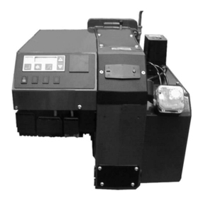
A control module contains a micro computer and
power supply. The display panel features touch-
sensitive key pad data entry, readouts and status
indicators; all protected beneath a tamper-proof
transparent plastic cover.
During commissioning, the paired values for fuel
and air are entered into the memory of the module.
Upto 15 positions in the load index of the burner’s
fuel delivery range are entered from maximum
down to the minimum start position. This
guarantees operation at the air/fuel ratios set during
commissioning.
By removing the inherent hysteresis of traditional
mechanical systems, combustion quality and fuel
efficiency are greatly improved.
The M.M. system may be expanded, by adding a
sampling unit and exhaust gas sampling probe, to
measure and display CO2, O2, CO and exhaust
temperature, together with boiler efficiency. This
is the M.M. Exhaust Gas Analysis Trim System
(M.M.E.G.A.).
This makes very small corrections to the air damper
position to ensure that the originally entered
commissioning data is adhered to, irrespective of
variations in stack pressure or barometric
conditions.
SITE CONDITIONS AND SERVICES
Flue and Chimney Requirements
It is important that:
- the flue pipe from the appliance and the joint
between this flue and the chimney are sealed
to prevent leakage of combustion products
- the flue pipe from the appliance does not
protrude into the chimney beyond the inside
wall
- the top of the flue or chimney shall be higher
than any roof within a radius of 10 metres
- checks are made to ensure that the chimney
is suitable for gas and oil-fired appliances and
that the proposed installation complies with
all ocal Authority and other regulations
covering such installations
- if more than one appliance is connected to a
common flue or chimney, the cross section
of this flue or chimney should be adequate
for the total volume of combustion products
from the appliances
- it is recommended that each appliance
should be exhausted into a separate flue.
Plant Room Ventilation
An adequate dust-free supply of fresh air is required
for the burner at both high and low levels in
accordance with the appropriate standards.
Existing Appliances
The appliance should be prepared for installation
of a P Series burner by thorough cleaning, including
the removal of all adhering tar, scale and dirt. An
inspection should also be carried out to ensure that
the appliance is in good condition. Any doubt
about the suitability of the appliance should be
referred to the manufacturer.
as Supply
The pipework supplying the gas to the burner, must
be appropriate to local conditions and must be
constructed and installed in compliance with
appropriate Codes and Standards. It shall be of
sufficient size to satisfy the pressure and volume
flow requirements of the burner under all firing
conditions. Checks should be made to ensure that
all meters and other components are appropriately
rated for the maximum gas flow rate that is
anticipated. It is essential that a 90° manual isolation
valve is fitted upstream of the gas control train to
allow the burner to be isolated for maintenance.
The size of this valve should not be less than that
of the burner control train in order to avoid any
restriction to gas flow.
Natural gas is the usual fuel and has to be supplied
at an appropriate pressure, these pressures are
presented on the Burner Specification Sheet on
Page C.2 Technical Specifications
