BURNERGASCONTROLS
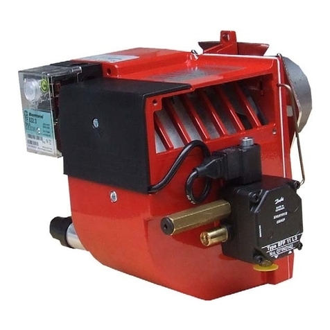
Low Gas Pressure Switch
The low gas pressure switch is
located on the inlet side of the gas
valve. It is required to monitor inlet
gaspressureduringburneroperation.
Thelow gas pressureswitch iswired
in series with the appliance
controlling instruments and in the
event of gas pressure failure will
cause the burner to effect a safety
shut down.
Isolate the burner and remove the
gas pressure switch cover. Switch
ontheelectricalsupplyandallowthe
burnertoestablishmainflame.Slowly
turn the adjustment dial on the gas
pressure switch clockwise until the
flameisextinguishedandtheburner
shuts down. Turn the dial slowly
anticlockwiseone division ata time
until the burner restarts and
establishesmainflame.Recheckthe
performanceandthenturnthediala
further two divisions anticlockwise.
Switchofftheburnerandreplacethe
gas pressure switch cover.
Gas Valve Multibloc - Single
Stage (On/Off)
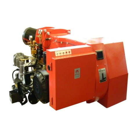
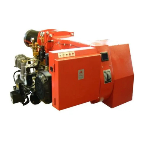
Thegasvalveisofthemultibloctype
incorporating start rate, safety and
main valves and pressure governor.
Valveadjustmentsaredetailedinthe
Gas Controls and Adjustments
section.
SG10060602
Two Stage (High/Low)
Thegasvalveisofthemultibloctype
incorporating startrate,safetyandtwo
stage valve and pressure governor.
Valveadjustmentsaredetailedinthe
GasControlsandAdjustmentsection.
FLAMEMONITOR
Probe
Theflame probe (flame rectification
probe)is locatedon theburner head
and is required to supervise the safe
operation of the burner under all
working conditions.
UV
As an option burners can be fitted
with an ultraviolet cell (UV) cell to
detect the presence of the flame.
BURNEROPERATING
SEQUENCE
Single Stage (On/Off) Burners
Theoperating sequence beginswith
apre-purgeon fullair,then startrate
gasflame which whenproved allows
theburnerto operate onmainflame,
then to the “OFF” position after the
heatinput issatisfied. Theoperation
is determined by demand of the
appliance control instruments.
GENERAL INSTRUCTIONS continued......
Two Stage (High/Low) Burners
Thesequencebeginswithanair pre-
purgeonfullair,followedbystart rate
gasflame which whenproved allows
the burner to operate on High/Low/
Off. The operation is determined by
the demand of the appliance control
instruments.
FLUEANDCHIMNEY
REQUIREMENTS
Thetop of theChimney/Flue should
be above all roofs within a radius of
10 metres.
Check that it is suitable for use with
gas fired appliances. Reference
should be made to Local Authority
andother regulations governingsuch
installations.
Ensure that the flue pipe from the
appliancedoes notprotrude intothe
chimney beyond the wall thickness
and is sealed throughout its run.
If more than one appliance is
connected to a common flue/
chimney, ensure that the cross
section of the flue/chimney is
adequatefor thetotal volumeof flue
gases from all the appliances.
PLANT ROOM VENTILATION
An adequate supply of dust free,
fresh air is required for the burner at
bothhighandlowlevelinaccordance
with the appropriate standards.
GAS SUPPLY
The gas supply to the burner must
be constructed and installed to
comply with local conditions and
appropriateCodes and Standards. It
should be of sufficient size to satisfy
thepressure/volumerequirements of
the burner to ensure its operation.
Itisessentialthata90°manual shut-
off is fitted upstream of the burner
gastrainfortheisolationoftheburner
duringservicing andmaintenance.
Thevalvesize mustnotbe lessthan
the burner valve train or create
restriction to gas flow.
