Models NOL/NOR Modulating Revision 101199BPage 8
II
II
INTRODUCTIONNTRODUCTION
NTRODUCTIONNTRODUCTION
NTRODUCTION
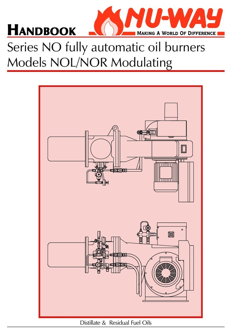
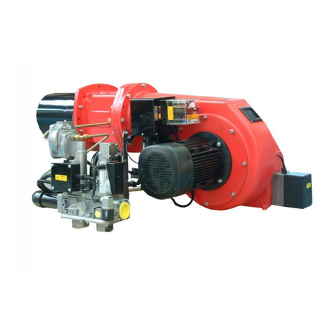
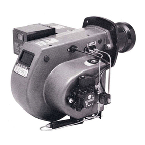
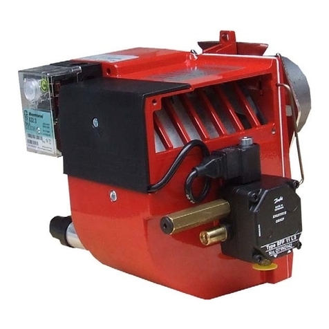
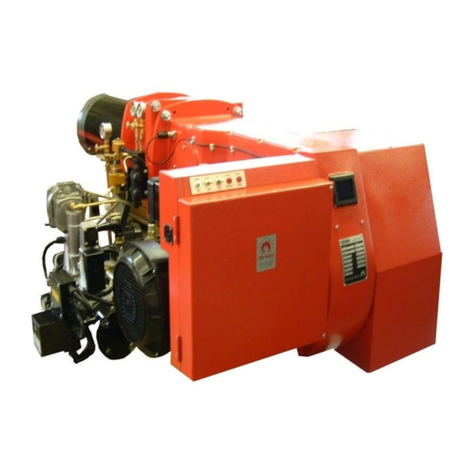
This manual has been produced to enable users
to install, commission and use NO Modulating
burners safely and efficiently. The manual covers
two types of burner: Models NOL distillate (Class
D fuel) oil burners and models NOR residual (Class
E, F & G) oil burners. At each stage the conditions
which should be met and the adjustments and
other actions which should be carried out are de-
tailed and the locations of the various components
and adjustment mechanisms are identified. Where
appropriate, this information is supported by ta-
bles and graphs. Literature on the proprietary com-
ponents used in NO Modulating systems is avail-
able on request.
FF
FF
FEAEA
EAEA
EATURESTURES
TURESTURES
TURES
Developed through extensive field experience in
the UK and overseas markets, the NO Fully modu-
lating series meets the current known test author-
ity requirements in these markets and sets new
standards in efficient and reliable operation. NO
Modulating burners are designed for flange mount-
ing to the appliance front plate and they are deliv-
ered ready to install with a pre-wired packaged
control system and oil pumping or pumping & heat-
ing unit.
Burner Nominal Capacities
NO18 (2 Models) 530 kW 42.0 kg/h
NO35 (2 Models) 940 kW 74.0 kg/h
NO50 (3 Models) 1750 kW 138.0 kg/h
NO60 (3 Models) 2100 kW 165.5 kg/h
NO85 (1 Model) 2432 kW 192.0 kg/h
NO100 (2 Models) 2930 kW 231.5 kg/h
NO125 (3 Models) 3668 kW 290.0 kg/h
NO150 (3 Models) 4396 kW 347.0 kg/h
Controls and Safety Systems
NO Modulating burners are fitted with an auto-
matic sequence / flame failure control and photo-
electric cell for continuous flame supervision. A
combustion air flow control coupled to an oil noz-
zle pressure control system ensures smooth start-
ing and optimum operating effeciency.
Operating Mode
In standard form the NO Fully Modulating burner
can provide a turndown range of up to 3:1.
Fuels
NO burners covered in this manual are designed
to fire distillate and residual fuel oils, which com-
ply with the specifications given in the tables on
page 10. NO burners configured for firing other fuel
grades may be available on request.
SS
SS
SITEITE
ITEITE
ITE CC
CC
C
ONDITIONSONDITIONS
ONDITIONSONDITIONS
ONDITIONS
ANDAND
ANDAND
AND SS
SS
S
ERVICESERVICES
ERVICESERVICES
ERVICES
Flue and Chimney Requirements
It is important that:
The flue pipe from the appliance and the
joint between this flue and the chimney are
sealed to prevent leakage of combustion
products.
The flue pipe from the appliance does not
protrude into the chimney beyond the inside
wall.
The top of the flue or chimney shall be higher
than any roof within a radius of 10 metres.
Checks are made to ensure that the chim-
ney is suitable for oil fired appliances and that
the proposed installation complies with all
Local Authority and other regulations cover-
ing such installations.
If more than one appliance is connected to
a common flue or chimney the cross-section
of this flue or chimney should be adequate
for the total volume of combustion products
from the appliances. It is recommended that
each appliance should be exhausted into a
separate flue.
Plant Room Ventilation
The burner must be supplied with dust free air at
sufficient rates for all firing conditions, in accord-
ance with the appropriate standards.
Existing Appliances
The appliance should be prepared for installation
of the NO burner by thorough cleaning, including
the removal of all adhering tar, scale and dirt. An
inspection should also be carried out to ensure
that the appliance is in good condition. Any doubt
about the appliances suitability for oil firing shall
be referred to the appliance manufacturer.
Combustion Chamber Conditions
The combustion chamber conditions should not
exceed those shown on page 27 of this manual.
