Nuie VSQ2 User manual

SEQUENTIAL SHOWER VALVE
INSTRUCTION MANUAL
PLEASE LEAVE THIS MANUAL WITH THE END USER

CONTENTS
1. INTRODUCTION & SAFETY 1
2. DIMENSIONS 2
3. TECHNICAL DATA 3
4. OPERATION 4
5. COMPONENTS 5
6. SITE INSTALLATION 6-9
7. AFTERCARE 10
8. CALIBRATION 11-13
9. CARTRIDGE REPLACEMENT 14-15
10. FAULT DIAGNOSIS 16
11. INSTALLATION; 17
a) Conditions of use 17
b) Commissioning 18-19
c) Maintenance 19-21
INS005 Rev 1

1
1. INTRODUCTION
This installation guide is for the Thermostatic Sequential Shower Valve.
It covers the installation, maintenance and operation of the Shower
valve. This valve comes either as an Exposed Type Valve or a Concealed
Type Valve. There are different handle and plate types for the valves
depending on which valve was supplied.
The Thermostatic Shower Valve is a sequential valve, for showering
and is thermostatically regulated by a wax element. It is designed to
provide a flow of water at a safe temperature when installed as
described in this manual. The shower valve is suitable for both low and
high pressure installations. The valve is suitable, without modification,
for all types of installation, including pumped gravity systems, mains
pressure and combination boilers.
SAFETY
We recommend that this product is fitted by a fully qualified installer.
The installation must comply with all current water regulations.
Please note: This valve MUST be commissioned on site to suit site
conditions.
In order for this product to operate as designed it must be installed,
commissioned and maintained as stated in this manual.

2
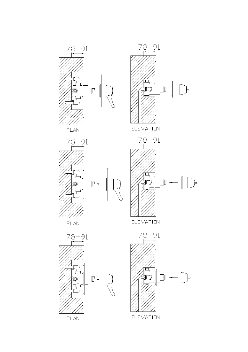
2. DIMENSIONS
ALL DIMENSIONS ARE APPROXIMATE
Exposed:
Concealed:
ALL DIMENSIONS ARE APPROXIMATE

3
3. TECHNICAL DATA
Max Dynamic Pressure: 5 bar
Min Dynamic Pressure: 0.2 bar
Factory Outlet Temperature Setting: 43°C
Minimum Temperature Differential (Mixed water to hot water): 10°C
Temperature Stability: ±2°C
The valve is suitable, without modification, for all types of installation,
including pumped gravity systems, mains pressure and combination
boilers.

4
4. OPERATION
NOTE: THIS DIAGRAM DEPICTS A LEVER TYPE HANDLE BUT THE OPERATING PRINCIPLE IS THE SAME
REGARDLESS OF THE HANDLE. THE ABOVE IS THE RECOMMENDED LEVER ORIENTATION.
The turning angle of the handle is 180 degrees, as illustrated above.
This is from the fully closed position to the fully hot position. The cold
water will get hot gradually from the off position through the 180°
turn.
HOT
OFF

5
5. COMPONENTS
Exposed:
Concealed:

6
6. SITE INSTALLATION
We recommend that this product is fitted by a fully qualified
installer. Please note: This valve MUST be commissioned on
site to suit site conditions and the installation must comply
with all current water regulations.
Please ensure that all components are in the box prior to
fitting.
There are Check Valves and Filters in the Elbows of this
product.
Please ensure that the site conditions are suitable for the
installation of this product. The ideal site conditions can be
found in section 11.
It is recommended that Isolating valves are fitted in conjunction
with this product. These are not supplied.
Please refer to the diagrams in this section prior to installation.
Please plumb the valve in with the hot and cold going to the
correct sides as detailed in the diagrams below. If you have
plumbed it in the incorrectly already, the cartridge can be
reversed (see cartridge replacement section).

7
Exposed Installation:
1. Make sure the pipes are at the correct centres as shown above.
2. Secure the valve to the wall using the screws provided. Be careful
not to damage the screws or the valve in the process.
3. Flush the pipework before connecting the valve. Debris can
prevent the valve working correctly.
4. Connect the pipework using the compression fittings provided.
Check for leaks.
5. The water outlet side can be changed if required.
6. Calibrate and commission the valve as advised.
Note: Please make sure the inlet pipework is plumbed entering the
valve on the correct sides. If the pipes are plumbed the wrong way
around the cartridge can be taken out, turned 180° and replaced. This
prevents the need for the pipework to be changed.
8
Concealed Installation:
A.
B.
C.
Table of contents
Other Nuie Control Unit manuals


Popular Control Unit manuals by other brands

Festo
Festo Compact Performance CP-FB6-E Brief description

Elo TouchSystems
Elo TouchSystems DMS-SA19P-EXTME Quick installation guide

JS Automation
JS Automation MPC3034A user manual

JAUDT
JAUDT SW GII 6406 Series Translation of the original operating instructions

Spektrum
Spektrum Air Module System manual

BOC Edwards
BOC Edwards Q Series instruction manual

KHADAS
KHADAS BT Magic quick start

Etherma
Etherma eNEXHO-IL Assembly and operating instructions

PMFoundations
PMFoundations Attenuverter Assembly guide

GEA
GEA VARIVENT Operating instruction

Walther Systemtechnik
Walther Systemtechnik VMS-05 Assembly instructions

Altronix
Altronix LINQ8PD Installation and programming manual


