manuals.online logo
Brands
  1. Home
  2. •
  3. Brands
  4. •
  5. Nulite
  6. •
  7. Lantern
  8. •
  9. Nulite REGOLO FLANGE User manual

Nulite REGOLO FLANGE User manual

Popular Lantern manuals by other brands

DS Produkte TRF18P0752-1 instructions

DS Produkte

DS Produkte TRF18P0752-1 instructions

Stahl ECOLUX 6610 Series operating instructions

Stahl

Stahl ECOLUX 6610 Series operating instructions

SNOWJOE SUNJOE 24V-LGT500-CT Operator's manual

SNOWJOE

SNOWJOE SUNJOE 24V-LGT500-CT Operator's manual

PRG VARI LITE VL5 Service manual

PRG

PRG VARI LITE VL5 Service manual

Raytec VARIO2 series installation guide

Raytec

Raytec VARIO2 series installation guide

ENSA LEDBT18WS2 installation instructions

ENSA

ENSA LEDBT18WS2 installation instructions

LUG OFFICE LB LED N/T Installation instruction

LUG

LUG OFFICE LB LED N/T Installation instruction

Draper RLEDL19/B instructions

Draper

Draper RLEDL19/B instructions

Green Lighting TRI-SENSOR GL4612LU Assembly & fitting instructions

Green Lighting

Green Lighting TRI-SENSOR GL4612LU Assembly & fitting instructions

Panasonic EY3741B57 operating instructions

Panasonic

Panasonic EY3741B57 operating instructions

Clas Ohlson LCC8T instruction manual

Clas Ohlson

Clas Ohlson LCC8T instruction manual

Coolon WDN-140 manual

Coolon

Coolon WDN-140 manual

shada 1000436 instruction manual

shada

shada 1000436 instruction manual

BEGA 84 036 Instructions for use

BEGA

BEGA 84 036 Instructions for use

BEGA 33 596 Instructions for use

BEGA

BEGA 33 596 Instructions for use

Dale Tiffany GT701162 Assembly instructions

Dale Tiffany

Dale Tiffany GT701162 Assembly instructions

Wagan Brite Nite Pop-Up USB Lantern user manual

Wagan

Wagan Brite Nite Pop-Up USB Lantern user manual

Eaton Crouse-Hinds Pauluhn DLLA M2 Series Installation & maintenance information

Eaton

Eaton Crouse-Hinds Pauluhn DLLA M2 Series Installation & maintenance information

manuals.online logo
manuals.online logoBrands
  • About & Mission
  • Contact us
  • Privacy Policy
  • Terms and Conditions

Copyright 2025 Manuals.Online. All Rights Reserved.

START OF ROW
INSTALLATION
PAGE 3
ROW INSTALLATION
PAGE 4
architectural
INSTALLATION INSTRUCTIONS - LED
REGOLO FLANGE
Instructions and dimensions are subject to change without notification. Instruction sheets on our website supersede all other versions. 2016 Rev. A
10770 East 51stAve, Denver, CO 80239 - Phone (303)287-9646 Fax (303)287-0316
WARNINGS
Risk of electrical shock or fire, disconnect power during installation or servicing. Read all instructions completely before starting installation.
Install and wire in accordance to all national and local codes by a certified electrician. Fixture may be sharp, handle with care. Let fixture
cool before maintenance.
AVERTISSEMENTS
Risque d’électrocution ou d’incendie. Déconnectez l’alimentation durant l’installation ou la maintenance. Lisez attentivement toutes les
instructions avant de commencer toute installation. Faites installer et câbler selon les normes Nationales et Locales par un électricien
certifié. Les installations peuvent être coupantes, à manipuler avec précaution. Laissez refroidir les installations avant une opération de
maintenance.
ADVERTENCIA
Riesgo de descarga eléctrica oun incendio, desconecte la alimentación durante la instalación o servicio. Leer todas las instrucciones
completas antes de empesar la instalación. Instalar y cablear en acuerdo a las reglas nacionales y códigos locales por un electricista
certificado. El accesorio puede estar agudo, agarre con cuidado deje que el acessorio. Enfriar antes de mantenimiento.
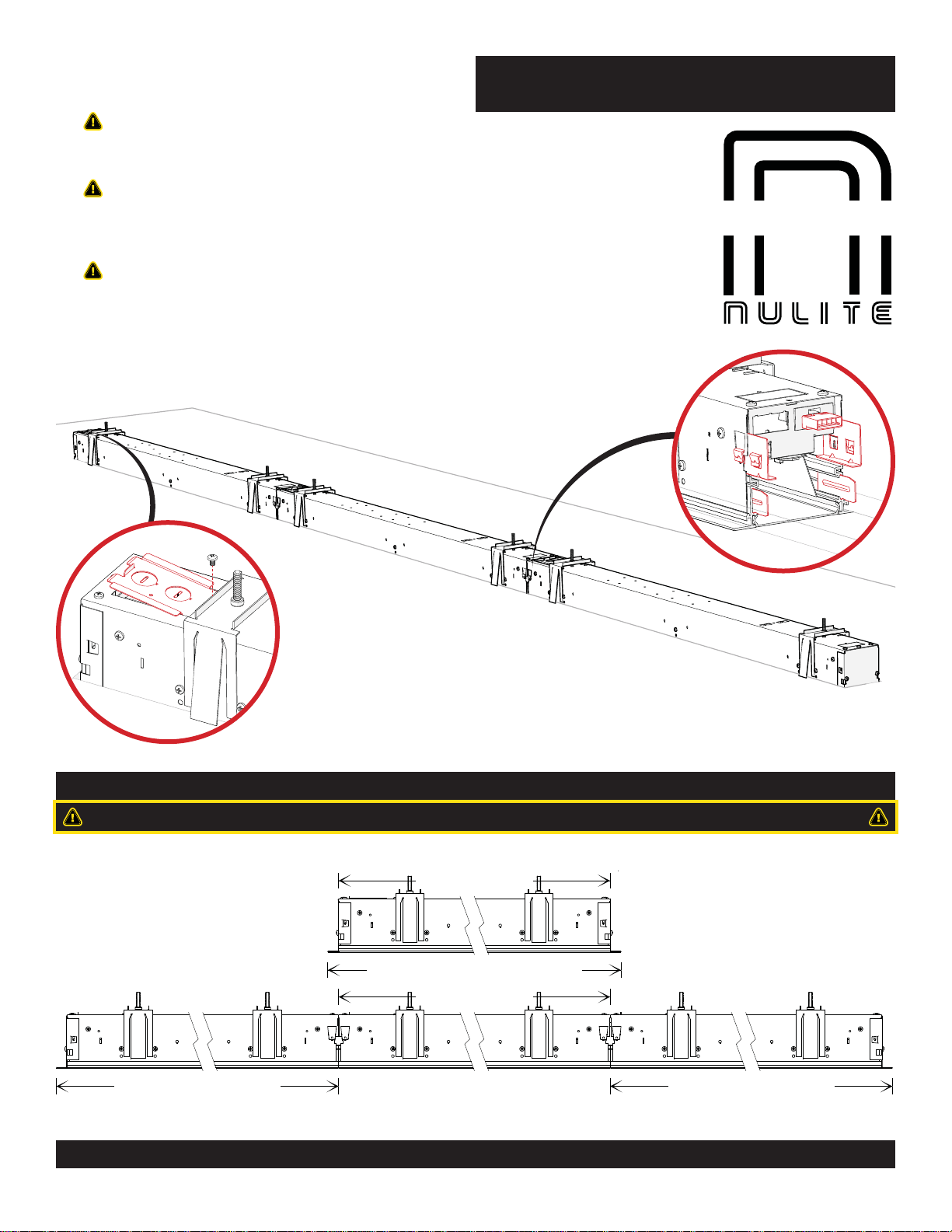
LUMINAIRE LAYOUT
RUN CONFIGURATIONS ARE SPECIFIC TO FACTORY DRAWINGS. CONSULT SUBMITTAL BEFORE BEGINNING INSTALLATION.
LUMINAIRE LENGTH
LUMINAIRE LENGTH
STARTER = LUMINAIRE LENGTH + 3/4” STARTER = LUMINAIRE LENGTH + 3/4”
STANDALONE = LUMINAIRE LENGTH + 1-1/2”
MID LUMINAIRE CONSECUTIVE SECTION
If access to wire way is needed, remove the four screws from
the LED reflector. To remove the reflector completely, separate
the electrical disconnect. Store the reflector in a clean, safe
place during installation or maintenance.
2
OVERVIEW
MAINTENANCE
ALIGNMENTTABS
(BREAK INTO FOUR PIECES)
*NOTE: JOINT
COVER BRACKET
MAY BE DIFFERENT
THAN SHOWN.
JOINT COVER BRACKETS AND
HARDWARE (4) 8-32 X 1/4”
PHILLIPS PAN HEAD SCREWS
RECESSED
JOINING TOOL
HOLE CUTTING TEMPLET TOOL
(NOT TO SCALE)
LENS REMOVALTOOL
INTERMEDIATE POWER
SUPPLY COUPLER
END LUMINAIRE
RIGHT END CAP
STARTER LUMINAIRE
LEFT END CAP
STANDALONE
LUMINAIRE END
CAPS AT EACH END
MID LUMINAIRE
NO END CAPS
Gently insert lens removal tool at one end
of the lens and pull down. Pull the exposed
end down and remove lens. Store the tool in
a safe place.
AVOID TOUCHING THE LED BOARDS.
4
2
LUMINAIRE HOLE CUTTING TEMPLATE:
Two people are required to use the metal
template. A rotary tool with a 1/8” bit is
required to cut the luminaire hole.
3
4” WIDE HOUSING
4” WIDE HOUSING
2” WIDE HOUSING
2” WIDE HOUSING
6” WIDE HOUSING
6” WIDE HOUSING
5-3/4”
2-3/4”
3-3/4”
3/4”
3/4”
3/4”
3/4”
3/4”
3/4”
1-3/8”
1-3/8”
1-3/8”
1-5/16”
1-5/16”
1-5/16”
1-5/16”
1-5/16”
1-5/16”
ACCESS PLATE WITH
TWO 7/8” KNOCK-OUTS OPTIONAL END KNOCK-OUT
(CONSULT FACTORY FOR ACCESS PLATE)
PLAN VIEW OF HOUSING BACK
ROW INSTALLATION - INDIVIDUAL INSTALLATION FOLLOW STEPS 1 THROUGH 7.
5 6
3
24”
2”
1
Snap a center line on the ceiling. Place the first
drywallscrew2”infromthestartoftherow.Space
the screws 24” appart for the entire row length. Make the first cut at the start of row line. The cut
hole length will be 5/8” longer than the row.
Loosen the yoke screws, nearly flush with the
captive nut in yoke. Make sure yoke legs
snap over ceiling.
Insert luminaire into
ceiling hole. Push
up on the yoke
bolts.
ROW LENGTH LINE
START LINE
START LINE
DO NOT DRIVE
THE SCREWS IN
COMPLETELY MARKS THE END OFAROW.
DO NOT CUT THROUGH
TEMPLATE.
START OF ROW
MOUNTING YOKE
9
4
ROW INSTALLATION - INDIVIDUAL INSTALLATION FOLLOW STEPS 1 THROUGH 7.
8
1110
7
Shift the luminaire to the end of the hole.
Secure by tightening the yoke screws
simultaneously (not one at a time).
STARTER
LUMINAIRE
MID LUMINAIRE
ALIGNMENTTABS
INTERMEDIATE
POWER SUPPLY
COUPLER
Align the tabs with the
extrusion slots. Make
sure the power supply
connectors snap together. Install the joiner brackets
to secure the luminaires.
Install the joint cover
brackets with provided
#8X1/4”sheet metal screws.