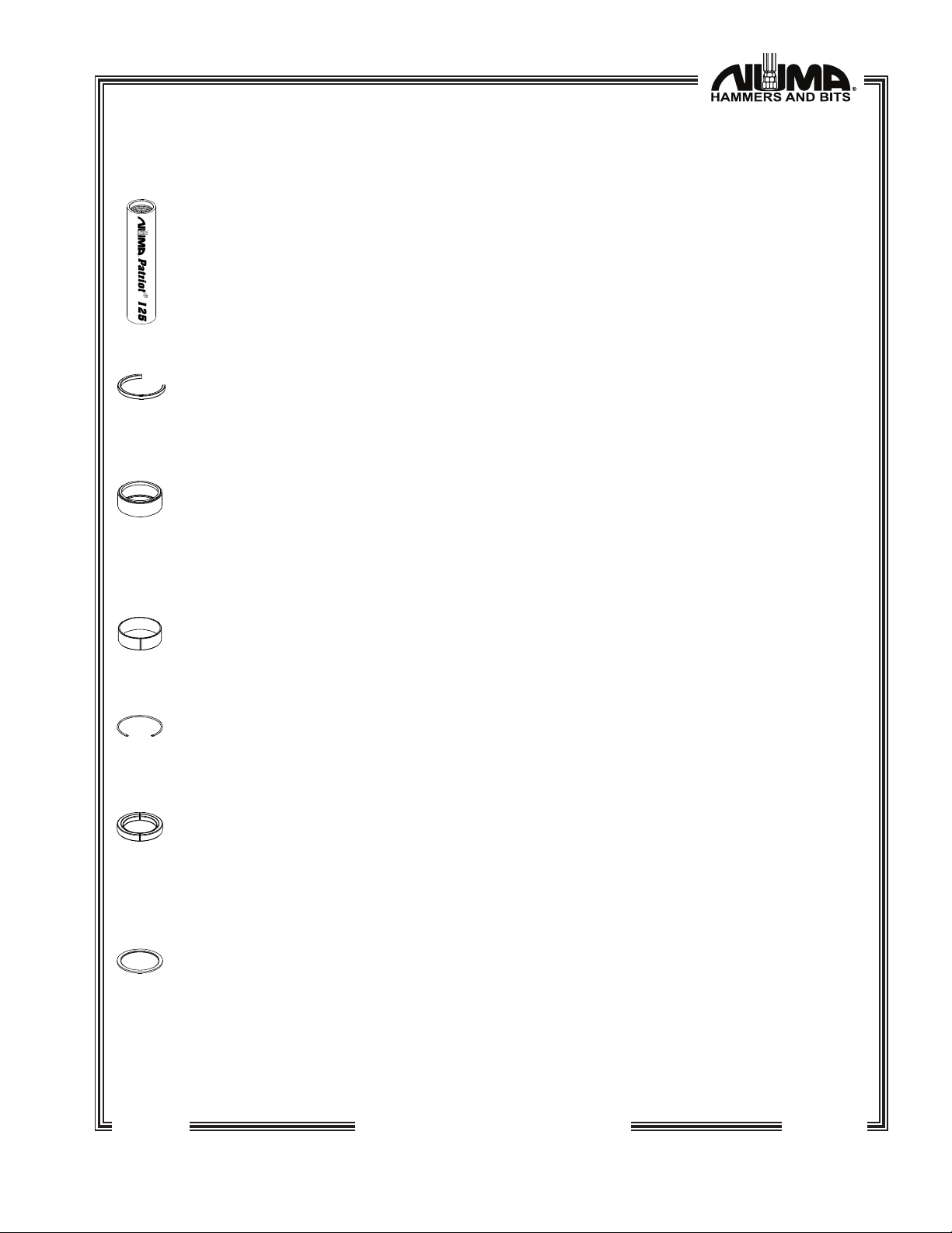
Numa Patriot 125 Maintenance manual

CARE & MAINTENANCE
INSTRUCTIONS
©2023 Numa All Rights Reserved
P.O. Box 348 •646 Thompson Road •Thompson, CT 06277 USA
US Toll Free: (800) 356-NUMA •Tel: (860) 923-9551 •Fax: (860) 923-2617
E-mail: [email protected]
Website: www.numahammers.com
Patents 4,530,408 4,919,221 4,962,822 5,205,363 5,984,021 5,992,537 6,021,856 7,422,074
Patriot
125/125HD


Patriot
125/125HD
TABLE OF CONTENTS
Page
Section I Description ............................................................................1
Functional Description ....................................................................2
1. Backhead ...............................................................................2
2. Pin ............................................................................................2
3. Check Valve - Aluminum .....................................................2
4. Check Valve Spring...............................................................2
5. Feed Tube ...............................................................................2
6. Choke .....................................................................................2
7. Piston .......................................................................................2
8. Case ........................................................................................3
9. Snap Ring ...............................................................................3
10. Bit Bearing...............................................................................3
11. Bit Bearing Bushing (HD model only) ...................................3
12. Bit Bearing Retainer................................................................3
13. Bit Retaining Rings..................................................................3
14. Thrust Washers - Brass............................................................3
15. Chuck......................................................................................4
16. Chuck Bushing .......................................................................4
17. Drive Plates .............................................................................4
Section II Maintenance........................................................................5
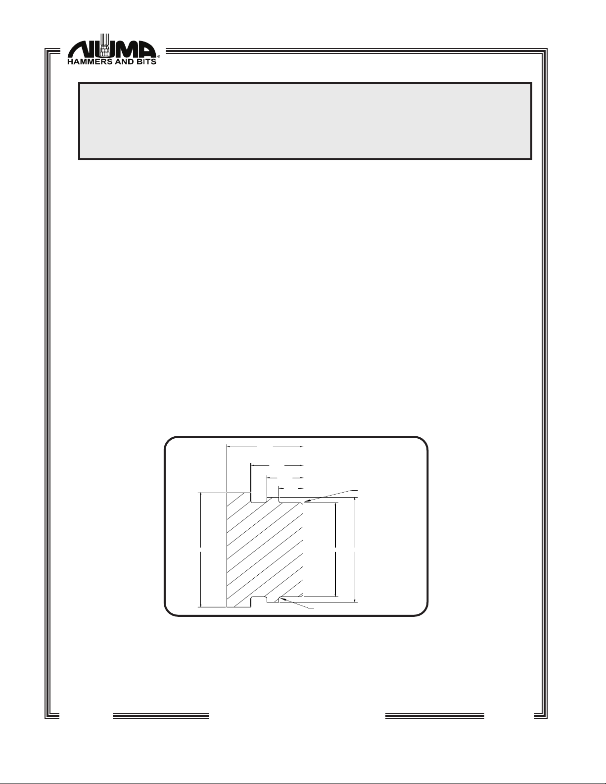
Disassembly .....................................................................................5
Inspection.........................................................................................8
General Assembly.........................................................................11
Hammer Assembly ........................................................................11
Backhead / Feed Tube Assembly ...............................................12
Section III Parts Identication ..........................................................14
Patriot 125/125HD Exploded View ...............................................14
Part Number Reference ................................................................14
Section IV Air Consumption Chart.................................................15
Section V Lubrication..........................................................................16
Section VI Storage................................................................................17
Short Term.......................................................................................17
Long Term .......................................................................................17
Restarting........................................................................................18
Section VII Button Bit Maintenance ..............................................19
General...........................................................................................19
Sharpening .....................................................................................19
Section VIII Patriot 125/125HD Recommended Spares........20

04/23/10
WARRANTIES AND REMEDIES
LIMITED WARRANTY
Numa warrants that the Product will be new and free from defects in material and workmanship
under normal use as contemplated by this Contract for a period of six (6) months from the date of
shipment.
Except for the foregoing warranty, Numa disclaims all warranties and representations wherever
made, including warranties of merchantability, durability, length of service, or tness for a particular
purpose.
Any alteration or modication of the original product without the express written consent of
Numa will void this warranty.
REMEDY
If, during such warranty period, Buyer promptly noties Numa in writing of any defect and
establishes that the above warranty is not met, Numa shall either repair or replace the Product or
credit the customer, as it deems necessary to meet the warranty.
Such repair, replacement, or credit of Product shall constitute complete fulllment of Numa's
obligation under this warranty, and upon the expiration of the original warranty period, all of Numa's
obligations hereunder shall terminate.
LIMITATION OF LIABILITY
Numa shall not be liable to Buyer whether in contract, in tort (including negligence and strict
liability), under any warranty or otherwise, for any special, indirect, incidental or consequential loss
or damage whatsoever, including (without limitation) loss arising from delay, cost or capital and loss
of prots or revenues. The remedies set forth in this Contract are exclusive, and the total cumulative
liability of Numa under this Contract or for any act or omission in connection therewith or related
thereto, whether in contract, in tort (including negligence and strict liability), under any warranty or
otherwise, is limited to the price paid by Buyer for the Product.
The WARNINGS, CAUTIONS and NOTES used throughout the text of this
instruction book are dened as follows:
WARNING A specic procedure or practice that must be strictly followed,
or a specic condition that must be met, to prevent possible
bodily harm.
CAUTION A specic procedure or practice that must be strictly followed,
or a specic condition that must be met, to prevent damage
to the equipment.
NOTE Important supplemental information.
Numa®,Champion, and Patriot
are registered trademarks of Numa.

02/09/23 Page 1
Patriot
125/125HD
SECTION I
DESCRIPTION
GENERAL DESCRIPTION
The Patriot 125/125HD is a valveless, pneumatically operated tool designed to utilize
Numa 12-1/4" to 20" (311 mm to 508 mm) diameter bits in rock formations under a wide range
of operating conditions. The Patriot 125HD utilizes bits from 13" to 20" (331 mm to 508 mm).
The Patriot 125/125HD hammer design incorporates a non-reversible, hardened case.
The single bore design allows for a maximum bore diameter in conjunction with optimum
life against abrasion. The simple design of the Patriot 125/125HD provides performance and
dependability without sacricing tool life.
The Patriot 125/125HD is designed for universal applications using air pressure from 150
PSI to 250 PSI (10.2 Bar to 17.0 Bar) with compressors having capacities of 1300 CFM (614 Litres/
Second) or more. When drilling conditions require supplementary hole cleaning, additional
hole cleaning air can be passed through the hammer by utilizing an interchangeable choke.
All standard hammers shipped from Numa have a blank choke installed. Refer to page 15
for correct choke selection and pages 7 and 12 to facilitate the removal and the installation
of the choke.
Patriot 125/125HD
Weight w/o Bit: P125 1133 lbs. (514 kg)
P125HD 1360 lbs. (618 kg)
Outside Diameter: P125 10-3/4" (273 mm)
P125HD 11-3/4" (298 mm)
Hammer Length:
Shoulder to Shoulder 66-3/4" (170 cm)
Shoulder to Bit Face 75-3/4" (192 cm)
Backhead API Thread 6-5/8 API REG
Table 1-1 General Hammer Specications
12-1/4" (311 mm) 433 lbs. (197 kg) 16" (406 mm) 581 lbs. (264 kg)
12-3/8" (314 mm) 437 lbs. (199 kg) 17-1/2" (445 mm) 619 lbs. (281 kg)
13" (330 mm) 450 lbs. (204 kg) 18" (457 mm) 646 lbs. (293 kg)
14" (356 mm) 509 lbs. (231 kg) 19" (483 mm) 781 lbs. (354 kg)
15" (381 mm) 533 lbs. (242 kg) 20" (508 mm) 833 lbs. (378 kg)
Table 1-2 General Bit Specications
NOTE
Numa 12-1/4" to 20" (311 mm to 508 mm) bits are available in concave face
design with large air ushing holes and chip ways to take advantage of the
Patriot 125/125HD performance. Other sizes may be available upon request.

Page 2 02/09/23
Patriot
125/125HD
FUNCTIONAL DESCRIPTION
1. BACKHEAD
The backhead connects the hammer to the drill rod. It is threaded into the top end of
the case with single start threads and into the drill rod with a standard 6-5/8" API REG
thread. Wrench ats are provided for disassembling. A 11-3/4" (298 mm) HD backhead
is available as an optional extra.
2. PIN
The pin connects and aligns the feed tube assembly into the backhead. It is made
of hardened steel to insure long life.
3. CHECK VALVE - ALUMINUM
The aluminum check valve maintains pressure in the hammer when the air supply has
been shut off. The pressure in the hammer balances the hydrostatic pressure in the
hole thereby preventing contaminants from entering the hammer.
4. CHECK VALVE SPRING
The check valve spring provides tension under the check valve to keep it closed. It
is compressed as the air is turned on.
5. FEED TUBE
The feed tube supplies the main air into the chambers located in the piston. It is
located in the backhead and held in place by a pin.
6. CHOKE
The interchangeable choke is located in the tip of the feed tube and is held in place
with a press t. A set of three chokes is supplied with each hammer. By installing the
correct choke, the hammer can be ne tuned to the compressor package. A hammer
with a plastic feed tube does not utilize a choke. A hole can be drilled in the bottom
tip of the plastic feed tube to facilitate hole cleaning, or pressure control. Use the chart
located on page 15 for proper hole size.
7. PISTON
The piston functions as the only moving part in the hammer, controlling the operational
air cycle. The percussive action of the piston striking the bit transfers the energy
through the bit in order to fracture rock formations. A snap ring inserted in the main
bore prevents the piston from sliding out of the case when the chuck, bit, bit retaining
rings and bit bearing are removed.

02/09/23 Page 3
Patriot
125/125HD
8. CASE
The case is designed to contain the internal parts which make up the hammer
assembly. The case is non-reversible and hardened to resist wear and to extend life in
abrasive conditions. A 11-3/4" (298 mm) OD HD case is also available as an optional
extra.
9. SNAP RING
A snap ring positions the internal parts in the hammer and prevents the piston from
falling out when the chuck, bit retaining rings, bit bearing and bit are removed.
10. BIT BEARING
The bit bearing guides the bit to insure proper alignment between the piston and the
bit. The bit bearing is placed into the chuck end of the case and is located by a
snap ring which is inserted into the main bore. The HD model only has a bit bearing
designed for a bit bearing bushing.
11. BIT BEARING BUSHING (HD model only)
The bit bearing bushing is a nylon insert located in the bit bearing to provide a bearing
surface between the upper bit shank and bit bearing.
12. BIT BEARING RETAINER
The bit bearing retainer sits in a groove in the case and retains the bit bearing.
13. BIT RETAINING RINGS
The bit retaining rings are designed to allow the bit to move between the drilling and
cleaning positions and prevent the bit from coming completely out of the hammer.
The bit retaining rings consist of two matched halves and are held together with the
bit retaining ring o-ring.
14. THRUST WASHERS - BRASS
Two brass thrust washers, one located between the backhead and the case and one
between the chuck and the case, provide for easy disassembly.

Page 4 02/09/23
Patriot
125/125HD
15. CHUCK
The chuck threads into the bottom end of the case. It has internal splines that mesh
with the splines on the bit body to transmit rotation. A 11-3/4" (298 mm) HD chuck is
available as an optional extra.
16. CHUCK BUSHING
The chuck bushing is a nylon insert located in the bottom end of the chuck to provide
a bearing surface between the lower bit shank and chuck.
17. DRIVE PLATES
The plastic drive plates provide wear protection for the splines. They are inserted
between the chuck and the bit. A complete drive plate set is provided with each bit.

02/09/23 Page 5
Patriot
125/125HD
SECTION II
MAINTENANCE
DISASSEMBLY
•If at all possible, the backhead and chuck should be broken loose on the drill rig; this
is much easier than trying to do so after the drill has been removed from the drill rig.
CAUTION
USE CAUTION WHEN HANDLING DOWN THE HOLE HAMMER PARTS. NUMA HAMMER
PARTS ARE MANUFACTURED FROM HARDENED, HEAT TREATED MATERIALS. DROPPING
OR STRIKING THESE PARTS MAY CAUSE SEVERE DAMAGE. STRIKING THE HAMMER
PARTS WITH HAMMERS, CROWBARS OR LIKE INSTRUMENTS WILL VOID THE WARRANTY.
•Maintenance should be performed in a clean environment.
• Tools needed: appropriate hammer lifting device, a hammer stand, chain vise, 2" (51
mm) diameter brass rod, a press, a drift pin and a small screwdriver.
•Clean the outside of the hammer. This will insure a good surface to clamp on.
•With the hammer standing in the vertical postition, using an appropriate lifting device,
unscrew and remove the chuck/bit assembly from the case.
•Remove the bit retaining rings from around the bit.
•Remove the o-ring from the bit retaining rings.
•Remove the drive plates from the bit and chuck splines.
•Remove the brass thrust washer from the chuck.
•Using an appropriate lifting device, unscrew and remove the backhead/feed tube
assembly from the case.
•Place the hammer horizontally on a hammer stand and secure the hammer with a
chain vise.

Page 6 02/09/23
Patriot
125/125HD
CAUTION
THE ACCEPTABLE CLAMPING AREAS START 8" (203 MM) FROM EITHER CASE END, TO
AN ADDITIONAL 5" (127 MM) BEYOND THIS POINT. PLACING THE CHAIN VISE ON
THE AREA OF THE CASE WHERE THE PISTON CYCLES CAN DISTORT THE CASE, RESTRICT
PISTON MOVEMENT AND VOID THE WARRANTY.
•With the case in a horizontal position and using a 2" (51 mm) diameter brass rod, slide
the piston out of the backhead end of the case.
•Removal of the chuck bushing is not necessary for routine maintenance. If necessary,
lay the chuck on its side so that the bit end is facing you. Locate the seam in the
chuck bushing. Insert a screwdriver into the slot in the middle of the seam and pry
the chuck bushing from the under cut. Remove the chuck bushing from the bit end
of the chuck.
•Removal of the bit bearing, bit bearing bushing (in HD model only), and snap ring from
the chuck end of the case is not necessary for routine maintenance. If necessary,
use a small screw driver or similar device to pick out the bit bearing retainer from the
groove. Insert the bit bearing press plate into the backhead end of the case with the
small diameter toward the chuck end. Using a 2" (51 mm) diameter brass rod, slide
the bit bearing press plate to the chuck end of the case until it rests against the bit
bearing. Remove the brass rod. Using a press, apply pressure to the bit bearing press
plate and force the bit bearing and snap ring out of the chuck end of the case. Use
a small screw driver or similar device to pick out the bit bearing bushing from the I.D.
of the bit bearing.
P125/P125HD Bearing Spacer/Press Plate
Figure 2-1
4 3/44 3/4
1 1/21 1/2
2 1/42 1/4
3 1/43 1/4
7 1/27 1/28 3/88 3/89 1/89 1/8
1/8R TYP1/8R TYP
1/8 X 45°1/8 X 45°

02/09/23 Page 7
Patriot
125/125HD
•To disassemble the backhead / feed tube assembly, stand the backhead / feed tube
assembly on a bench, with the API thread facing down.
•Using a drift pin, tap the pin out of the backhead/feed tube assembly.
•Lift the feed tube assembly out of the backhead.
•Remove the feed tube o-ring from the feed tube.
•Removal of the plug and choke are not necessary for routine maintenance. If
necessary, use a 3/8" (10 mm) diameter, 24" (610mm) long rod and tap out the choke
downward, toward the plug. Continue tapping both the plug and choke out of the
feed tube. A hammer with a plastic feed tube does not utilize a choke.
•Remove the brass thrust washer from the backhead.
•Remove the check valve and check valve spring.
•Remove the backhead o-rings from the backhead outside diameter.

Page 8 02/09/23
Patriot
125/125HD
INSPECTION
•All parts should be washed in a clean solvent before they are inspected and
reassembled.
WARNING
USE CLEANING FLUIDS THAT ARE NONFLAMMABLE AND AVOID
BREATHING THE FLUID VAPORS.
•Handle all parts carefully, hardened parts may chip if dropped on a hard surface.
BACKHEAD
•Inspect the threads and pin hole for cracks and burrs.
• Remove all burrs on the thread with a ne le or emery cloth.
•Replace if necessary.
CHECK VALVE - ALUMINUM
•The check valve should be smooth and free from abrasions.
•Replace if necessary.
•Replace the check valve spring if it is worn or broken.
FEED TUBE ASSEMBLY
•Inspect the outside diameters for nicks, burrs and scoring.
•Inspect all makeup surfaces for indentations or nicks caused by wear.
•Remove all minor irregularities with emery cloth.
•Replace if necessary.
PIN
•Inspect pin for scoring or cracks.
•Replace if necessary.

02/09/23 Page 9
Patriot
125/125HD
SNAP RING
•Inspect the snap ring for severe wear indications.
•Remove or round over any sharp edges.
•Replace if necessary.
PISTON
•Inspect the striking face, inside and outside diameters for nicks, scoring and cracks.
•Polish the piston with emery cloth to remove all minor irregularities, cracked pistons
should be replaced.
•Wash the piston thoroughly, inside and out, to remove all emery dust.
CASE
•Inspect the outside diameter for excessive wear or cracks. Inspect the internal case
bore for scoring.
• Remove all minor irregularities with ne honing stones.
•Clearance between the case and piston should not exceed .020" (0.5 mm).
BIT BEARING
•In HD model only, inspect the bit bearing bushing for cracks or irregularities. Replace
if necessary.
•Inspect the inside and outside for nicks and burrs.
•Remove all internal irregularities with a polishing wheel.
•Remove all external irregularities with an emery cloth.
•Clearance between the bit bearing and the bit shank should not exceed .020"
(0.5 mm).
•Replace if necessary.

Page 10 02/09/23
Patriot
125/125HD
BIT RETAINING RINGS
•Inspect for cracks or deformations.
• Remove all irregularities with a le or emery cloth.
•Replace if necessary.
CHUCK
•Inspect the chuck bushing for cracks or irregularities. Replace if necessary.
•Inspect for cracks and burrs.
•For continued use, the outside diameter should be larger than the outside of the case
or the same. Collar length should not be less than 5-1/4" (133 mm).
CAUTION
IF THE COLLAR LENGTH IS LESS THAN 5-1/4" (133 MM) AND THE BIT IS
UNDER LOAD CONDITIONS, CONTACT BETWEEN THE SHOULDER OF
THE BIT RETAINING RINGS AND THE BOTTOM OF THE BIT RETAINING
RING AREA ON THE BIT, COULD CAUSE THE BIT TO FAIL IN THIS AREA.
•Torsional play in the splines should not exceed .200" (5.0 mm).
•Inspect the drive plates. Replace if cracked or worn.
•Replace if necessary.
O-RINGS
•Inspect for damage such as cracks and deformations.
•Replace if necessary.
THRUST WASHERS - BRASS
•Inspect for damage such as cracks and deformations.
•Replace if necessary.

02/09/23 Page 11
Patriot
125/125HD
GENERAL ASSEMBLY INSTRUCTIONS
•Assembly should be performed in a clean environment.
•All parts should be cleaned thoroughly and wiped dry before assembly.
•Oil all parts by hand using Rock Drill Oil to insure easy assembly.
•Coat all thread connections with a thread compound to allow joints to thread easily.
HAMMER ASSEMBLY
•Using the 2" (51 mm) brass rod, install the thick snap ring into the groove, located in
the chuck end of the case.
•In HD model only, insert the bit bearing bushing into the bit bearing.
•Press the bit bearing in the case, until it seats against the snap ring.
•Install the round bit bearing retainer in the groove at the shoulder of the bit bearing.
•Install the thrust washer (1/8" thick on non-HD model) against the shoulder of the chuck
threads and insert the chuck bushing in the ID under cut of the chuck. With the bit face
down, place the chuck over the top of the bit. Align the splines and lower the chuck
completely onto the bit. Rotate the chuck counterclockwise until the splines meet and
insert the drive plates between the chuck and the bit splines. See Figure 2-3.
•Place the bit retaining rings, with the bit retaining ring o-ring installed, over the bit
shank and on top of the chuck.
N125/P125 Drive Plate Positioning as Viewed from Top
Figure 2-3.

Page 12 02/09/23
Patriot
125/125HD
BACKHEAD / FEED TUBE ASSEMBLY
•Place the backhead on the bench with the API threads facing down. Install the
backhead o-rings into the grooves located on the thread diameter.
•Place the check valve and check valve spring in the backhead.
•Place the feed tube o-ring into the groove located just under the pin hole of the feed
tube.
•Drop the choke into the feed tube and using the small rod, tap the choke in place.
A hammer with a plastic feed tube does not utilize a choke.
•Using a drift pin, tap the plug into the feed tube until it seats against the shoulder.
• Using a rubber mallet, tap the feed tube into the backhead, aligning the hole in the
feed tube with the hole in the backhead.
•Using a rubber mallet, tap the pin into the hole.
•Place the thrust washer (1/2" thick on non-HD model) over the backhead threads until
it rests against the backhead shoulder.
HAMMER ASSEMBLY CONTINUED
•Place the hammer horizontally on a hammer stand and secure with a chain vise.
CAUTION
THE ACCEPTABLE CLAMPING AREAS START 8" (203 MM) FROM EITHER CASE END, TO
AN ADDITIONAL 5" (127 MM) BEYOND THIS POINT. PLACING THE CHAIN VISE ON
THE AREA OF THE CASE WHERE THE PISTON CYCLES CAN DISTORT THE CASE, RESTRICT
PISTON MOVEMENT AND VOID THE WARRANTY.
•Slide the piston in the backhead end of the case. Push the piston all the way to the
chuck end. The piston should ride in the case very smoothly.
•Using an appropriate lifting device, stand the hammer case up in a vertical position
with the chuck end on the ground.
•Using an appropriate lifting device, lower the backhead / feed tube assembly into
the case. Thread the backhead / feed tube assembly into the case until it shoulders
up.
•Using an appropriate lifting device, lower the hammer assembly over the chuck/bit
assembly. Thread the chuck/bit assembly into the case and hand tighten. The chuck
should shoulder against the thrust washer and case, with no gap present.

02/09/23 Page 13
Patriot
125/125HD
CAUTION
DUE TO CLOSE TOLERANCES BETWEEN THE PATRIOT 125/125HD INTERNAL PARTS
AND THE CASE, NUMA CAN NOT ACCEPT RESPONSIBILITY FOR DAMAGE CAUSED
BY WELDING ON THE CASE OD. WELDING ON THE CASE CAN CREATE DISTORTION,
CAUSE PREMATURE FAILURE AND VOID THE WARRANTY. CONTACT NUMA FOR
SPECIAL INSTRUCTIONS IF WELDING THE CASE BECOMES UNAVOIDABLE.

Page 14 02/09/23
Patriot
125/125HD
Backhead 6-5/8 Reg Pin
015966 (1)
016108 (1) - HD
Backhead O-Ring
005867 (2)
Pin
015904 (1)
Thrust Washer - Brass
015155 (1)
011412 (2) - HD
Check Valve
018121 (1)
Check Valve Spring
018122 (1)
Feed Tube Assembly
015967 (1)
015997 (1) - HD*
Plastic Feed Tube
Plug
011419 (1)
Choke
005564 (1)
Feed Tube
015968 (1)
015998 (1) - HD Plastic
Feed Tube O-Ring
015809 (1)
Piston
008171 (1)
* NOTE: A hammer with a
Plastic Feed Tube does not
utilize a choke.
HAMMER ASSEMBLY #015970
CFSR #015971 / NTR #018690 / HD #016107
Figure 3-1
SECTION III
PARTS IDENTIFICATION
EXPLODED VIEW
Case
011969 (1)
011408 (1) - HD
Snap Ring
008172 (1)
Bit Bearing
008186 (1)
Bit Bearing - HD Only
010055 (1) - HD
Bit Bearing Bushing
010056 (1) - HD Only
Bit Bearing Retainer
008190 (1)
Bit Retaining Rings
008189 (1)
Bit Retaining Rings
O-Ring
005867 (1)
Thrust Washer - Brass
008175 (1)
011412 (2) - HD
Chuck
008187 (1)
015559 (1) - CFSR
013320 (1) - NTR
011409 (1) - HD
Chuck Bushing
008191 (1)
011416 (1) - HD

02/09/23 Page 15
Patriot
125/125HD
SECTION IV
AIR CONSUMPTION CHART
PATRIOT 125
6.9 10.3 13.6 17.2 20.4 24.1
800
1600
2400
3200
4000
CFM
4800
100 150 200 250 300 350
378
756
1132
1512
1888
L/SEC
2265
4
3
2
1
DRILL PRESSURE (BAR)
DRILL PRESSURE (PSI)
3/8 (9.5mm) CHOKE
1/2 (12.7mm) CHOKE
4
3
SOLID CHOKE
1/4 (6.4mm) CHOKE
1
2
* Operation Above 250 PSI (17 BAR) Is Not Recommended.

Page 16 02/09/23
Patriot
125/125HD
SECTION V
LUBRICATION
The Patriot 125/125HD hammer requires a continuous supply of the correct type Rock
Drill Oil. The Patriot 125/125HD hammer consumes at least 5 quarts (5 litres) of Rock Drill Oil
per hour in order to maintain adequate lubrication. See table 5-1 for recommended Rock
Drill Oil.
Medium SAE 30 Heavy SAE 50
Shell Air Tool Oil S2 A 150 Air Tool Oil S2 A 320
Texaco / Caltex Rock Drill Lube 100 Rock Drill Lube 320
Chevron Vistac 150 Vistac 320
Conoco Conoco 150 Conoco 320
Numa Bio Blend RDP 150 RDP 320
Table 5-1
Recommended Rock Drill Oil
CAUTION
ROCK DRILL OILS ARE THE ONLY ACCEPTABLE LUBRICANTS. SAE 50 ROCK
DRILL OIL SHOULD BE USED IN AMBIENT TEMPERATURES OF 80° FAHRENHEIT
(27° CELSIUS) OR HIGHER. CONTACT NUMA FOR ACCEPTANCE OF
ALTERNATIVE ROCK DRILL LUBRICANTS.
CAUTION
THE PATRIOT 125/125HD HAMMER, AS WITH ANY MACHINE, REQUIRES
CONTINUOUS LUBRICATION. THE FAILURE TO SUPPLY ADEQUATE
LUBRICATION TO THE HAMMER CAN CAUSE PREMATURE FAILURE AND MAY
VOID THE WARRANTY.
This manual suits for next models
1
Table of contents
Other Numa Power Hammer manuals
Popular Power Hammer manuals by other brands

Sumake
Sumake ST-2231/R quick start guide

Scheppach
Scheppach 7906100716 Translation of original operating manual

Benner-Nawman
Benner-Nawman BNH-1770 Operator's manual

Hitachi Koki
Hitachi Koki H 65SB Handling instructions

Würth
Würth MH 16-XE Translation of the original operating instructions

RAMSET
RAMSET DynaDrill 585 Operator's manual

Scheppach
Scheppach 5808201985 Translation from original manual

Black & Decker
Black & Decker PRO Series manual

DeWalt
DeWalt D25501 instruction manual

Hitachi
Hitachi H 25PV Handling instructions

EINHELL
EINHELL TC-DH 1600/1 Original operating instructions

Black & Decker
Black & Decker 5019K instruction manual