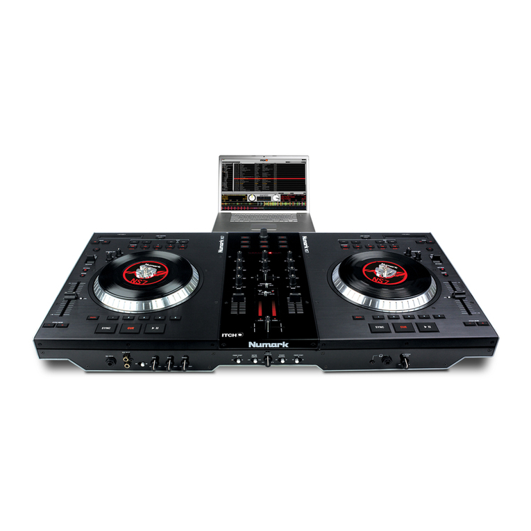
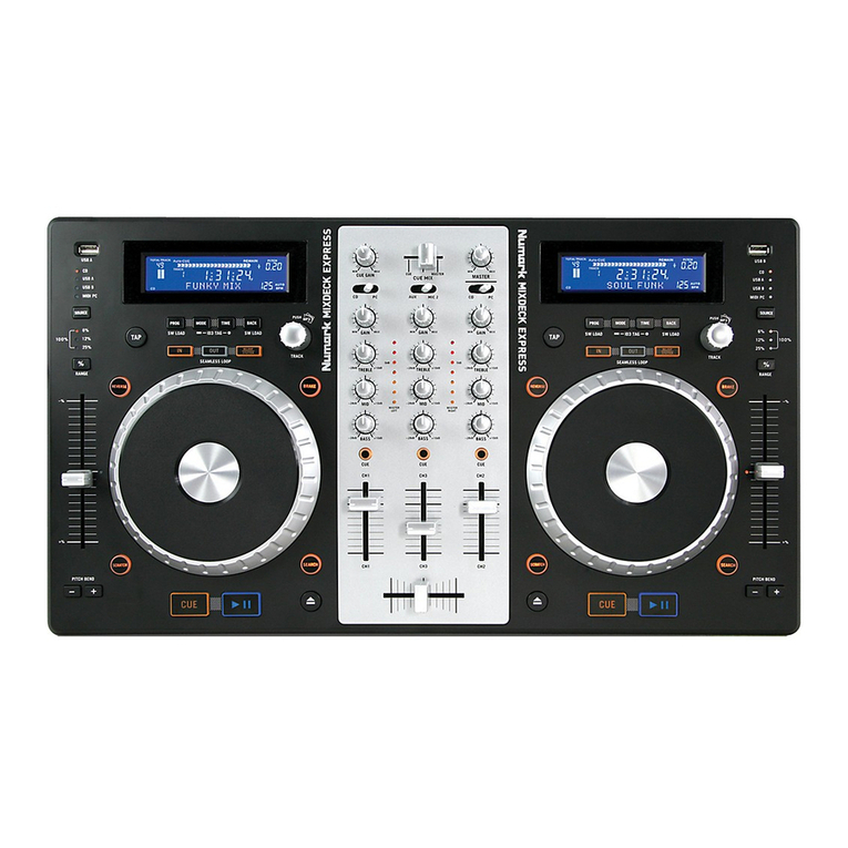
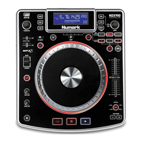
Numark NS7FX User manual

Confidential Numark Service Manual
Numark
NS7FX
(NK06 + NK16)
Service Manual
Rev. 2
2010.05.18
The information in this document contains privileged and confidential information. It is intended
only for the use of those authorized by Numark. If you are not the authorized, intended recipient,
you are hereby notified that any review, dissemination, distribution or duplication of this document
is strictly prohibited. If you are not authorized, please contact Numark and destroy all copies of
Copyright Numark Industries
ATTENTION!
THIS DOCUMENT CONTAINS SENSITIVE
PROPRIETARY INFORMATION.
ALL RECIPIENTS MUST HAVE A CURRENT
NON-DISCLOSURE AGREEMENT ON FILE
WITH NUMARK INDUSTRIES.
DO NOT MAKE ILLEGAL
COPIES OF THIS DOCUMENT

Confidential Numark Service Manual
PREFACE
This document is intended to assist the service technician in the operation, maintenance and
repair of the Numark device. Together with the User Reference Manual, this document provides
a complete description of the functionality and serviceability of the Device. Any comments or
suggestions you may have pertaining to the document are welcome and encouraged.
READ THIS!
In addition to any purchase price that Numark may charge as consideration for Numark selling or
otherwise transferring this service manual (“Manual”) to you, if you are not a service and repair
facility (“Service Center”) authorized by Numark in writing to be an authorized Service Center,
Numark sells or transfers the Manual to you on the following terms and conditions:
Only Service Centers authorized by Numark in writing are authorized to perform service and
repairs covered by an Numark warranty (if any), and transfer of the Manual to you does not
authorize you to be an authorized Service Center. Therefore, if you perform, or if the Manual
is used to perform, any service or repairs on any Numark product or part thereof, any and
all warranties of Numark as to that product and any service contract with Numark for that
product shall be voided and shall no longer apply for such product, even if your services
or repairs were done in accordance with the Manual.
All service or repairs done by you or with reference to the Manual shall be solely your
responsibility, and Numark shall have no liability for any such repairs or service work. All such
service or repairs are performed at the sole risk of the person performing the service or
repairs. You agree that all such work will be performed in a competent, professional and safe
manner at all times and to indemnify and fully hold Numark and its successors and assigns
harmless in the event of any failure to so perform.
Your purchase of the Manual shall be for your own ultimate use and shall not be for purposes of
resale or other transfer.
As the owner of the copyright to the Manual, Numark does not give you the right to copy the
Manual, and you agree not to copy the Manual without the written authorization of Numark.
Numark has no obligation to provide to you any correction of, or supplement to, the Manual, or
any new or superseding version thereof.
Numark shall have the right to refuse to sell or otherwise transfer repair parts or materials to you
in its sole discretion. You shall not use, sell or otherwise transfer spare or replacement parts
supplied by Numark to you (i) to repair or be used in products manufactured for or by third parties
or (ii) to any third parties for any purpose.
You shall not make any warranties or guarantees with respect to the products of Numark or the
use thereof on behalf of Numark or in your own name.
The foregoing describes the entire understanding related to sale or transfer of the Manual to you,
and no other terms shall apply unless in a writing signed by an authorized representative of
Numark.
All Trademarks are property of their respective companies.
Confidential Numark Service Manual
WARNINGS
TO REDUCE THE RISK OF ELECTRIC SHOCK OR FIRE, DO NOT EXPOSE
THIS PRODUCT TO WATER OR MOISTURE.
The arrowhead symbol on a lightning flash inside a triangle is
intended to alert the user to the presence of uninsulated "dangerous
voltage" within the enclosed product which may be of sufficient
magnitude to constitute a risk of electric shock to persons.
The exclamation point inside a triangle is intended to alert the user
to the presence of important operating, maintenance and servicing
instructions in the literature which accompanies the product.
REPAIR BY ANY PERSON OR ENTITY OTHER THAN AN AUTHORIZED
NUMARK SERVICE CENTER WILL VOID THE NUMARK WARRANTY.
PROVISION OF THIS MANUAL DOES NOT AUTHORIZE THE RECIPIENT TO
COMPETE WITH ANY NUMARK DISTRIBUTOR OR AUTHORIZED REPAIR
SERVICE CENTER IN THE PROVISION OF REPAIR SERVICES OR TO BE
OR MAKE REPAIRS AS AN AUTHORIZED SERVICE CENTER.
ALL REPAIRS DONE BY ANY ENTITY OTHER THAN AN AUTHORIZED
NUMARK SERVICE CENTER SHALL BE SOLELY THE RESPONSIBILITY OF
THAT ENTITY, AND NUMARK SHALL HAVE NO LIABILITY TO THAT ENTITY
OR TO ANY OTHER PARTY FOR ANY REPAIRS BY THAT ENTITY.
Regarding the Power Supply Fuse
CAUTION: The product under service may employ the use of a
replaceable fuse. Danger of fire or electrocution if fuse is incorrectly
replaced. Replace with only the same type or equivalent type
recommended by the equipment manufacturer.
Regarding the Internal Battery
CAUTION: The product under service may employ the use of a
internal battery. Danger of explosion if battery is incorrectly
replaced. Replace only with the same or equivalent type
recommended by the manufacturer. Dispose of used batteries
according to the manufacturer's instruction.

Confidential Numark Service Manual
Safety Instructions
Carefully read the applicable items of the operating instructions and these safety suggestions
before using this product. Use extra care to follow the warnings written on the product itself and in
the operating instructions. Keep the operating instructions and safety suggestions for reference in
the future.
1. Power Source. The product should only be connected to a power supply which is described
either in the operating instructions or in markings on the product.
2. Power Cord Protection. AC power supply cords should be placed such that no one is likely to
step on the cords and such that nothing will be placed on or against them.
3. Periods of Non-use. If the product is not used for any significant period of time, the product's
AC power supply cord should be unplugged from the AC outlet.
4. Foreign Objects and Liquids. Take care not to allow liquids to spill or objects to fall into any
openings of the product.
5. Water or Moisture. The product should not be used near any water or in moisture.
6. Heat. Do not place the product near heat sources such as stoves, heat registers, radiators or
other heat producing equipment.
7. Ventilation. When installing the product, make sure that the product has adequate
ventilation. Improperly ventilating the product may cause overheating, which may damage the
product.
8. Mounting. The product should only be used with a rack which the manufacturer
recommends. The combination of the product and rack should be moved carefully. Quick
movements, excessive force or uneven surfaces may overturn the combination which may
damage the product and rack combination.
9. Cleaning. The product should only be cleaned as the manufacturer recommends.
10. Service. The user should only attempt the limited service or upkeep specifically described in
the operating instructions for the user. For any other service required, the product should be
taken to an authorized service center as described in the operating instructions.
11. Damage to the Product. Qualified service personnel should service the unit in certain
situations including without limitation when:
a. Liquid has spilled or objects have fallen into the product,
b. The product is exposed to water or excessive moisture,
c. The AC power supply plug or cord is damaged,
d. The product shows an inappropriate change in performance or does not operate
normally, or
e. The enclosure of the product has been damaged.

SPECIFICATION
FUNCTION
1. GAIN TRIM – Adjusts the pre-fader, pre-EQ audio level of the corresponding channel in the software.
2. CHANNEL TREBLE – Adjusts the high (treble) frequencies.
3. CHANNEL MID – Adjusts the mid-range frequencies.
4. CHANNEL BASS – Adjusts the low (bass) frequencies.
5. CHANNEL FADER – Adjusts the audio level on the corresponding channel in the software.
6. CROSSFADER – Blends audio between the channels assigned to the left and right side of the crossfader.
7. MASTER VOLUME – Adjusts the output volume of the Program Mix.
8. BOOTH VOLUME – Adjusts the output volume of the BOOTH OUTPUT mix.
9. HEADPHONE MIX – Blends the pre-fader audio playing on Channels 1 and 2. Sliding this to the left plays Channel 1. Sliding to the right plays
Channel 2.
10. HEADPHONE MODE – Selects the audio that is sent to the headphones. Switch it to “MASTER” to hear the Program Mix. Switch it to “CH1
CH2” to hear a mix of Channels 1 and 2 in the headphones.
11. MASTER OUTPUT (BALANCED) – Connect this low-impedance XLR output to a PA system or powered monitors The level of this output is
controlled with the MASTER knob on the top panel.
12. MASTER OUTPUT (RCA) – Use standard RCA cables to connect this output to a speaker or amplifier system The level of this output is
controlled by the MASTER knob on the top panel.
13. BOOTH OUTPUT (RCA) – Use standard RCA cables to connect this output to a booth monitoring system The level of this output is controlled
by the BOOTH knob on the top panel.
14. SYNC – Automatically matches the corresponding Deck’s tempo with the other Deck’s tempo.
15. RELOOP – Press this to jump to the start of the loop and enable it. If the Deck is already looping when you press it,
Pointer will jump to the start
of the loop and continue. If no loop is set, nothing will happen.
16. 1/2 X – Press this to halve the length of the selected loop.
17. 2 X – Press this to double the length of the selected loop.
18. STRIP SEARCH – The length of this strip represents the length of the entire track. Place your finger on a point along this sensor to jump to that
point in the track. (If you want to scroll through a track, we recommend using your computer rather than running 'your finger along the strip.)
19. TAP – Tap this button at the same tempo as the track to help the software detect a more accurate BPM reading.
20. CRATES – Press this to move the selector to the Crates Panel in the software
21. Activates Effects in Itch
22. Basic controls, mirroring those found in NK14
23. Master BPM tap for ITCH
SERVICE MANUAL
MODEL:NS7FX

24. FX Parameter. 360 pots with 11-LED position indicator ring
25. FX Select. 20 position encoder with push switch. Relative CC message
26. FX Wet/Dry. 30mm slide pot
27. MASTER BPM TAP: Tapping this enters the BPM for master FX processing
STANDARD
1. MaxMSP test program for production Line
2. AP fest specification
RCA Balance Output
Voltage AC 100V~240V 50~60Hz
MASTER:3.5
0.5V
Volume BOOTH:3.5
0.5V
BALANCED:12
2V
Distortion defection 0.02% below
S/ N 96dBr upward
Separation 94dBr upward
F/R 20~20KHz
0.5dB
1. When test is in progress , gain on Input and headphone is set at Max. volume.
Headphone : UN Balanced:
2. 300mV 1KHz Sin wave form is input to left plug of Aux Input
Volume 7V
1V
S/N 85dBr upward
Distortion defection 0.05% below
F/R 20~20KHz
1dB

DISASSEMBLY PROCEDURES
(A) REMOVAL 42 PCS OF SCREWS BEFORE REMOVE THE BOTTOM CHASSIS.
(A) REMOVE THE 1 PC NUT.
(B) REMOVE THE 4 PCS OF SCREWS.
(C) REMOVE THE 4 PCS CONNECTORS BEFORE REMOVAL OF PHONE PCB.
(D) REMOVE THE 3 PCS OF SCREWS.
(E) REMOVE THE 1 PC CONNECTORS BEFORE REMOVAL OF XFADER PCB.
(F) REMOVE THE 1 PC NUT.
(G) REMOVE THE 5 PCS OF SCREWS.
(H) REMOVE THE 1 PC CONNECTORS BEFORE REMOVAL OF INPUT PCB.

(A) REMOVE THE 4 PCS OF SCREW.
(B) REMOVE THE 4 PCS CONNECTOR.
(C) REMOVE THE 5 PCS SCREW BEFORE REMOVAL OF MAIN PCB.
(D) REMOVE THE 8 PCS OF SCREWS.
(E) REMOVE THE 6 PCS CONNECTOR BEFORE REMOVAL OF MOTOR PCB(L&R).
(F) REMOVE THE 4 PCS OF SCREW.
(G) REMOVE THE 2 PCS CONNECTOR BEFORE REMOVAL OF SWITCH POWER.
(H) REMOVE THE 3 PCS OF SCREW.
( I ) REMOVE THE 3 PCS CONNECTOR BEFORE REMOVAL OF POWER PCB.

(A) REMOVE THE 3 PCS OF VR KNOB.
(B) REMOVE THE 19 PCS OF SCREW.
(C) REMOVE THE 3 PCS OF BRASS STANDOFF.
(D) REMOVE THE 4 PCS CONNECTOR BEFORE REMOVAL OF FUNTION PCB(L).
(E) REMOVE THE 12 PCS OF KNOB AMD 7 PCS NUT.
(F) REMOVE THE 5 PCS OF SCREW.
(G) REMOVE THE 4 PCS OF BRASS STANDOFF
(H) REMOVE THE 4 PCS CONNECTOR BEFORE REMOVAL OF MIXER PCB.
( I ) REMOVE THE 3 PCS OF VR KNOB.
(J ) REMOVE THE 4 PCS OF BRASS STANDOFF.
(K) REMOVE THE 3 PCS OF BRASS STANDOFF.
(L) REMOVE THE 19 PCS OF SCREW.
(M) REMOVE THE 4 PCS CONNECTOR BEFORE REMOVAL OF FUNTION PCB(R).

! !
(A) REMOVE THE 4 PCS OF VR KNOB
(B) REMOVE THE 8 PCS SCREW BEFORE REMOVAL OF FRONT PANEL.
(C) REMOVE THE 2 PCS SCREW.
(D) REMOVE THE 1 PC CONNECTOR BEFORE REMOVAL OF CROSS FADER PCB.
(E) REMOVE THE 4 PCS OF SCREW.
(F) REMOVE THE 2 PCS CONNECTOR BEFORE REMOVAL OF FADER PCB.(L&R)
(G) REMOVE THE 4 PCS OF SCREW.
(H) REMOVE THE 1 PC CONNECTOR BEFORE REMOVAL OF METER PCB.
!


DISASSEMBLY PROCEDURES
1. REMOVAL OF CABINET AND BOTTOM CHASSIS. (Fig1
)
(A) REMOVAL 6 PCS OF VR KNOB.
(B) REMOVAL 2 PCS OF E RIN.
(C) REMOVAL 2 PCS OF HOLDER SCREW.
(D) REMOVAL 13 PCS OF SCREWS BEFORE REMOVAL OF BOTTOM CHASSIS.


LEVEL
P/N DESCRIPTION QTY REF
0.1 AL4-71-0016 CABLE USB RF CHOKE 2.0 1
0.1 BC1015025000 BUBBLE PAD 1
0.1 BC1030008520 BUBBLE PAD 1
0.1 BC1035012020 BUBBLE PAD 1
0.1 CB513N053 SEPARATE WALL 2
0.1 CB300GMAR22 CD SLEEVE 1
0.1 CGNK616513MAR01 INNER BOX 1
0.1 CL22001 WIRE TIE 2
0.1 CTCKD313MAR01 CARTON 1
0.1 CTCKD313MAR02 PLATTER BOX 2
0.1 CTNK616513MAR01 CARTON 1
0.1 GEMAR61 POSTER 1
0.1 LAC62MAR367 BAR CODE LABEL 2
0.1 LAC67YAH261 STICKER 8MM GREEN 1
0.1 LAC42MAR325 LABEL 1
0.1 NM1104414 CLEANING CLOTH 1
0.1 NM1104420 VELVET CARPET 1
0.1 NM1105101 Slipmat 2
0.1 OPNK14MAR03 OPERATION MANUAL 1
0.1 PE060930BO POLYBAG 1
0.1 PE230370402B07 POLYBAG 230*370MM 2
0.1 PLNK0601 PLOYFOAM 1
0.1 PLNK0603 PLOY FOAM 1
0.1 PLNK0604 PLOY FOAM 1
0.1 PLNK0605 FOLY FOAM 1
0.1 SC0404SIBI SCREW 2
0.1 SD1000900 SOFT SHEET 1
0.1 TSNK616 SOFTWARE CD 1
LEVEL
P/N DESCRIPTION QTY REF
2 CA050318001 USB Cable 1800mm A-Type /Conne 1 16
2 ERE74 4MM E RING 2 14
2 LA62GMN37 DATE LABEL 1 17
2 LAC22MAR388 S/N BAR CODE LABEL 1 18
2 LAC51MAR356 WARNING LABEL 1 20
2 LAC63MAR395 SAFETY LABEL(ETL) 1 22
2 MT1101822 METAL PLATE 2 8
2 MT11044104 HOLDER SCREW 2 4
2 MT113007001 FRONT PANEL PAINITING & PRINTI 1 7
2 NM1104418 VELVET CARPET 1
2 NP211MAR109 NAME PLATE 2 6
2 PLNK1601 POLYFOAM 2
2 PT0710620801 KNOB 2 2
2 PT1110613601 KNOB 2 1
2 PT1110613701 KNOB 2 5
2 PT11106178 VR KNOB PAINITING ABS+ABS 2 3
2 PT1110619633 KNOB (F/X)LASER 2 10
NK616MAR01 BOM
NK16MAR01 BOM

2 PT1110619634 KNOB(TAP)LASER 2 11
2 PT113020601 CABINET PRINTING 1 9
2 PT113032101 BOTTOM CHASSIS PRINTING 1 15
2 RU1104412 FOOT 2 21
2 RU1130714 FOOT STAND 2 19
2 SC0314FBBI SCREW 15 13
2 SD10055005 SOFT SHEET 1
0.1 TWMT1104410502 HOLDER PLATE ASS'Y 1
2 GELE-60HP GREASE 4
2 MT1104410502 HOLDER PLATE 1
2 MT1104498 SCREW 2
2 NP311MAR92 LOGO 2
2 PT11044145 HOLDER 4
0.1 TWMT110446201 METEL PLATE ASS'Y 2
2 BANK0601 Vinyl PUNCH 2 2-3
2 MT110446201 HOLDER PLATE 2 2-1
2 MT110446301 45 RPM ADAPTER 2 2-2
2 MT1104487 HOLDER 2 2-5
2 SC0404SIBI SCREW 2 2-6
2 SC2605FIBI SCREW 6 2-4
0.1 TWMT112023302 METAL PLATE ASS'Y 2
2 MT112023301 METAL PLATE 2
2 RU1104410 FOOT 2
2 SC0308FIBI SCREW 4
2 TWPT1104414101 HOLDER ASS'Y 2
2 TWPC09C05001 CONTROL PCB ASS'Y 1 12
3 AL0-09-0044 VARIABLE RESISTOR 2 P2,3
3 AL0-17-1221 RESISTOR 4X2201/10W 4 R14,37,40,46
3 AL2-51-4401 TRANSISTOR 2N4401 2 Q1,3
3 AL2-61-7223 IC NJU7223DL1-33 1 U4
3 AL2-63-0014 IC 74AHCT14 1 U2
3 BALED3X5C LED HOLDER 4 (LED15~18)
3 CS102K5003X7R CERAMIC 1000P (SMD) 8 C18,21,25,37~41
3 CS103K5003X7R CERAMIC 0.01UF (SMD) 6 C4,9,10,14,15,32
3 CS104K5003X7R CERAMIC 0.1UF (SMD) 25 C1,3,5,8,12,13,16,17,19,20,24,28,31,35,36,42~45,47~5
1,56
3 CS105K1003X5R CERAMIC 1UF (SMD) 1 C6
3 CS180J5003NPO CERAMIC 18P (SMD) 2 C29,30
3 CS475K1006X5R CERAMIC 4.7UF (SMD) 3 C22,23,46
3 ICSN74LV595APWR IC 74LV595APWR 4 U3,5,7,8
3 ICYHFRC143 IC YHFRC143 (ICSTM32F102C8T6) 1 U6
4 ICSTM32F102C8T6 IC STM32F102C8T6 1 -
3 LDKPT-2012SECJ3 RED LED (SMD) 22 LED1~14,19~26
3 LDL609SASWC-H1 RED/WHIT LED 4 LED15~18
3 MT070446701 IRON PLATE 2 (E1,2)
3 MT1104473 FIXED PLATE 4 (P1,4)
3 PC09C050 CONTROL PCB 1 -
This manual suits for next models
2
Table of contents
Other Numark Dj Equipment manuals

Numark
Numark 4TRAK User manual

Numark
Numark PARTY MIX LIVE User manual

Numark
Numark D2 Director User manual

Numark
Numark AXIS 9 Service manual

Numark
Numark DJio User manual

Numark
Numark M4 User manual

Numark
Numark MIXSTREAM PRO User manual

Numark
Numark CDN450 User manual

Numark
Numark IDJ PRO User manual

Numark
Numark FUSION 111 User manual

Numark
Numark HDMIX User manual

Numark
Numark DJ2Go2 User manual

Numark
Numark NDX500 User manual

Numark
Numark iCDMIX 3 User manual

Numark
Numark NDX 800 Operator's manual

Numark
Numark DDS80 User manual

Numark
Numark iDJ Technical document

Numark
Numark N4 User manual

Numark
Numark iM9 User manual

Numark
Numark NS6 User manual