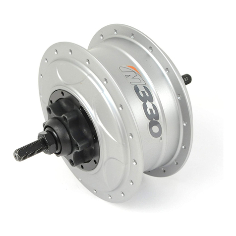
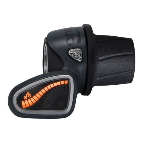
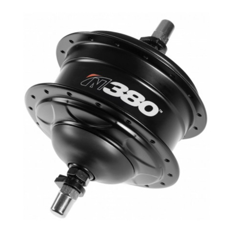
NuVinci enviolo CT User manual

enviolo Assembly Instruction
ASSEMBLY INSTRUCTION
NOVEMBER | VERSION
The
Moving
Standard
for
City
Trekking
Sportive
Cargo
Commercial
bikes.

enviolo Assembly Instruction
Table of
Contents
General Information
Vision
For Your Safety
Designated Use
Safety Notices
Components of Groupsets
enviolo Manual
enviolo AUTOMATiQ
Internal Gear Hub Components
enviolo AUTOMATiQ system
Components
Step by Step Assembly Instruction
Wheel Building
Required Tools
Manual System
Installing the Sprocket
Hub Interface Compatibility
& Orientation
Installing the Manual Hub Interface
Installing the Manual Controller
Installing the Shi Cables
Setting the Shi Cable Length with the enviolo
tool
Installing the Rear Wheel for Manual
Variants
Adjusting Cable Slack
AUTOMATiQ system
Installing the System Sensors
Installing the AUTOMATiQ Hub Interface
Installing the AUTOMATiQ App
Installing the Rear Wheel for AUTOMATiQ
Variants
Installing the AUTOMATiQ controller
Pairing Hub Interface with App and
Controller
AUTOMATiQ Quick Start Guide
Troubleshooting
Assembly Torque Specifications
Replacing Controller Cables
Servicing or Replacing the Freewheel
Removing/Installing Brake Configurations
Wear Parts and Repair Work
Care and Lubrication, Transport and
Storage
Service Tools
enviolo Help Center
Appendix
Required Package Space
Intellectual Property Notice
3
3
4
5
5
6
7
8
9
12
13
14
15
16
16
17
18
19
20
23
24
26
27
27
29
31
35
36
37
38
43
44
46
47
48
49
54
55
56
57
60
71

enviolo Assembly Instruction
The Moving Standard.
We are excited to see that you have decided on the
moving standard with our shiing solution containing the
revolutionary 'CVT' technology. By selecting this internal
gear hub solution, you are ensuring a low maintenance
product life cycle combined with an unrivalled ease of use
controls functionality to give you the best ride performance
available.
These assembly instructions will guide you through the
assembly steps of seing up your bike (or eBike), offers you
tips and tricks in case of required maintenance, and ensures
you know all the features, to get the most out of your ride
experience.
Our stepless technology offers an infinite number of ratios
inside its wide ratio range and will enable you to focus on
the important aspects of a ride, like inner-city traffic or the
scenery, while being able to shi under load in any ride
condition.
Enjoy your ride with enviolo, the moving standard!
Introduction
* available with enviolo manual
** available with enviolo AUTOMATiQ
Stepless
shiing
Effortless shiing,
even under load
Wireless
connection
Mobile app
customisation
Greater gear
ratio range
Comfortable
pedaling at your
desired preset
cadence
No additional
shier
Near
silent

enviolo Assembly Instruction
For Your Safety
Please read the entire assembly instruction and pay special attention to
all safety warnings before use, replacement of components or installation
of enviolo components. Failure to follow the warnings or improper
installation, set up, modification, or maintenance may result in material
damage or in personal injury. Save all safety warnings and instructions for
future reference.

enviolo Assembly Instruction
This notice warns
you about potential
damage to material.
enviolo CA
enviolo CO
enviolo SP
enviolo TR
For Your Safety
Our 5 groupsets are designed specifically towards the rider needs and meet the attributes
of the specific segments as highlighted in the chart below.
Designated Use
asdfasdfdasdf
Product Type of Bicycle Type of Use Allowable Ride Conditions
Minimum Sprocket
Ratio Limit
(Pedal/eBike)
Max Motor Torque
Max
Nominal
Power
Max Gross
Vehicle
Weight
City, Urban,
Commuter
enviolo CT Riding on paved surface with the tires
always on the ground.
1.8/(250W) 2.0 55 Nm 250W 160kg
Trekking,
Urban, Cross,
Commuter
Riding on paved surface or gravel roads or
groomed trails with low-angle grades.
1.8/(250W) 2.0 85 Nm 250W 180kg
Cross,
Sportive,
Cross-Country
Hardtail
Riding on paved surface or gravel roads or forest
paths and smooth technical trails including
small obstacles with low-angle grades and drop
os less than 12" (30cm). It is not intended for
steep or rough terrain. Can be used for commer-
cial application.
1.8/(250W) 2.0 100 Nm 250W 160kg
enviolo SP Speed
Pedelec
Riding on paved surface or gravel roads or
groomed trails with low-angle grades.
1.8/(up to 350W) 2.0 85 Nm 350W 160kg
enviolo SP Speed
Pedelec
Riding on paved surface or gravel roads without
any drop os. Can be used for commercial
application.
1.8/(up to 500W) 2.0 65 Nm 500W 160kg
City, Urban,
Commuter
Riding on paved surface with the tires always
on the ground. Can be used for commercial
applications.
1.8/(250W) 2.0 55 Nm 250W 160kg
Cargo, Delivery,
Transport
Riding on paved surface or gravel roads without
any drop os. Can be used for commercial
application.
1.8/(250W) 2.0 85 Nm 250W 250kg
Safety Notices
The following safety symbols identify the levels of danger and must be observed throughout
this document:
Attention Caution Danger Warning
Do not open our components yourself. All components have to be maintained by trained
service sta.
This notice warns you
about a dangerous
situation which can lead
to minor or slight injury if
not avoided.
This notice warns you
about a dangerous
situation which can lead
to slight injury if not
avoided.
This notice warns you
about a dangerous
situation which can lead
to serious or fatal injury if
not avoided.
Check the proper setup of the system before
every ride to ensure a safe ride.
If you discover any defects, these must be
immediately corrected by your bicycle dealer.
If any parts need to be replaced, make sure
only original parts are used to ensure your
own safety and to maintain the high level
product quality.
We recommend to follow a customer service
inspection, which can identify material
fatigue at an early stage and ensures your
safety.

enviolo Assembly Instruction
Components
of Groupsets
Our high-tech components, designed specifically for their use cases, oer
unrivaled possibilities.

enviolo Assembly Instruction
CO
Components of Groupsets
enviolo Manual
MANUAL
CONTROLLER &
MOUNTING HARD-
WARE
INTERNAL
GEAR HUB
Each manual system is comprised of an internal gear hub with the NuVinci® internal gear hub technology, a front shier, a hub
interface, and the according mounting hardware.
CT TR SPCA
MANUAL HUB
INTERFACE

enviolo Assembly Instruction
Components of Groupsets
enviolo AUTOMATiQ
* The 3-button controller is currently under evaluation.
AUTOMATiQ
SENSORS
The mounting hardware mentioned in the enviolo manual components section (page 7) is also required for
the enviolo AUTOMATiQ systems.
AUTOMATiQ
WIRE HARNESSES
CO
SP CA
CT
INTERNAL
GEAR HUB
Each AUTOMATiQ system is comprised of an internal gear hub with the enviolo internal gear hub technology, a hub interface, a
power cable, two sensor discs and the according mounting hardware.
AUTOMATiQ
INTERFACE,
CONTROLLER &
SHIFTER
TR

enviolo Assembly Instruction
Internal Gear Hub
Components
Axle nuts
No-turn washer
CT/TR/CO/CA hub
Manual Hub Interface
3
4
2
1
1 2 2 1
enviolo CT/TR/CO Internal Gear Hub
For further details on product specifications, please also see technical manual.
1 2 2 1
enviolo CA Internal Gear Hub
67.6
Centerline
49.0
Chainline 4.0
8.5°
41.9
26.0 26.0
135 dropout width
183 axle width
16.0
ISO 6-bolt
disc brake version
3 4
Ø 125
32 and 36 spoke
configurations
available
Ø 52.5
Ø 2.9
spoke hole
3 4
Ø 125
32 and 36 spoke
configurations
available
Ø 52.5
Ø 2.9
spoke hole
68
68

enviolo Assembly Instruction
106
541 8 9 7 32 8 4 1
Manual System
Components
enviolo SP Internal Gear Hub
135mm
2 3
enviolo SP Internal Gear Hub
142mm
For further details on product specifications, please also see technical manual.
1 2
Nut, Acorn
SP hub
1
2
Manual Hub Interface
Lock washer, M10
3
4
Adapter, Torque Reaction
5
Retaining ring
Axle plate, 135 mm
6
7
Sha, threaded adapter
Bolt, countersunk, Torx,
M4 x 0.7 x 8
8
9
Washer, spacer, 13 x 19 x 0.5
10
SP hub
Manual Hub Interface
1
2
Adapter, lock nut, OD20 or
OD22, 12 x 142 / 12 x 148
compatible
Axle plate, 142/148 mm
3
4
Retaining ring
5
Spacer, LH
Spacer, RH
6
7
Brake caliper mount IS to PM
Brake caliper mount PM to PM
8A
8B
Bolt, countersunk, Torx, M4 x 0.7 x 8
9
A
8A
5
11 6 9 4 21 3 7 1112
10
B
8B
Washer, spacer, 13 x 19 x 0.5
10
Socket head cap screw, M6
11
Adapter, Torque Reaction
12
Syntace
DT Swiss, Maxle, E-Thru
A
B
A
B
Ø 125
32 and 36 spoke
configurations
available
Ø 52.5
Ø 2.9
spoke hole
Ø 125
32 and 36 spoke
configurations
available
Ø 52.5
Ø 2.9
spoke hole

enviolo Assembly Instruction
Manual System
Components
enviolo SP Internal Gear Hub
148mm
For further details on product specifications, please also see technical manual.
3 4
A
8A
5
411 6 9 4 21 3 7 1112
10
B
8B
Syntace
DT Swiss, Maxle, E-Thru
A
B
SP hub
Manual Hub Interface
1
2
Adapter, lock nut, OD20 or
OD22, 12 x 142 / 12 x 148
compatible
Axle plate, 142/148 mm
3
4
Retaining ring
5
Spacer,LH
Screw, button head, M5 x 0.8 x
16L, alloy
6
14
Brake caliper mount IS to PM
Brake caliper mount PM to PM
8A
8B
Bolt, countersunk, Torx, M4 x 0.7 x 8
9
Washer, spacer, 13 x 19 x 0.5
10
Socket head cap screw, M6
11
Adapter, Torque Reaction
12
Spacer,RH
7Spacer,discbrake,12x148
13
1314
A
B
Ø 125
32 and 36 spoke
configurations
available
Ø 52.5
Ø 2.9
spoke hole

enviolo Assembly Instruction
J16/Hirose
J15/Hirose
Hirose connector: WIRE-AT3-400-OE
WIRE-AT3-600-OE
Wire diameter = 3.7 mm
0,400 m 0,72 m
enviolo CT: AHI-AUT-CT-OE
enviolo CO: AHI-AUT-CO-OE
enviolo TR: AHI-AUT-TR-OE
enviolo CA: AHI-AUT-CA-OE
enviolo SP: AHI-AUT-SP-OE
Available from drive
system manufacturer.
J15 J16
This diagram provides you an overview of the system connections.
I-Harness
AUTOMATiQ Wire Harness
I-Harness
J6 (connector side) / Mini F
enviolo AUTOMATiQ is a CAN Bus / BLE system
J6
J5 (AHI side) / Mini F
Wire Harness
NOTE: Pin-Numbering on AHI-side is dierent from Pin-
Numbering on Cable-side
* This connector is only required if the counterplug is not provided by the drive system
manufacturer. Please contact the drive system manufacturer for further information. For Yamaha
we oer an alternative cable. Please contact the sales team for further information.
Stepless
shiing
Effortless shiing,
even under load
Wireless
connection
Mobile app
customisation
Greater gear
ratio range
Comfortable
pedaling at your
desired preset
cadence
No additional
shier
Near
silent
J5
-------OR -------
WIRE-AT3-DS-OE
GND
V_BAT
CAN LOW
CAN HIGH
1
2
3
4
2
3
4
1
Cable Pin Color
Yellow
Blue
Red
Black
V_BAT
GND
CAN_L
CAN_H
Function
HI Pin

enviolo Assembly Instruction
Step by step
assembly instruction
Enjoy the ride!

enviolo Assembly Instruction
Wheel Building
• The anti-shi retainer provides 135mm spacing, and should remain
on the CVP during lacing and wheelbuilding.
- The maximum spoke diameter is #13/2.34mm
- The minimum spoke diameter is #14/2.00mm
• Suggested lacing is a -cross pattern for 26 inch and 700c wheels.
- Use a 3-cross pattern only if the rim allows the nipples to be
eectively in-line with the spokes.
• For 24 inch or smaller wheels a 1-cross pattern is suggested. A
3-cross pattern is not recommended since the hub size makes the
angle between spoke and flange unfavourable.
• Radial lacing is not recommended.
• In order to have a symetric wheel assembly on the 148mm version,
please insert the wheel dishing spacer between the hub and the non
drive side bolt [A].
Installation and repairs must be made by a qualified bicycle
mechanic.
This section assumes a level of knowledge and skill
consistent with that of an experienced bicycle assembler
or bicycle mechanic.
Our internal gear hubs can be laced in 20" to 29" wheels. We oer both 32
and 36 hole variants. When selecting spokes and rims, please ensure you
select durable spokes and rims suitable for the use with an internal gear hub
or rear motor. They should be 13 or 14 gauge.
A
All components on the side of brake disc are not assembled.
A

enviolo Assembly Instruction
Required Tools
The following tools are required:
Tool Tool
Flat tip screwdriver
Cutting pliers
2mm Allen wrench
2.5mm Allen wrench
3mm Allen wrench
15mm wrench or long socket
17mm wrench or long socket

enviolo Assembly Instruction
Manual system:
INSTALLING THE SPROCKET
Installing the
Sprocket
1. [A] Remove the anti-shi retainer (A) by pulling
firmly away from the enviolo internal gear hub.
2. [B] Install a standard 9-spline 3/32 inch (2.3mm)
sprocket (B) with the flat side facing the hub ,
followed by the supplied sprocket spacer (C, if
required), and secure with the sprocket snap ring.
3. The sprocket spacer is intended for sprockets that
are 3/32 inch (2.3mm) thick at the inner diameter. If
the inner diameter is 0.17-0.18 inch (4.3-4.5mm)
thick, like belt cogs, the spacer should not be used.
4. If you are using the enviolo CO hub you can also
use a 3mm offset sprocket single speed chains
(1/8").
The offset is facing inward, moving the chain closer
to the internal gear hub.
All other enviolo hubs should only use 3/32 inch
sprockets that are flat on at least one side. If you
use incompatible chains this can lead to
interference with the hub interface and damage to
hub components and may result in dangerous ride
conditions for the rider.
5. The enviolo hubs are compatible with 16 to 28
tooth sprockets.
6. If a hub interface is not installed immediately
following the sprocket, replace the anti-shi
retainer (A).
[C] Note: If you are using the 16T sprocket, please make
sure to use 1mm spacers on each side of the sprocket for
proper fit and clearance.
B
C
A
A
B
C

enviolo Assembly Instruction
Hub Interface
Compatibility
& Orientation
• [C] Use the uninstalled enviolo hub
interface to determine the desired
orientation. Typical orientation is
forward, parallel to the chain stay or
seat stay cable routing.
Move the enviolo hub interface along the
dropout to ensure clearance at dierent
axle positions. For the variant SP the
orientation is not imporant.
• [D] With the interface oriented
correctly inside the right dropout, the
installation angle is the indicated
angle of the dropout (20 degrees in this
example).
• [D] Use the markings on the hub
interface to determine your approximate
installation angle.
• [E] There are 5 dierent hub interfaces,
which require dierent assembly steps
for the standard and the one-turn
versions as described on the following
pages.
C
Manual system:
INSTALLING THE MANUAL HUB INTERFACE
D
E

enviolo Assembly Instruction
Installing the Manual Hub
Interface
• [F] Remove the anti-shi retainer, if installed and ensure that
markings between the splined nut and the shi driver are aligned.
• [H] Prior to installation, set the hub interface to the full overdrive
position.
• Suspend the hub interface over the right hand axle, and align the axle
flats with the installation angle.
• Alternatively, a no-turn washer can be installed over the interface to
align the installation angle.
• When the installation angle is aligned, ensure the hub interface is
set to full overdrive and seat the hub interface fully onto the shi driver
andt he spline nut until it is flush with the spline nut, as shown.
• Thread the r.h. nut , serrations facing outward, onto the axle and
tighten to 10-15 Nm (7-11 -lbs). Install the rear wheel.
• [I] For the variant enviolo SP 135 mm:
Thread the adapter shas into the hub and tighten to 10-15Nm.
• [J] For the variants enviolo SP 142/148 mm:
Place the spacer on the hub and thread the LNUT onto the axle and
tighten to 5-6 Nm
Manual system:
INSTALLING THE MANUAL HUB INTERFACE
F
G
H
IJ

enviolo Assembly Instruction
I
Manual system:
INSTALLING THE MANUAL CONTROLLER
J
K
• Install right brake lever according to the
manufacturer’s instruction.
• [I] Slide the controller onto the handlebar.
• [J] Install the right hand grip onto the
handlebar according to the
manufacturer’s instructions.
• [K] Position the controller such that the
display is visible to the rider and the
cable will be unobstructed.
• Barrel adjusters can be used for
optimization of cable slack.
• Tighten the clamp bolt to 2.0-2.5 Nm (18-
22 in-lbs).
Make sure that the
controller and the
brake lever function
properly and are
unobstructed (re-adjust
if necessary). E.g.: the
controller not being too
tightly mounted with the
grip.
Never ride without
the handlebar grips.
The turning grip of the
controller could become
loose. This can result
in a severe injury.

enviolo Assembly Instruction
L
Manual system:
INSTALLING THE SHIFT CABLE HOUSING
• Route cable housing as shown from the
controller to the manual hub interface.
• Measure, cut and install the appropriate
length cable housing for the bicycle.
• Full-length housing is recommended for
both shi cables.
• Make sure that the cable housing lengths
are suicient to allow an extreme turning
angle. Also consider the influence of
adjustable handlebars and stems on the
cable housing lengths.
• Secure cable housing to the frame. The
cable housing must remain moveable
for axle adjustment.
• Avoid tight bends when installing the
shi cable housing.
• Leave at least 150mm of housing
unsupported at the manual hub
interface to ease installation and
removal of the shi cable hardware.
• With the housing length correct, install
end caps at both ends of each
housing.
1
2
underdrive
overderdrive
M
The underdrive cable end
should be colored green or
black. The overdrive cable
end will be uncolored.
Ensure the housing
diameter is correct. Too
big or too small diameters
can have a negative
eect on shi forces and
performance.
This manual suits for next models
4
Table of contents
Other NuVinci Bicycle Accessories manuals
Popular Bicycle Accessories manuals by other brands

Continental Refrigerator
Continental Refrigerator Ergon Series Original instructions

Pioneer
Pioneer SGY-PM910HR user manual

Rose electronics
Rose electronics RACE ATTACK RA-1 owner's manual

Flexcom
Flexcom FB222 Installation and operating instructions

Marzocchi
Marzocchi 320 LCR CARBON manual

TerraTrike
TerraTrike Pedal Platform installation guide