10
EN
TECHNICAL OWNER MANUAL
NFINITY ASSEMBLY OF COMPONENTS
A
B
C
D
• See section 5.1 (for chainline and beltline
specifications)
• The NuVinci Optimized CVPs are
compatible with 16 to 28 tooth sprockets.
See section 5.1 for sprocket ratio
requirements and approved gearing
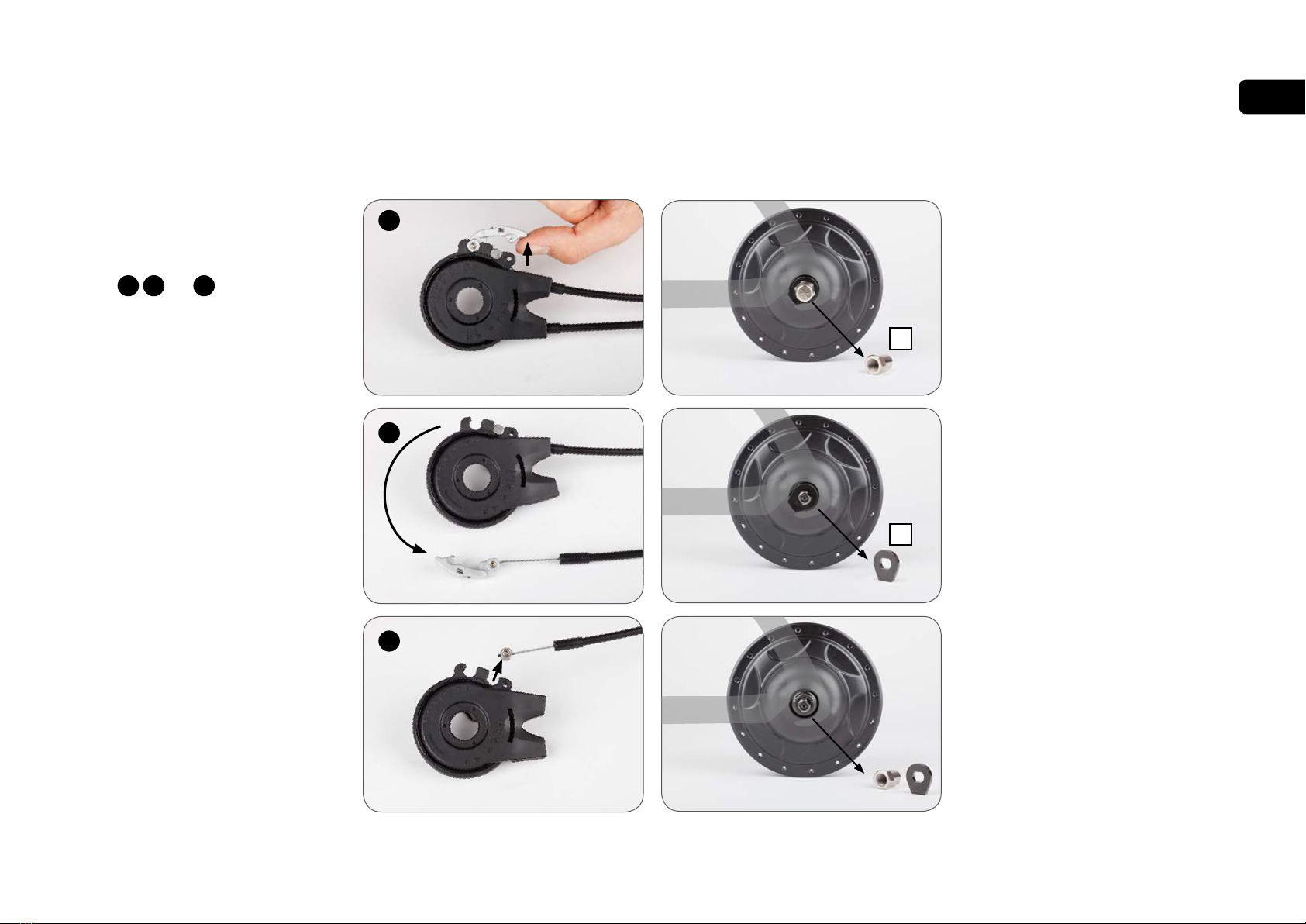
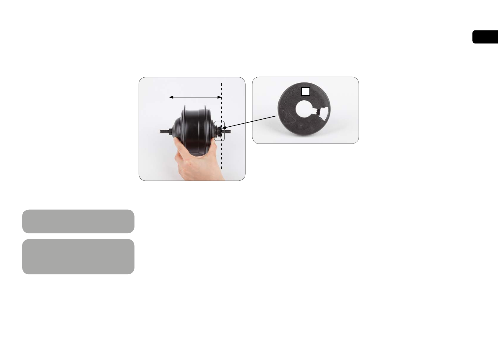
3. If a Nfinity Hub Interface is not installed
immediately following the sprocket, replace
the anti-shift retainer (A)
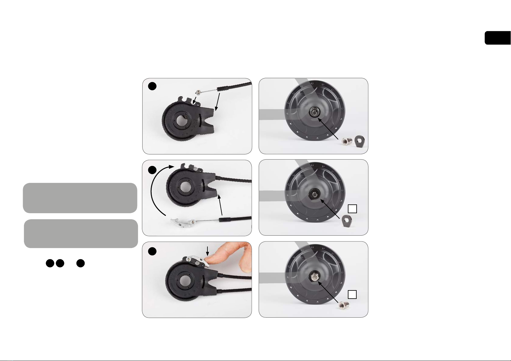
3.2 Installing the Sprocket
1. Remove the anti-shift retainer (A) by pulling
firmly away from the NuVinci CVP
2. Install a standard 9-spline 3/32 inch
(2.3mm) sprocket (B) with the flat side
facing the CVP, followed by the supplied
sprocket spacer (C, if required), and secure
with the sprocket snap ring (D).
• The sprocket spacer is intended for
sprockets that are 3/32 inch (2.3mm) thick
at the inner diameter. If the inner diameter
is 0.17-0.18 inch (4.3-4.5mm) thick, the
spacer should not be used.
Use of incompatible chains can
result in interference with the Nfinity
Hub Interface and damage to CVP
components and may result in a dangerous
condition for the rider.
NuVinci Optimized CVPs are
incompatible with 1/8 inch
(3.18mm) single-speed chains and
sprockets that are flat on at least one side.
Use 3/32 inch (2.3mm) chains and sprockets
only.
If the sprocket is asymmetric, incorrect
installation can result in interference
with the Nfinity Hub Interface and
damage to CVP components and may result
in a dangerous condition for the rider.
!
!
!
Nfinity 330 systems are compatible
with mid-motor eBike systems rated
at 250W or less. See section 5.2 for
approved gearing tables.
Nfinity 380 systems are compatible with mid-
motor eBike systems rated at 350W or less.
See section 5.2 for approved gearing tables.
!